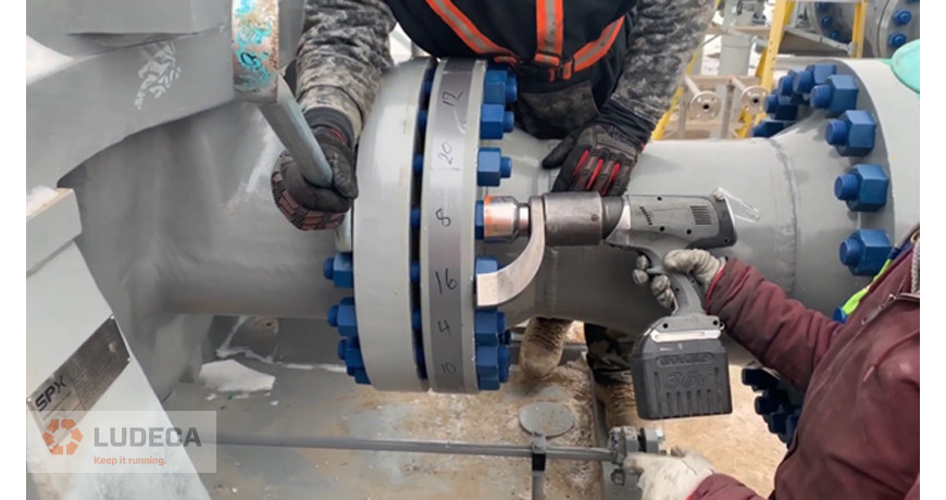
“Reliable machinery installation” – it sounds like an obvious thing, don’t you agree? But where does reliability actually start?
We all know that “the thing” starts with the design. The design stage decides what is going to be installed. Which equipment, and where. But there is no decision on Who is going to perform the installation, and How it is going to be installed. Most of the time those two departments are not cooperating, especially if they don’t belong to the same organization. The installation teams must be involved in the design because they will provide their feedback for reliable machinery installation. They know exactly how things work out there and how they need to be done.
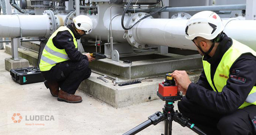
Every day I see on social media tons of information regarding reliability maintenance, condition monitoring, sensors, cameras, and all possible problem-solving technologies. All those technologies provide the necessary information from our assets. Things we need to know in order to evaluate the condition of our assets. But what about the most crucial step? Machinery installation, anyone? I have been assembling and building skids and gas compression systems for the gas and petrochemical industry for many years. My experience has shown me that “flatness and levelness” is one of the most critical issues when it comes to the assembly of rotating machinery.
Designed for flatness and levelness
All machinery is designed to work on a flat and leveled surface. Every manufacturer of pumps, compressors, blowers, electrical motors, and gearboxes assumes that their equipment is going to be installed correctly, meaning on a flat and leveled surface. And they also provide their tolerances for this. There are standards for the installation, too. ANSI standards recommend foot flatness less than 0.4µ/mm [5 mils/ft]. And coplanarity is less than 50µm/mm [2 mils] between the machines and their drives for machines up to 400kW or 500 HP. ISO standard for centrifugal pumps for petroleum, petrochemical, and natural gas industries (ISO 13709:2009) says clearly that “Corresponding surfaces shall be in the same plane within 150µm/m”. That is 0,15mm per meter. Levelness has the tolerances less than 0,8 µm/mm [10 mils/ft].
Flatness and levelness affect everything
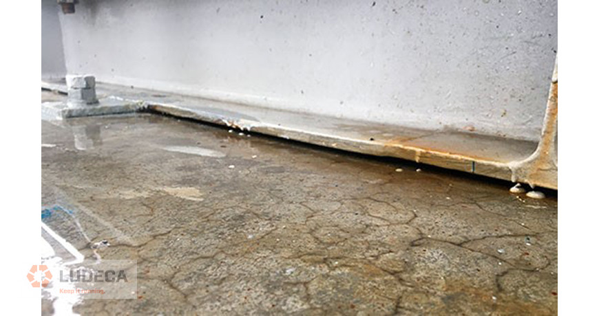
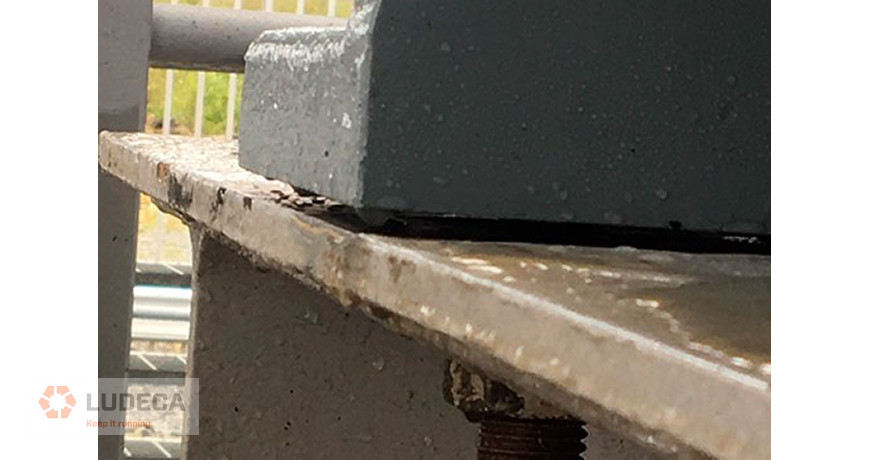
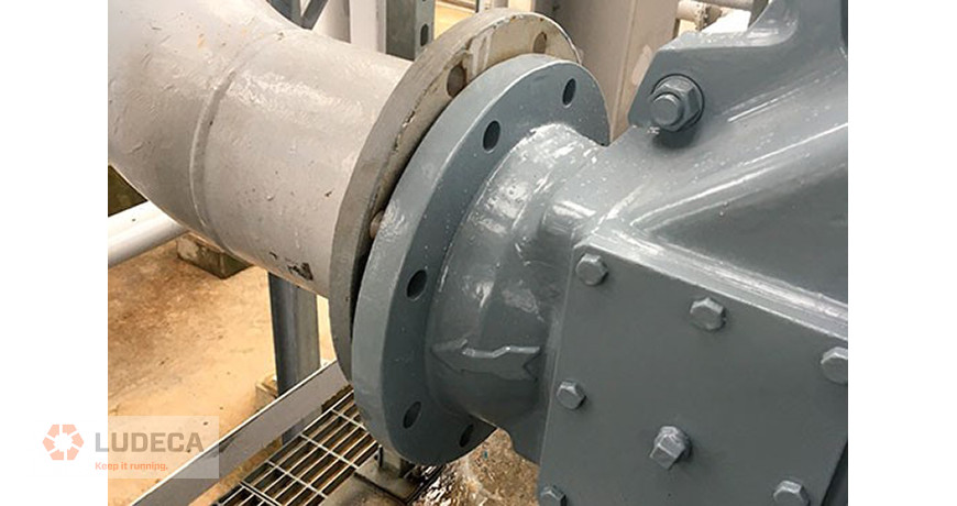
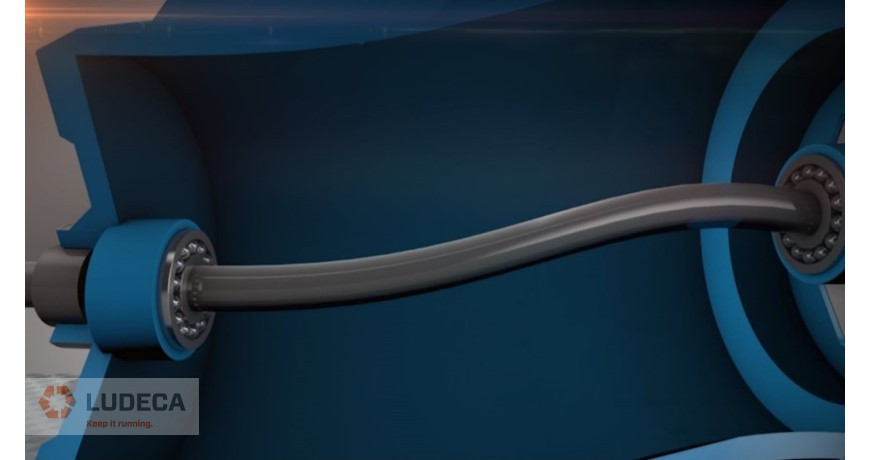
Checking the flatness of the foundation is essential. The foundation is the cornerstone for every single installation, irrespective of type. Mounting pads, soleplates, frames, and tables. Everything you put on top of them is going to be affected. When the flatness is out of tolerance all rotating equipment is affected. Soft foot, misalignment, machine casing stress, pipe flange misalignment, and many other causes. But I want to mention specifically one, and that is a strain in the bearings. The bearing is designed to rotate using the oil film lubrication. According to Swedish bearing manufacturer SKF, a free-running bearing with the proper lubrication will rotate to infinity. When the bearing is squeezed, the lubrication film is forced out and contact metal-to-metal appears. Excess heat is generated, and your bearing is running into failure. That simple. All other failures will be linked to it. And it often started with a flatness issue. Levelness is another factor affecting heavily the equipment. Vertically installed bearings carry on horizontal loads and if you change their gravity point, the lubrication will move out of their raceway. If you don’t have proper lubrication film, there will be metal-to-metal contact. If you have splash lubrication in your machine, and you have unlevelled installation, you will move the oil away from the oil slinger. That will be the end of the story.
Why would you install your asset on bases which are not checked for proper flatness and levelness and face all the problems related to it? After reading this you can at least not claim “I didn’t know it was important…”
Thank you Roman Megela with Easy-Laser for sharing this informative article with us!
by Ana Maria Delgado, CRL
A topic I like to highlight and elaborate on during a training session is alignment tolerances. In my experience, I have found that most people involved in alignment don’t give tolerances much thought. Alignment tolerances are useful in that they give the technician doing the alignment a stopping point. But tolerances can vary widely: From coupling manufacturers whose tolerances are as wide as the Grand Canyon, to company X’s engineer who years ago decreed all alignment should be under 2 mils at the feet, the question is always asked: Which alignment tolerances should we use?
Today, most laser alignment tools have some sort of tolerance table built-in that is adjusted to the speed of the rotating equipment being aligned, along with some sort of indication that the value has been reached. Also, in recent years the American National Standards Institute (ANSI) developed (with the help of “alignment gurus” in the industry), a set of alignment tolerances for rotating equipment. In the case of our Easy-Laser XT systems, both of these options are built-in. The user can choose to use the default tolerances or a national standard for alignment tolerances. Both are close in their values. Below is an example of the ANSI standard for common RPMs, offering Minimal, Standard, and Precision tolerance values, for the parameters they named: Offset and Angularity Method.
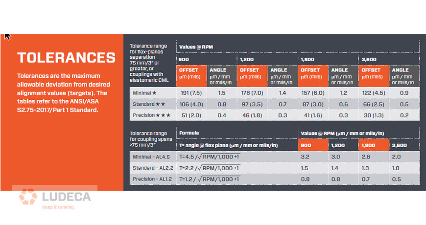
Let’s assume that the machine being aligned runs at 1800 RPM. The precision offset tolerance, in this case, is 1.6 mils (0.0016 inches). In the case of the Easy-Laser XT systems, the tolerance indicator is color-coded to each of the three options (Minimal in orange, Standard in yellow, and Precision in green.)
The point I like to emphasize in my training is, what happens when the final measurement shows the alignment to be at 1.8 mils of offset? The tool will not show green for the offset tolerance. It will instead show yellow because it is outside of the 1.6 mil threshold. But let’s think about what’s actually happening. The alignment is essentially 0.2 mils (0.0002 inches) away from giving a green indicator. So, the question we need to pose is:
Is it worth the time and resources to loosen up the bolts and make adjustments at the machine feet to correct 0.2 mils of offset at the coupling center to achieve Precision alignment?
The answer depends on how difficult it has been to achieve the 1.8 mils. It also depends on the condition of the baseplates, residual soft foot, length ratios of the machine, and what other tasks are planned for the day. If the 1.8 was achieved after the first move, and soft foot was fixed relatively easily, then making another move to fall within the precision tolerance may not be that difficult. On the other hand, we need to consider the fact that in the attempt to improve this alignment condition, it could get worse. Therefore, if the technician has been dealing with a baseplate that pulls the machine upon torquing the bolts, has a residual soft foot condition, or is simply needed in another part of the plant, it may not be worth it to make that small of an adjustment.
This is the reason why I always recommend reviewing the allowable tolerances for the machine being aligned prior to starting the alignment. This way we shift our focus from striving to achieve zeros, to reaching a tolerance value that has been studied and proven to be good enough. In the case above, knowing that the value needed to achieve precision alignment is 1.6 mils, will aid in making the decision on whether to make that final move or not, because focusing on tolerance indicators can lead to time wasted in making machine corrections when those resources could be used on more important tasks.
by Adam Stredel CRL
We previously went over our glossary of alignment terms with, “What is Alignment? Check out our Glossary of Alignment Terminology from A-H!” and later with Alignment Terminology from I-R.
In the world of alignment, there is a multitude of technical terms. We provide definitions for some of these terms that you might hear from an engineer or technician as well as read in reports and might need further clarification. We welcome you to check out our glossary of terms S-Z relating to alignment, and hope you find it valuable!
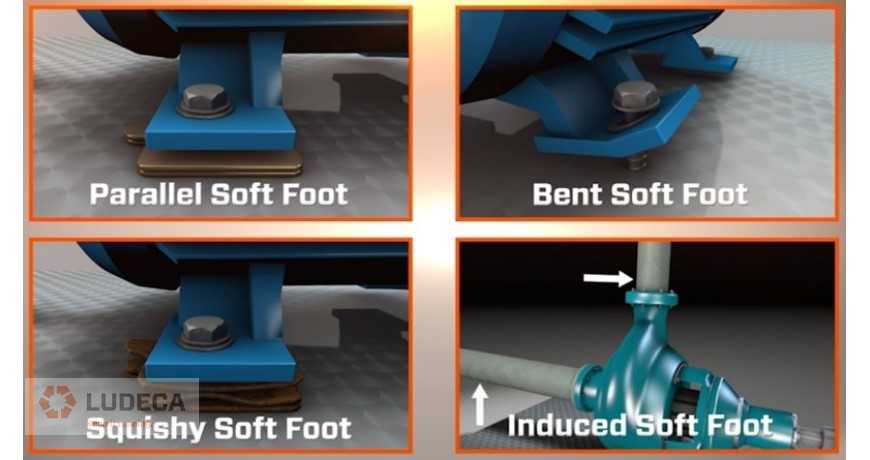
SOFT FOOT – A term used to describe any condition where tightening or loosening the bolt(s) of a single foot distorts the machine frame. Must be corrected prior to final alignment.
SPACERS – A generic term for any coupling characterized by two flex planes separated by a connecting shaft without bearings or other supports between the flex points.
SQUISHY FOOT – A type of soft foot characterized by material (could be shims, paint, rust, grease, oil, dirt, etc.) acting like a spring between the underside of the machine foot and the baseplate contact area.
STAT – A short form of “stationary machine”. The stationary machine’s centerline is used as the reference line to measure the misalignment of MTBM (Machine To Be Moved).
STEP SHIM – Use of several shims to fill the wedge-shaped gap of a bent foot. Each shim is inserted to a different depth so that a stair-step-shaped support is built to better support the entire foot. All of the steps together are called a step shim.
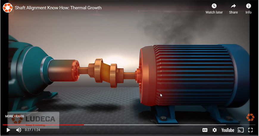
THERMAL GROWTH – Movement of shaft centerlines associated with (or due to) a change in machinery temperature between the static and operating condition.
TOLERANCE – The maximum permissible deviation from a specified alignment position, defining the limits of offset and angularity.
by Ana Maria Delgado, CRL
Precision Maintenance can be used as a process improvement strategy. A strategy that will pay dividends. This process is easy to implement. In fact, you do most of the work already. The beauty of it all is that there is not a lot of cost involved and if you are smart, you can implement the process on one machine at a time.
Precision maintenance is not new, it has been in our company name BENCHMARK PDM for many years. We chose the word BENCHMARK because it means a standard by which something can be measured from. The acronym PDM stands for precision-driven maintenance. So, our goal has been and still is to set the standard for precision maintenance.
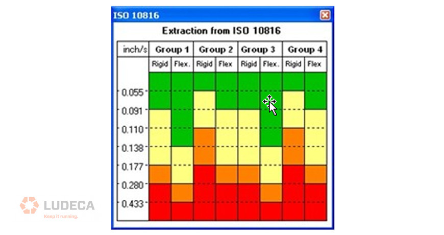
In simplistic terms, Precision Maintenance means working to a recognized standard tolerance or specification. Just doing that will improve your work processes, and the payoff is a much improved and reliable machine (asset). It is important to note that when I say recognized, it means the standard is approved by an organization such as the Canadian Standards Association (CSA), the International Standards Association (ISO), or the American National Standards Institute (ANSI). There are many used in the industry, a common one is the ISO 10816 vibration standard tolerance chart (see image below).
Are there exceptions to using a recognized standard? Absolutely. There is the American Petroleum Institute API686 and while only a guideline and not a standard, this document was the go-to bible for anyone doing pump installations and still is.
When implementing Precision Maintenance there are five things that you should already have or need to have to be successful.
1. Work Procedures
Work procedures are written documents that follow the work process. You have them as part of your Preventive maintenance program. But do you have them for a pump overhaul? The procedure should include the standard tolerances and specifications you would need doing the work. What this would give you is consistency. If you do not have written procedures or old outdated ones, the best people to write them are the tradesmen as they know the work process the best. Better still, do it as a team-building exercise as it creates buy-in. However, they must be clear, with no ambiguity, all must understand and be on the same page.
2. Measuring Tools
Precision Maintenance requires exact measurement. Obviously, you need instruments that can achieve this. The actual recommendation is to use instruments that can measure under the tolerance you require. The tighter the tolerance the better the result but you cannot have a tolerance that you cannot measure. This means you need the right tools for the job. Always try to use digital so that the measured value or result is saved electronically. It is a known fact that when using instruments such as theodolites, dial gauges, or levels, for example, the greatest error occurs during the transfer of the seen value. My one piece of advice is do not buy junk. You need something that the team will use. Get them involved in choosing the tools required.
3. Data processing system
This is so important because it gives you an organized structure. You probably have a PM program, which of course is a must, that is controlled by a CMMS/EAM system. In it, you will have planned work orders, backlog orders, PM schedules, CBM tasks, etc.
Depending on the capabilities of your CMMS/EAM you should have an individual file for all the plant’s assets. Each one should be a benchmark record of the machine’s normal operating condition. For example, the normal operating temperature should be known, and where you would take those measurements to verify this. Simple enough to do but so helpful for the PM tech. There should also be an asset history file.
And this is where we often see the breakdown in the system. There may be a file but what is missing from many is the asset/machines installation report or a coming into service report. This is the information that controls the reliability of this machine. Imagine if you had to do a breakdown analysis after a failure and did not have this information. You would be relying on guesswork or maybe wrong information.
A Precision Maintenance program guarantees that you have this file because a precision machine installation has mechanical measured items such as these below.
- Base flatness and level
- Shaft runout
- Coupling runout
- Pipe and conduit strain
- Soft foot
- Offline To Running (OLTR) machinery movement
- Shaft centerline to shaft centerline (alignment)
All of these items and the recognized standard tolerances/specs can be found in ANSI/ASA S2.75-2017/Part 1. An installation report and a commissioning report guarantee the machine has a good starting point when starting service. And throughout its life, there will be added work to this report such as “As Found” and “As Left” alignments or a base flatness change as things do move over time.
4. The right skill sets for the work
I had a conversation with a maintenance shop foreman who suggested that not everyone in the shop had the same-sized toolbox and that he would pick and choose who to put on what job. What he meant was that not everyone has the same skill set. For example, I know a company that bought an expensive and not-so-user-friendly laser alignment system. The problem is that not all the shop guys can use it. It may be taken to the job site but unfortunately not used correctly or not used at all. This is one of the reasons we are developing training videos to help support some tradesmen who struggle with new technology. They can take their time and review it as often as they like especially before going out to do an alignment job. With Precision Maintenance all should be proficient in taking and recording measurements. So, you may want to invest in training.
5. The right team culture
I first heard the term Precision Maintenance from Ralph Buscarello of Update international who is the gentleman that taught me shaft alignment using dial indicators almost 40 years ago. I have heard others promoting this as the next big thing. But the reality is that it has been with us for a long time. Some companies, not a lot, do it, others do it but not as successful.
If you are in maintenance, whether in management or skilled trades, embarking on such a program as this is challenging. It is a very worthwhile program, but it is a big commitment to do it and stay with it. The overall benefits are large in the form of machine/asset reliability. A side benefit is that you have to do this together as a group, dare I even say team, which does put some people off. However, there are different cultures that produce different teams. You may want to hug every morning before starting work, but others won’t. In today’s industrial environment it should be evident to all that we have to work together in order to compete. So, my advice is that you sit down collectively and ask some tough questions such as can we do this and what do we need?
In today’s world of Covid, we use scientific knowledge to help us make choices or decisions about our health. That is not unlike what you do with your Condition Based maintenance program where decisions are based on the measurement/data that is taken. It is the same with this program. It is data-driven. Quantifiable, reproducible measurements are taken, analyzed, and compared to a standard. Decisions and or actions are taken and the whole process is documented. For well over ten years our training has been called MAAD which is an acronym for Measure, Analyze, Act and Document. I would suggest that you do something along the same lines as this if you want to improve your maintenance process. And quite simply do the job right. You are doing the work already.
Thank you to Benchmark PDM for sharing this blog with us!
What Impact Does Precision Maintenance Have On Your Equipment?
by Ana Maria Delgado, CRL
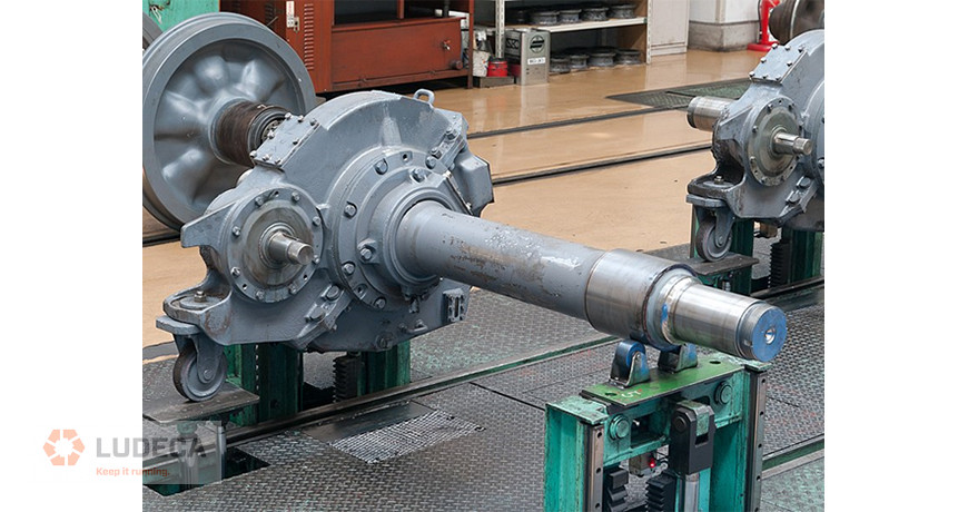
If your machine’s gearbox, pump and motor shafts are not in alignment, the cost of failures and repairs can be drastic. Misalignment of this nature will significantly reduce its performance and mean time between repairs, as well as the functional longevity of the gearbox, motor, and the machines as a whole!
It’s important to be proactive and ensure the gearbox and motor pump shafts are in alignment and working order. This will not only prevent the above but holds notable benefits too. Any downtime will be eliminated thanks to increased productivity and availability of the machine, the bearings preserved, the seals will be protected for longer to prevent leakages and replacements, the risk of overheating and secondary damage will be removed, lubricants will not leak, and serious breakdowns will be avoided.
But, how do you know when your gearbox and motor shafts are not in alignment? As a leading expert in machinery installation, we’ve got some helpful signs you can look out for.
-
Physical Signs
As mentioned above, it’s vital to be proactive and make sure your gearbox, pump and motor shafts are in alignment before it wreaks havoc on your machines. Inspect and take a good look at your machines to assess the health of the interconnected components. If the damage is already done, you will notice:
- Damaged seals and couplings
- Deteriorating bearings
- Vibrations in the gearbox
- Damaged gears
- Higher machine temperatures
-
Seal Leakage
This tends to be the first sign that your gearbox, pump and motor shafts are not in alignment. More specifically, it indicates a significant angular misalignment! If your machine is a pump and has seals, the likelihood of angular misalignment, in this case, is almost guaranteed.
Essentially, the seal has been deflected by the misaligned shafts, causing them to deteriorate and allow leakages to appear. This can greatly reduce the efficiency of lubricant consumption and must be attended to immediately.
-
Damaged Bearings
Unfortunately, this is a silent sign that tends to only be identifiable sometime after misalignment has begun. The bearings that support the shaft will have undergone extreme loads that cause pitting in the races or balls. Pitting of the gears themselves is also possible, as this excessive load will put pressure between the gear teeth. In severe cases, this can actually cause the cage to fail! Once your bearings are damaged, you may also notice drastically increased vibration.
If you notice any one of these signs, you should be ready to shut down the machine for maintenance and alignment.
Thank you to Benchmark PDM for sharing this blog with us!
by Ana Maria Delgado, CRL
We previously went over our glossary of alignment terms with, “What is Alignment? Check out our Glossary of Alignment Terminology from A-H!” In this blog, we continue the alignment alphabet from I-R.
In the world of alignment, there is a multitude of technical terms. We provide definitions for some of these terms that you might hear from an engineer or technician as well as read in reports and might need further clarification. We welcome you to check out our glossary of terms I-R relating to alignment, and hope you find it valuable!
INDUCED SOFT FOOT – A type of soft foot that is caused by external forces (coupling strain, pipe strain, etc.) acting on a machine independent of the foot-to-baseplate connection.
JACKSCREW OR JACK BOLT – A bolt or screw attached to the base or foundation is used to move or position the MTBM (Machine To Be Moved) horizontally.
JACKSHAFT – A long shaft used as a spacer between 2 machines. (Generally used to describe connecting shafts more than a few feet in length.)
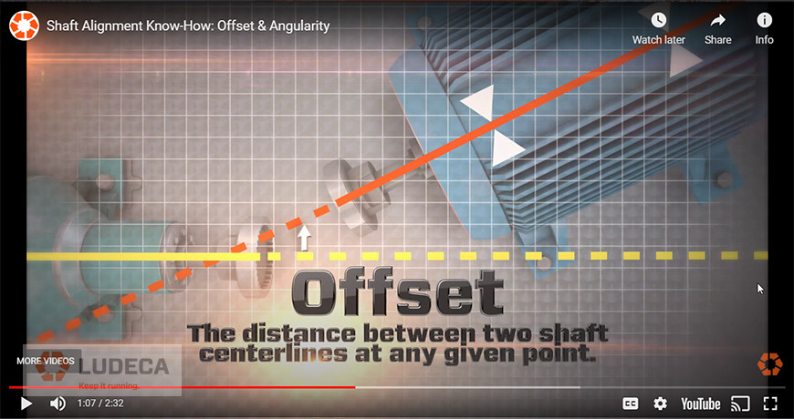
OFFSET – Distance between rotational centerlines at any given normal plane. For short coupling (short flex) is usually displayed at the coupling center.
PARALLEL AIR GAP – A type of soft foot characterized by parallel air space between the underside of the foot and the baseplate contact area.
REPEATABILITY – The consistency (or variation) of readings and results between consecutive sets of measurements.
RESOLUTION – The smallest change or amount that a measurement system can detect.
Stay tuned for the final installment of alignment glossary terms!
by Diana Pereda
If we want to get into precision maintenance, we need to be aware of the differences between shaft alignment tolerances and coupling tolerances.
I just recently read an article from an online Reliability Maintenance website. It’s from a well-known organization that sells training for Reliability Centered Maintenance and Condition Based Maintenance programs. The title read:
“The precision maintenance revolution brings world-class reliability performance to your machinery and mechanical plants and equipment.”
Although the sentence isn’t very well written, it’s a good article that explains what precision maintenance is.
Is there a precision maintenance revolution? Or is it something that is just driven by marketing? Precision maintenance isn’t new, it’s been in our company name for many years. The PDM in BENCHMARK PDM stands for precision-driven maintenance. Apparently, the term precision maintenance was first used by some actual rocket scientists who worked for NASA in the sixties. I first heard the term from Ralph Buscarello of Update international who is the gentleman that taught me shaft alignment using dial indicators almost 40 years ago. So, what is precision maintenance? If you look at precision in the dictionary, we are told it is:
- The state or quality of being precise; exactness.
- The ability of a measurement to be consistently reproduced.
The two keywords for me is exactness and reproduced. As we know, a carpenter measures twice before cutting once. If the measurements are not the same (reproduced), he does not cut until he answers the question why?
Exactness makes statements such as “that’s close enough” redundant because we do not want “close”, we want it to be within tolerance.
That to me is how I define precision maintenance. It’s simply working to a tolerance. The reason we must work to an accepted tolerance range and not to an “exactness” is because in an environment such as rotating machinery, machines and mechanical parts are constantly subjugated to constant forces in which an exact measurement can’t be fulfilled. The problem is some people get confused by some of the tolerances that are out there in our maintenance world – especially when it comes to shaft alignment and the major mechanical parts involved.
Request your complimentary copy of our Shaft Alignment Fundamentals Wall Chart which highlights the ANSI/ASA Shaft Alignment Tolerances as well as information and guidelines for the implementation of good shaft alignment of rotating machinery, best practices, soft foot, tolerances, thermal growth, and much more!
Thank you John Lambert with Benchmark PDM for sharing this educational article with us! Click here to continue reading: “Are You Using Coupling Tolerances to Align Your Machines? You’re Doing It Wrong.”
by Diana Pereda
I recently spoke to a reliability engineer who was rolling out our alignment and vibration equipment to fifteen plants across the U.S. He involved us early on in the process. His company didn’t just set aside budget money for the equipment purchase, but also enough to properly train their field service personnel in how to properly use and benefit from the new technologies. We addressed not only the use of the alignment tools but also proper equipment installation, lubrication, soft foot, pipe strain, thermal growth, etc.
One of the key topics of discussion was alignment tolerances. Since this customer has high-speed ammonia compressors, this was a key concern for good alignment and they, therefore, adopted the new ANSI/ASA Standards alignment tolerances as their corporate standard. Since these tolerances are built into our laser alignment system, it was not only easy for the user to determine if the measured alignment met their established corporate alignment standards, but also for management to review the work to ensure it was correctly completed. This oversight is easily accomplished via signed PDF documentation that allows storage of the “as found” and “as left” alignment results with the work order, and also allows for easy report generation in the field for review.
I was told that their vibration analysis program still identified equipment that was out of the established alignment tolerances. How could this happen? It turned out that contractors were performing work without being held to the same standards as plant personnel, including meeting the prescribed alignment tolerances or using specific alignment equipment to perform the work. In addition, the contractor was not required to provide a copy of the results for review and digital storage.
How could this happen? Unfortunately, it is not so uncommon. Many facilities or corporations do not require that maintenance activities be performed to standards or with the equipment they can trust for the results. Additionally, they do not clearly write job plans that are issued to internal maintenance employees or contractors that specify how the acceptable results are to be achieved (what steps are required, what tools are required, what standards should be met, and what documentation of results is required.) In addition, the Maintenance Planner does not review the results of the completed work to confirm that it was satisfactorily completed within acceptable specifications. Oversight failures, as well as specification failures in job plans and work orders, can easily result in continued reliability and maintenance issues and repeated or wasted efforts to keep your equipment running.
Fortunately, the answer is not too complicated. If the problem is that the contractor is not performing the job to company standards, then the job scope and specification need to be more clearly presented in the bidding process for a job. If the requirements are clearly stated and accepted by the contractor, then they must abide by those standards. Otherwise, the contractor may risk two things: having to come back on-site to fix the issue under warranty and losing you as a customer in the long run. Communication is the key here. Being open and upfront about the expectations can avoid a lot of headaches that will linger long after the contractor has completed the job. In the case of contractors that are “permanently in-house,” the answer is a bit more complicated. A good approach to solving this issue is to involve them in training efforts within the organization. This will get them better prepared for the tasks to be done at the site. If all else fails, have a third-party expert review the work to help understand why the work was not conducted or finished properly.
by Frank Seidenthal CRL
What is machinery installation?
Machinery installation is an essential phase in every machinery’s lifecycle. It’s the first moment of bringing machinery into production.
Why is proper installation necessary?
The installation process has a direct impact on the machinery. It’ll determine the operating conditions in the performance and lifecycle cost. How the machine gets installed determines how it’ll behave. Thus, it helps to minimize premature failures once installed.
Elements of a proper machinery installation program:
Proper installation can be broken down into three main elements. These are:
- Integrity
- Strategy
- Planning
Our focus for this session falls on integrity.
What is Integrity?
Integrity is showing consistent adherence to moral or ethical procedures. It’s when you stick to what you say you’re doing. There’s usually a lot of stress, deadlines, and a lot of equipment to install at the site. You have different cultures coming together. That’s because everyone is used to working in a certain way.
Integrity thus helps to create trust in the procedures you wish to undertake. It also ensures the people you’re working with are taking their roles seriously. Integrity applies to all involved individuals, from the installers to the project manager.
How do you leverage integrity?
Integrity must be addressed from the onset of the project. Afterward, you need to give your team the time and space to handle their specific duties. The API Recommended Practice 686 offers recommended practices for machine installation. That means you only need to collect the necessary data as you’re not inventing anything.
There are a lot of standards to follow to have the correct procedures. These include ANSI standards, ISO standards, and API standards to outline proper procedures.
But you may come across machines or a layout that wasn’t designed properly. Such an issue makes it difficult to install it correctly. For this, you need to inform everyone involved so that you can raise their awareness levels. Those involved in the installation with then be able to tell you the way forward. This helps to mitigate whichever risks could come about.
Hear more from Roman Megala with Easy-Laser in this podcast by James Kovacevic and learn more on how to improve your machinery installation process!
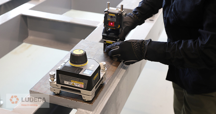
Download our 5 Element Machine Installation Infographic to help you outline 5 important elements of machine installation including Foundation, Anchoring, Isolation, Baseplate Level, and Flat plus Alignment. Together with our Easy-laser XT770G shaft alignment system plus the addition of our versatile XT20 laser transmitter, measure the straightness and flatness of machine foundations and bases with precision and reliability!
Related Blog: Top 10 Machinery Installation Issues
by Diana Pereda
We previously discussed in this series, Environmental Compliance Through Efficient Work Practices: Part 1. In this blog, we discuss goals for efficient work practices like proper alignment and belt alignment.
Upgrading tools and introducing more complete training should be part of any company’s operating plan, so we will see how much impact can be made by implementing solid information and work techniques that can impact the output of the machines, the reduction of stress of maintenance, and the achieved realization of environmental compliance.
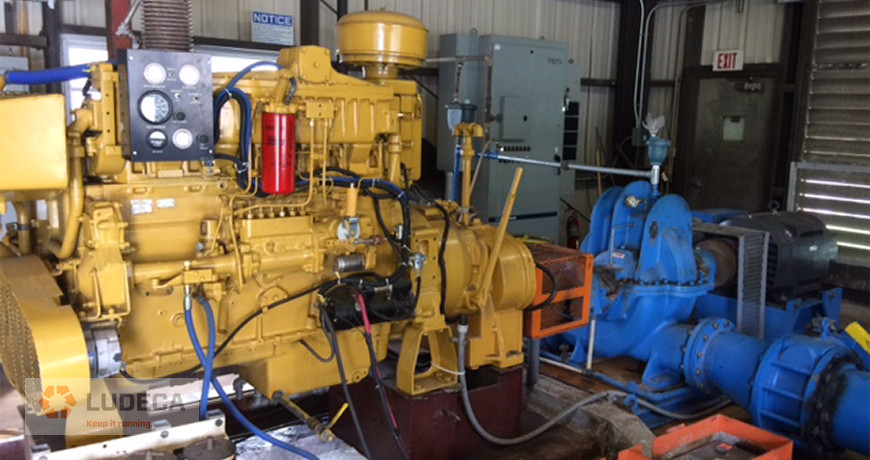
Proper alignment
In cases where an engine is running outside parameters for alignment, there is additional power consumption from the deformation of the coupling, the crankshafts, and the bearings. Having an alignment even a few thousandths of an inch outside of specifications can create enough bind to require 50-100 horsepower on a large engine. While that is not a lot for an engine rating 1780HP, it is enough to possibly put it over the permitted level, and incur a fine (in some states, that fine can be as much as $30,000 per day, back to the last time it was proven to be passing). Providing an accurate alignment procedure and using proper tools, we can expect to reduce that parasitic loss right at the point of power transmission and give that engine a cushion should the load be increased later for actual production demands.
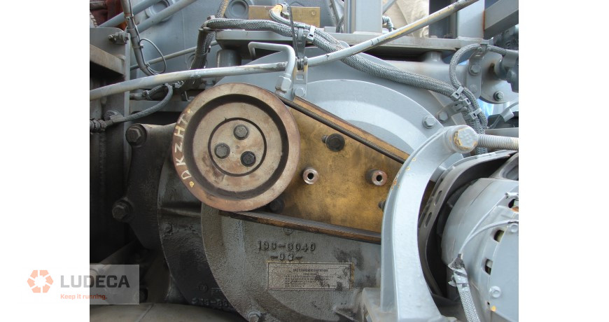
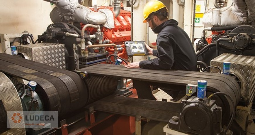
Belt alignment
A large number of these engines have huge cooling systems that are driven by the auxiliary drive of the engine. The belts that transmit this power can be massive, and leave the pulleys huge. Misalignment of these pulleys makes the belts deform and consumes power by constantly flexing. This also generates high working loads at the bearing that supports those pulleys. As the lubricant works harder within that bearing, it breaks down, and the bearing becomes harder to rotate. Again, we have a situation where the engine is being tasked extra to make up for these losses. Having an accurate system such as the Easy-Laser XT190 for proper pulley alignment can greatly reduce the power this sub-system requires for basic operation.
Stay tuned for my final blog of this series where I discuss proper adjustment of cooling fan blades and the right amount of lubricant needed for bearings!
Related blog: Guidelines for Proper Belt Installation including Sheave Pulley Alignment
by Diana Pereda
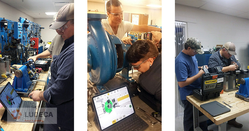
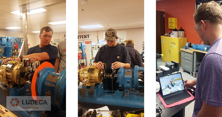
Midlands Technical College students are learning on the cutting edge of industrial training thanks to a dedicated instructor and a leading maintenance solutions provider.
Matthew Lester is a member of the Industrial Maintenance faculty in the School of Advanced Manufacturing and Skilled Trades at MTC in Columbia, S.C. In 2019, he worked with LUDECA to install a donated laser alignment system at the college. Since then, Lester secured funding that allowed for instrument upgrades to the donated system.
Now, new Easy-Laser XT series laser alignment systems and accessories are up and running. “Students, instructors, and experienced employees like the touch screen option and having access to the manual on the control unit,” said Lester. “Plus, the responsiveness and accuracy of the XT440 are unmatched.”
Thanks to tenacity and generosity, students at Midlands Technical College can work on five XT series laser shaft alignment tools and an XT190 belt alignment tool. MTC is at the forefront of maintenance reliability training programs in South Carolina.
To learn more about MTC shaft alignment courses, please click here. You can also contact Mr. Matthew Lester at: le*****@**********ch.edu.
Thank you Matthew for sharing your success story with us!
by Diana Pereda
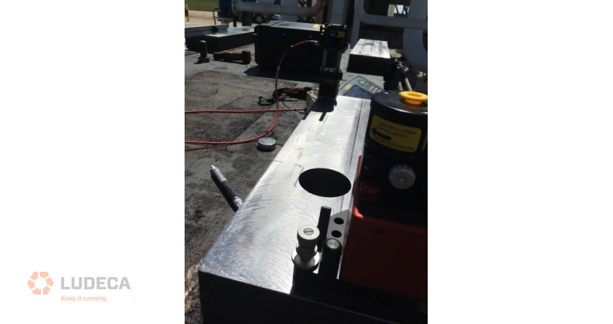
While it is now the norm to see technicians using laser tools to perform shaft alignment on rotating machinery at a plant or facility, it was not too long ago that sheaves and sprockets were still aligned with a string or straightedge. Although it is still common to see technicians break out the straightedge when aligning sheaves or sprockets, lasers for belt alignment are finally starting to be utilized more at facilities—even though that system may be a visual-type laser and target system. Download our 5-Step Sprocket Alignment Procedure – a simple and effective procedure for sprocket alignment of chain-driven equipment.
Those systems are easy to use and have the benefit of a steady and weightless laser line reference to help get your sheaves aligned versus the old straightedge or string technique.
As good as those systems are, however, there is still more to be desired…
A modern belt alignment system utilizes a position sensing detector or PSD that allows for repeatable measurements and real-time adjustments to be made. Additionally, the software that these systems can run on is easy to interpret and has the advantage of being able to generate reports. Which, in this reliability-centered world is a big plus.
Here are some advantages of modern laser belt alignment systems over the older visual systems:
- More accurate
- Simplicity in measurement and interpretation
- Repeatable
- Can produce reports
- Can justify their cost in energy savings alone
So, save time and money by using or upgrading to a modern laser belt alignment system!
Related Blog: The Importance of Belt Alignment
by Diana Pereda
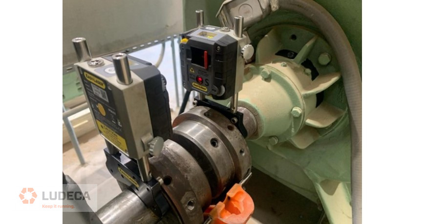
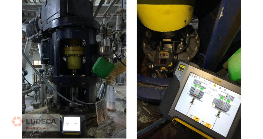
In vertically oriented shaft alignment, the objective is to make sure that the rotating axes of both shafts are lined up at the coupling during operating conditions. There are sometimes extra constraints such as plumb, which need to be taken into consideration. In this application, we have a typical vertical water condenser pump in which the pump housing has already been grouted into place.
The alignment of the motor shaft to the pump housing shaft needed to be inspected, and if necessary, corrected. The Easy-laser XT laser alignment system was chosen for this task. The compact wireless sensor units were installed on both shafts. Wireless is an advantage in this application as there are no cables to get tangled as the shafts are rotated. Once the sets of readings were taken, corrections were made by translating the motor to correct coupling offset and shimming on the motor flange to adjust the shaft angle. These corrections were calculated by the built in vertical alignment program of the XT laser alignment system. The corrections were monitored live with the system.
The results were documented and sent wirelessly via email to the customer. The result was that the alignment defects of the asset were identified, removed and documented in a short time.
Related Blog: How to Determine a Vertical Pump’s Natural Frequency
by Diana Pereda
This is a comment we hear all the time when someone buys a new laser alignment system. The assumption is that the cost of the system should magically make any alignment perfect, with little to no additional input from the technician. Nothing could be further from the case. In reality, the laser shows how inaccurate many work practices have become, as we depend more on technology. There are many factors that determine how an alignment job goes, and it’s time we discuss them. Without addressing these issues, the laser system will only continue to give us indications of how wrong things are.
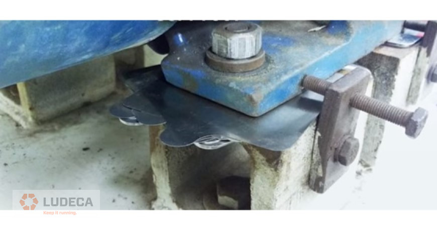
- Mounting surface: Most equipment manufacturers give a specification of what type of surface material and surface finish should be present for the mounting of the equipment they sell. Whether that is a fabricated steel base, a concrete pad, or even a grout box, the expectation is that it meets the installation guide for how well the footprint of the machine mates to that surface. The idea is to get the maximum contact patch of a clean foot to that clean base. Any irregularities, voids, or contamination can allow for unintended movement. And that movement could be happening while trying to perform an alignment, or even worse when the machine is running.

- Mounting evenness or flatness: Knowing that the surface is ready to receive a piece of equipment goes a long way towards a smooth installation. Often, shims from equipment previously in place are reused to mount a new component. The thought is that it worked for the last one, so it should be fine for this new one. Most of the time, this is simply incorrect. Most quality rebuild shops machine the feet of a motor or pump as part of the overhaul process, to make them all coplanar, or even. It makes sense to make sure the base is even as well. If you establish that the base is flat, or at least shimmed flat before the new equipment is put in place, the installation goes much faster, and the alignment is easy to perform. Soft Foot should be practically eliminated by doing this step. (More on that in a bit.)
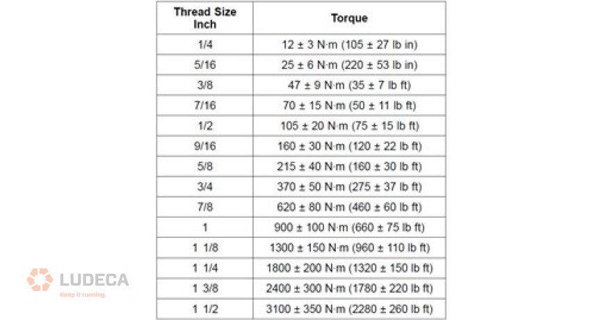
- Proper hardware and proper torque: OEMs are great at publishing specifications and possibly even giving recommendations for how to meet those specifications. What they count on is that everyone is aware of those requirements and how to achieve them. This means that when a torque spec is given, everyone from the design to the installation team should understand what size and grade of the fastener are required to meet that spec. Torque specifications for general fasteners are the same, no matter what industry. This means that if the bolt is 7/8″ in thread diameter, the general torque is 620Nm (or 460 lb/ft in old school terms), regardless of the setting. The only time these specs change is when it is in a specialized application, and at that point, specific torque charts are supplied. The main goal is to be consistent with the torque of hardware, so variables are not introduced from human inputs.
- Soft Foot: Ludeca has spent a large amount of time and resources trying to make the world more aware of soft foot conditions. We have videos, white papers, infographics, webinars, and in-depth diagnostics charts on the topic. The main takeaway is that if soft foot (i.e., machine frame distortion) is not eliminated, there is always an opportunity for unintended movement of the machine. It is simply not mounted correctly in some way even (including external pipe strain), and that situation is making it hard for the alignment to be done accurately, and hold the proper position when in service. When watching the outputs from a quality laser alignment system, if the tech sees numbers changing while tightening anchor bolts, that is an indication that soft foot is present. Visit our Knowledge Center for resources and tools to help you succeed when implementing and using our maintenance technologies.
- Second-guessing: The laser system is telling the tech one thing, but the thought is that the system is wrong. But something is occurring for the laser to give that information. Moreover, all of that information was gathered using inputs from the tech. The laser system is basically a computer with sophisticated optics attached, which means that “bad information in equals bad information out.” A better understanding of how the system calculates results makes it much easier to understand why those results are displayed. Training is the best way to resolve the confusion. Some companies buy laser systems, thinking that it will resolve all issues from alignment work and make the plant more reliable. In fact, this sometimes goes the other way. If the staff has been doing things a certain way for enough time that it becomes standard operating practice, the introduction of the laser might highlight how those practices were actually contributing to failures. Proper training not only shows the tech how to turn the system on but also shows how to achieve the best results for alignment. Sometimes, that training can identify issues that have been plaguing an operation for years, and actually, make life easier by not “fighting with the tool.”

Related Blog: What makes a laser shaft alignment tool accurate?
by Diana Pereda
Soft Foot has often been noted as the most inexact science part of the shaft alignment job. Historically, when people think of Soft Foot, they often want to neglect, ignore, or otherwise do everything possible to not deal with it. This is one of the traps that leads down the path of bad habits, bad alignments, and more problems down the line.
Shaft alignment can be thought of as two things:
- Aligning the shaft centerlines of rotation
- Checking for and correcting Soft Foot
Soft Foot, in fact, plays so much of a role in shaft alignment, that if one were to analyze the 5-Step Alignment Procedure below, one can see that Soft Foot appears in 2 out of the 5 steps. Therefore, Soft Foot can be thought of as almost half the alignment job.
5-step Alignment Procedure:
- Pre-alignment checks – including inspection and cleaning of machine supports
- Rough alignment – “eyeball clean” (with bolts loose) and Rough soft foot Loosen all bolts and “fill any obvious gaps”.
- Initial alignment – Get to within 5 to 15 mils at coupling or less than 20 mils at feet.
- Final soft foot – All feet less than 2.0
- Final alignment to tolerances and documentation
What is Soft Foot? Soft Foot is Machine Frame Distortion.
How does it happen? Soft Foot can happen from several things, including:
- Bent Feet
- Bad Bases (warped, uneven, flimsy)
- Dirt, rust, corrosion under feet
- Excessive or missing shims under the feet
- Pipe stress
- And any combination of the above…
What should be done about it?
A full and extensive diagnosis should be done on every machine foot to determine whether or not the tightening of that particular bolt is causing machine frame distortion, and thereby causing shaft misalignment or machine frame strain.
A few helpful tips to remember are:
- Minimize total number of shims under each machine foot to no more than 4 shims per foot.
- Make sure the area is clean, including machine feet, bases, shim packs, etc.
- Jack bolts should be backed off, so they don’t interfere with the soft foot check.
- When checking for soft foot, only one machine foot should be loosened at a time, and the deflection or movement at the shaft noted.
In conclusion, soft foot plays a big role in machine reliability and therefore should not be ignored. Laser alignment systems such as the Easy Laser XT series can help diagnose and correct soft foot.
Read: Common Causes of Machine Failure: #2 Soft Foot
by Diana Pereda
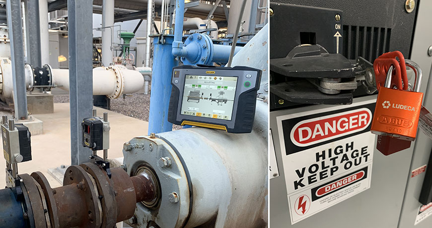
Before going on a trip, we typically plan ahead. What we are going to do, what we are going to pack, where we are going to go, and places to visit each day of the trip. When starting an alignment job, it is not that different. We must plan ahead. This means being ready to thoroughly clean the mounting base, having the right tools for the job at hand, and allocating the necessary number of hours to get the job done right.
Proper preparation for success can go a long way. Cleaning underneath the feet of the machinery will greatly decrease the chances of having a soft foot, thereby increasing the machine’s ability to respond accurately to corrections. Also, check under the entire machine for loose debris. Foreign objects under the machine can cause soft foot as the machine is lowered during alignment corrections even though the feet of the machine and shim packs are spotless. Another thing that should be considered during pre-alignment is having the right set of shims. These must be the right size for your application, corrosion-proof, and made from high-strength material. They should also be free of burrs, bumps, nicks, and dents of any kind. But first and foremost is planning for safety. Locking out/tagging out the machines is the VERY first step before starting the alignment process. Getting the right training to operate your laser alignment system and understanding misalignment will also save time and ensure success.
Let’s summarize a few of these important planning and execution steps:
- Lock-out and tag-out
- Thoroughly clean the mounting base and feet
- Visually inspect for foundation, grout, and baseplate defects, and wear and tear
- Make sure to have the right tools for the job
- Make sure to have the right shims
- Inspect and replace damaged shims
- Allocate the right amount of hours
- Have the right training
- Make sure your high-quality laser alignment system, such as an Easy-Laser XT770, is charged and all components and needed accessories like specialty brackets are there.
Download our 5-Step Shaft Alignment Procedure for a simple and effective procedure for shaft alignment of rotating equipment!
Related Blog: Pre-Alignment Checks plus Essential Clean-up and Preparation Tasks
by Diana Pereda
March 2021 – Pumps & systems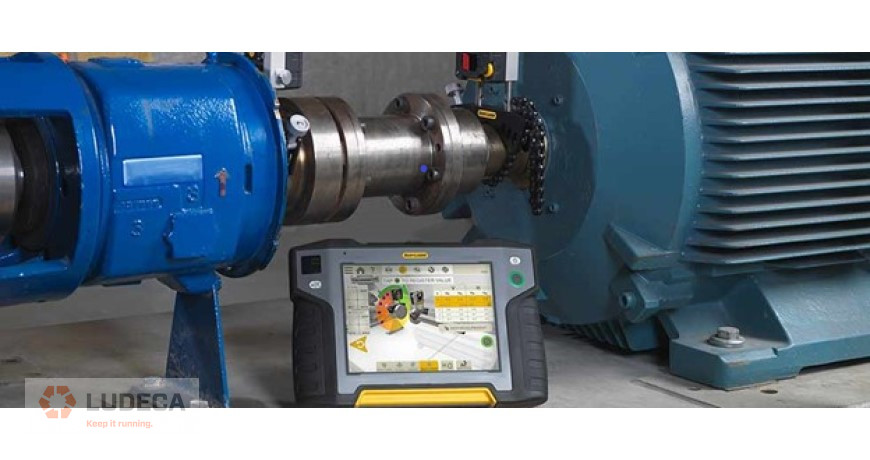
In olden times, when hard work beyond the ability of a few humans was needed, a horse or a team of oxen was the solution. Even greater power requirements were fulfilled by wind or watermills. This form of driving machinery lasted for centuries and the mechanical components involved required little in the way of alignment, beyond rudimentary good fits. When self-powered machinery was invented in the early 19th century in the form of James Watt’s steam engine, the pace of industrialization began to quicken. With this revolutionary power source, the volume of manufacturing increased rapidly and a greater demand for water and other fluids in industrial processes was created.
While early machinery often transmitted power via gear drives and flat leather belt drives, it did not take long for engineers to realize that directly coupling the driver to the driven machine would result in improved efficiency of power transmission with all the savings entailed therein. It is only with the invention of modern multiple V-belt drives with negligible stretching and slippage that the efficiency of belt-driven systems again rose to compete effectively with direct-drive systems.
In early days, speeds of rotation were slow and alignment of both belt-driven and directly coupled machines was traditionally accomplished by eyeing it, using a straightedge and feeler gauges. Good machining of surfaces and great care was usually all that was needed to obtain a satisfactory result. This modus operandi persisted through the 1940s. By the end of World War II, the United States was in a commercial position that favored industrial production: almost all of the world wanted manufactured goods, and the U.S. was a principal source for them. If someone wanted a car, a TV, or a sheet of stainless steel, it was likely made in the U.S. Global competition did not exist to nearly the extent that it does today, so cost-consciousness was not what it is today. Resources were plentiful, environmental regulation minimal, and craftsmanship excellent. Plants could afford to install standby machines for all critical processes and concrete foundations were poured a little deeper. People designed machines using slide rules. Today, computers trained to shave away every unnecessary ounce of metal do the designing.
In the 1930s, the average speed of rotation of an electric motor was 900 or 1,200 rotations per minute (rpm). Back then, the straightedge was king. Pumps had stuffing boxes, and when they sprang a leak, the mechanic simply tightened the packing glands to compress the braided cotton and asbestos packing rope until the leak went away. Often, the shaft was later found to be scored from the pressure of overtightening. As industrial production flourished and a wide range of new products were introduced, harsh chemicals demanded different containment approaches and mechanical seals became more prevalent. This demanded precision alignment. As technology improved, and Europe came online again with significant industrial production, the 1950s saw speeds of rotation increase to an average of 1,800 rpm. It was quickly discovered that as speeds of rotation increased, the need for good alignment also increased—not just in linear proportion, but exponentially.
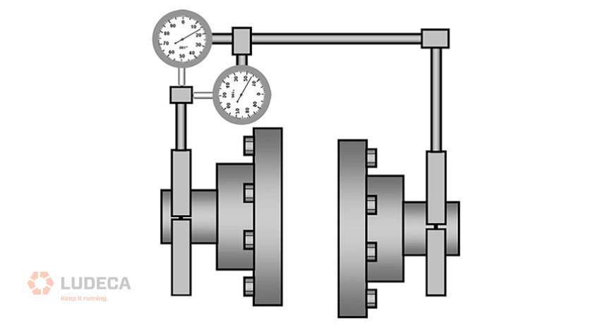
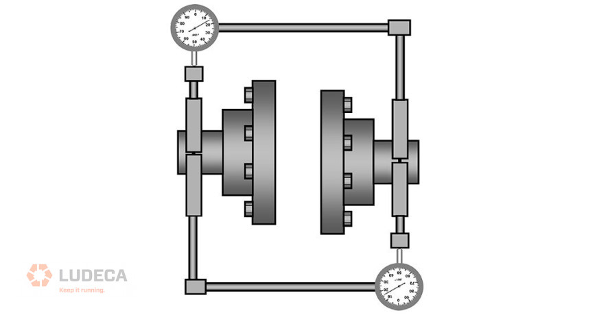
The straightedge could do a fine job with offset misalignment if used with care on coupling surfaces of well-bored couplings; but who could consistently guarantee such conditions? Yet, it was not good enough with regard to the angularity between the shafts. This was due to the limited measurement resolution afforded by eyesight over the short span of the straightedge across the coupling hubs. As apprenticeships and general craftsmanship declined, the assurance that coupling was machined concentric to the mechanical centerline of rotation, and that its faces were perpendicular to said centerline, or even that it was entirely round, waned. Also, foundations became weaker and not as flat as they ought to have been. Put simply, the alignment of surfaces via a straightedge or a dial indicator rotated around a shaft (not with the shaft) was no longer good enough. New ways to align the actual rotating centerlines of machines needed to be devised, and now the dial indicator (formerly strictly a machinist’s tool) came into its own. Its use by millwrights in machinery shaft alignment did not really take off until after WWII. Now the so-called “rim and face” method became king.
Click here to continue reading the entire article: Reduce Errors From Poorly Designed Machinery by Alan Luedeking
by Diana Pereda
When you are bolt-bound or base-bound on a critical machine train—usually one that is very difficult to move—it is not enough to just fix (make stationary) individual pairs of feet to obtain alternative shimming or moving solutions. You need even more flexibility, such as the ability to minimize moves across all the feet. The concept of stationary and movable machines is obsolete: all machine feet are movable under given circumstances, so it is essential to be able to find the minimum corrections necessary to align to any conceivable centerline, including fully optimized centerlines or centerlines optimized for any desired number and combination of fixed and movable feet. Such flexibility is imperative when working with machinery on the critical path. Therefore, look for this capability when selecting your next laser shaft alignment system.
For example, while trying to make the horizontal corrections on the misalignment below, one may run into a bolt-bound situation on the far-right machine. Moving the back feet of the motor over 100 thousandths may not be possible.
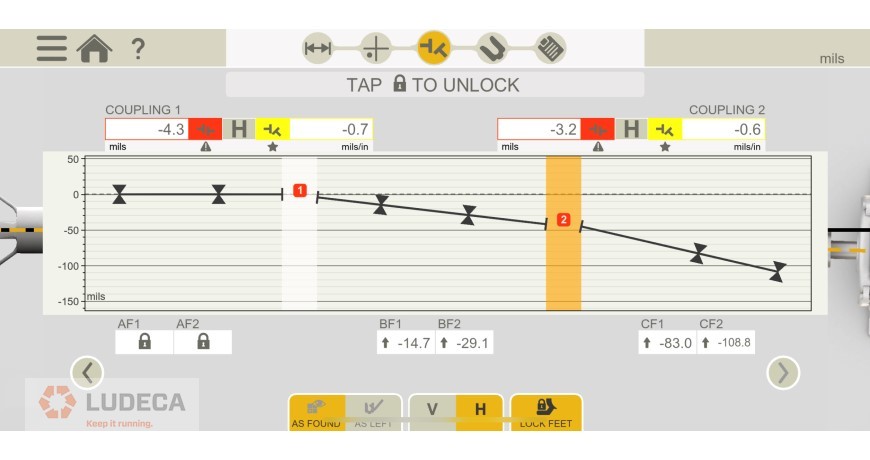
However, by making all machines movable and letting the laser alignment system optimize the alignment moves, we now have achievable corrections at each pair of feet:
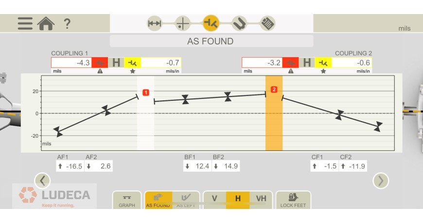
Notice that the back foot move of the motor on the far right dropped from an impossible 108.8 mils to a readily doable 11.9 mils.
Watch our Shaft Alignment Know-How: Bolt-Bound video to learn about the options of achieving alignment when in a bolt-bound or base-bound condition.
by Diana Pereda
When performing shaft alignment, the alignment is typically measured by rotating both shafts at the same time. Why is this? The reason is that the coupling is already installed, so it is convenient to do. The other reason is that rotating both shafts is the only way to measure the true rotating centerline of the shaft. Not doing so results in measuring only the surface alignment, which is subject to surface finish imperfections, shaft straightness, and hub concentricity issues.
When should you remove the coupling for an alignment? For starters, you typically need to rough-align a machine before installing a coupling. This can be carried out with a laser alignment system. Another situation is for machines that are difficult to turn with the coupling in place, which requires removing the coupling in order to take a measurement. Finally, some machines have shafts that are coupled through fluid drives, so rotating both shafts simultaneously could prove very difficult.
Uncoupled measurements are very similar to coupled measurements. The goal is to make sure the shafts are at the same rotational angle when a measurement is taken. To make this task easy, Easy-Laser implemented a digital readout of the angle on each sensor in all XT series shaft alignment systems. I have found this invaluable for performing an uncoupled alignment. One simply needs to rotate one shaft to a determined degree and simply look at the sensor to match both shafts to the same rotational angle; once this is carried out, a measurement can be taken.
Some uncoupled alignments are made difficult with a shaft that is hard to turn or requires a turning gear that does not allow manually matching the shafts’ rotational angles together. To greatly simplify this task, Easy-Laser has included an “uncoupled sweep” measurement mode. This mode allows the user to turn one shaft so the laser beam will sweep by the first sensor, and then turn the other shaft so that the sensor will sweep past the laser again. This sweeping motion causes a point to be automatically taken for each time the sensors sweep past each other.
Related Blog: Uncoupled Misalignment Measurement Made Easy
by Diana Pereda
The Problem:
The customer complained of excessive vibration on a wastewater pump driven by a diesel engine. Upon performing an alignment check, the machine shafts were found to be grossly misaligned. Furthermore, proper alignment was found to be impeded by a base-bound condition of the engine combined with external horizontal forces caused by the exhaust stack.
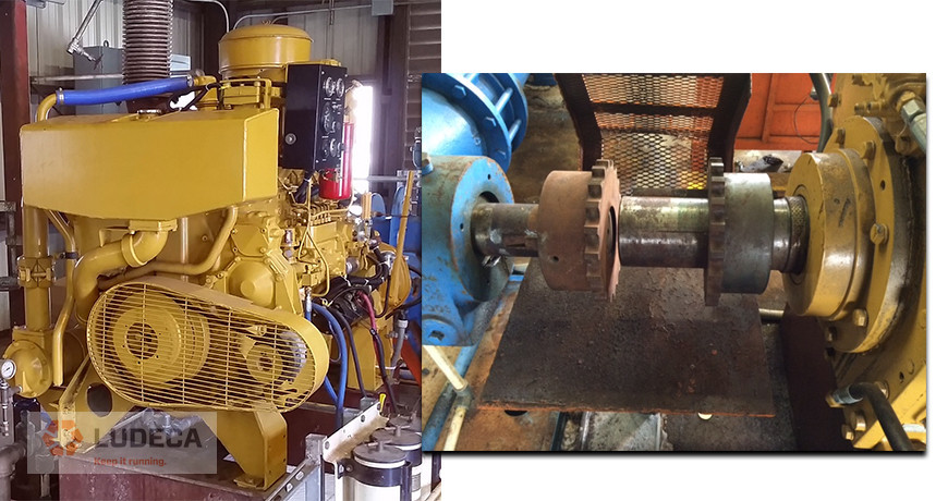
The Solution:
A base-bound situation means a machine must be lowered to bring it into alignment but insufficient shims are present under the feet that must be lowered to permit removing them in order to achieve the alignment correction. Using an Easy-Laser XT770 laser shaft alignment system, it was easy to determine alternative possible corrections to overcome the base-bound condition. Horizontal alignment was also achieved using the graphical display of machine shafts and the live-move mode of the alignment system.
Savings:
Easy-Laser XT770 made it possible to find positive (instead of negative) shim corrections to immediately achieve alignment to within tolerance. This meant that enormous time and expense were saved by not having to disconnect and remove the engine, as well as hire a machinist and portable milling machine to mill down the base-plate of the engine.
Watch our Shaft Alignment Know-How: Bolt-Bound motion graphic video to learn about the options of achieving alignment when in a bolt-bound or base-bound condition.
by Diana Pereda