When a failure occurs, one of two things happen:
- A Failure Analysis program kicks in to figure out what truly caused the failure in order to eliminate the condition that caused that specific failure. Or…
- The easiest thing to see gets blamed. That “blame game” can be influenced by factors that have nothing to do with that specific failure, like past experiences, mechanical prejudices (preferring one brand over another), personal differences (doubting another’s workmanship), and even possibly looking to sweep the whole problem “under the rug” to distance someone from that blame.
When it comes to the failure of a crankshaft, or any other component of a rotating assembly, alignment is one of the things often brought up, like a “low hanging fruit”. This is why having a proper procedure, such as our 5-Step Shaft Alignment Procedure is so important. Going through each step of that procedure will help spot and eliminate the defects that could cause the equipment to experience that failure. And once the work is completed, the documentation portion becomes a record of how the job was done in order to help with any Failure Analysis.
Let’s take a look at some failure modes and see what could have caused the issue instead of just saying, “must have been a bad alignment.”
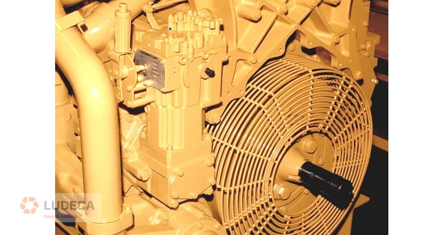
High Bearing wear at the front of an engine with Oil Analysis showing Tin, Aluminum, and Copper
Since this is nowhere near the coupling, alignment would be hard to blame, but there are other things to consider when looking for causes. Do the belts have too much tension? Was Soft Foot or Base Deflection overlooked? Has the Harmonic Balancer failed? Has the engine been reconfigured to run faster than originally rated and not have the supporting parts replaced to accommodate that increase in RPM? The bearings are coming apart and the cause must be found. Download an outline of types of Soft Foot including causes and corrections.
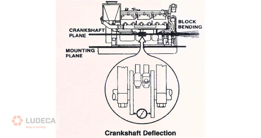
High Bearing wear in the middle of an engine with Oil Analysis showing Tin, Aluminum, and Copper
The problem is getting closer to the coupling so it cannot be ruled out, but it would need to be a large amount of misalignment to cause the bending of the shaft and a proper alignment procedure with proper tools and training would help eliminate that. What else would cause this condition? How about web deflection? Are the middle feet of the engine properly mounted and torqued?
High Bearing wear at the rear of an engine with Oil Analysis showing Tin, Aluminum, and Copper
Now we are talking a lot more about the alignment. Since the coupling is right next door, we have to be very aware of what that alignment looks like. How was the equipment aligned before, and what does the report show for an “As Left” condition? Has the equipment shifted or is the base and foundation degrading to the point that it can no longer support the weight and power delivery on this package? Was Thermal Growth calculated correctly and properly compensated for? All of these factors should be addressed with the application of a proper alignment procedure. Download an overview of 4 common thermal growth methods including advantages and disadvantages.
These are just some of the issues that have been discussed when a failure occurs, and in a lot of those cases, alignment got an unfair amount of the blame. If a procedure is in place to perform alignments correctly, and documentation has been properly archived, Failure Analysis should go much smoother to find the actual cause of the failure, instead of just going for the “low hanging fruit”.
by Diana Pereda
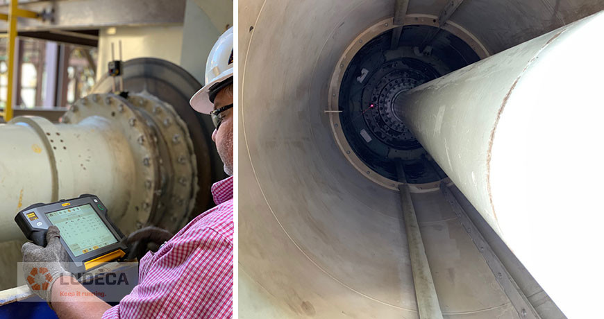
Marine propulsion alignment consists of ensuring that all bearings and rotational centerlines are set into a straight line as per the installation requirements. Depending on the vessel size, this means the machine, gearbox, clutch, support bearings, stern tube and struts should all make a straight line when the vessel is at sea. Proper propulsion alignment prevents unnecessary loads to the bores and prevents vibration due to back and forth bending cycles of the propeller shaft due to misalignment.
Ensuring this alignment is correct in dry dock is a physically demanding task! Ask anyone that has been tasked to perform such measurements and they will probably have stories of climbing in and out of the stern tube and though cramped spots—“Propulsion Alignment Yoga”.
With all the components that will need to be checked and re-checked after corrections, it is imperative that the alignment system be accurate and easy to use. Traditional marine propulsion alignments involve the use of a tight-wire that is stretched down the length of the propulsion line. While simple in concept, it is not without its woes. If a component needs to be removed, the line must be broken and reset. The wire can bounce due to wind and vibration. Finally, the operator must physically avoid coming in contact with the wire. In many cases, this is physically impossible and dangerous. It is dangerous because if the user was in a stern tube taking a measurement and the line broke, that high tension wire could seriously injure the person in the stern tube!
Fortunately, this task is made both safer easier with the Easy-Laser E950B laser marine propulsion alignment system. The concept is simple: the laser beam replaces the tight wire. The high accuracy laser sensor replaces the inside micrometer. The system digitally records the position of the sensor and touch probe with respect to the laser with a high accuracy (0.02mm). The result is quick and easy measurements of marine propulsion alignment. After the alignment is finished, the system creates a report for documentation showing that any alignment defects have been eliminated.
by Diana Pereda
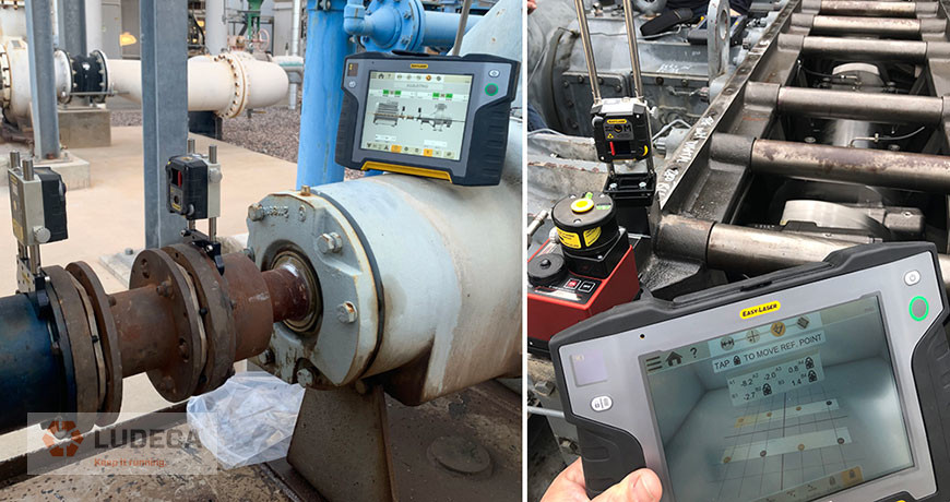
I recently participated in an alignment check done on a fracking rig. The misalignment between the diesel engine and the gearbox causes excessive vibration and damage to the u-joint. The goal for this particular alignment was parallelism between the gearbox and the engine.
The Challenges:
- The offset between the gearbox and engine was a little over 1 inch.
- Checking alignment between the engine and the transmission with and without the u-joint in place.
- Alignment is difficult because it has to be done on the rig which basically a tractor trailer, which means conditions can vary as the job is being performed.
The Solution:
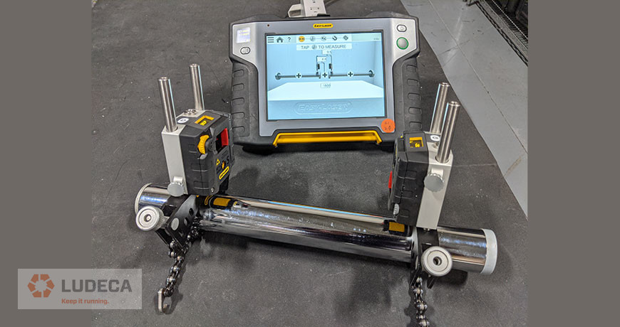
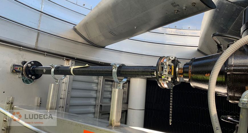
- Using the Easy Laser XT770 alignment system with the regular chain bracket set we measure with the u-joint in place. See Figure 1.
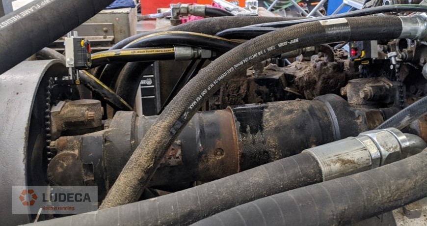
- Using the Easy Laser XT770 alignment system with the cardan bracket set, we measure without the u-joint in place, which allows mounting the components even in very tight spaces. See Figure 2.
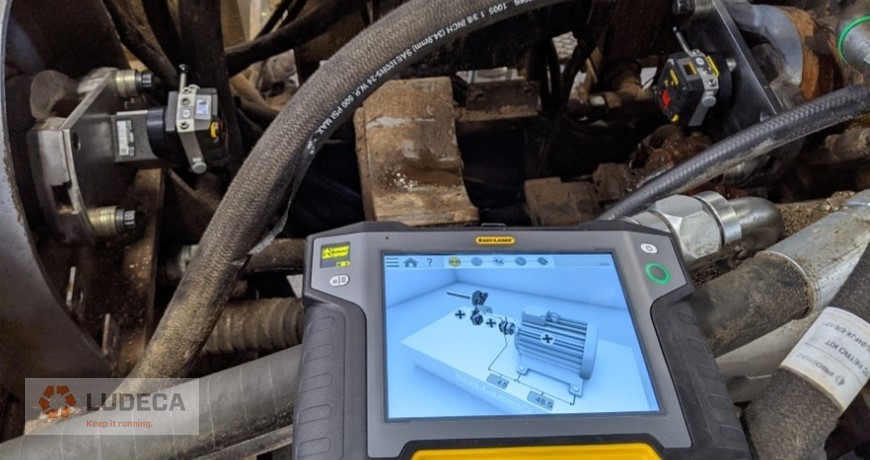
Using the Multipoint measurement mode allows measuring accurately even with the flexible frame of the tractor trailer. This measure mode allows us to increase the number of points collected at each arbitrary measurement position.
Benefits:
Accurate data can be easily collected even under challenging conditions in less time, allowing for better decision-making and corrective solutions to be implemented more efficiently.
by Diana Pereda
Motion Amplification is a camera-based full-field vibration technology that turns every pixel in the camera into a displacement sensor enabling you to see and visualize motion across the entire video. This opens up opportunities in visualizing an asset or system holistically instead of location by location often revealing information that would otherwise remain hidden. By combining this technology with other precision maintenance tools in the reliability toolbox you can better position yourself to address underlying issues and bring your equipment into a more sustainable operation. It is common for problems with machinery such as motor and pump installations to remain hidden or go undiagnosed.
For example, an improper or insufficient base installation can lead to excessive stress or looseness that ultimately leads to further faults or degradation in operating conditions. High vibration levels can be observed through contact sensors, but the problem persists even after the most common repairs are made, or perhaps the problems soon return. Often these issues are longstanding and go unmonitored and undiagnosed. These persistent issues can make it impossible to align a machine to the specified tolerances. Detecting issues through Motion Amplification can expedite the determination of the root cause issue. Once detected and repaired the equipment can then be precision aligned to bring it into the proper operating conditions and make it better suited to stay in that condition. By leveraging motion amplification and precision alignment technologies together, you can achieve a broader approach to diagnosing equipment and achieve more sustainable alignment conditions knowing the equipment you just aligned is not being affected by a fault still existing in the system. One size doesn’t always fit all and combining multiple tools in your reliability program to achieve superior reliability is just another way you can #keepitrunning.
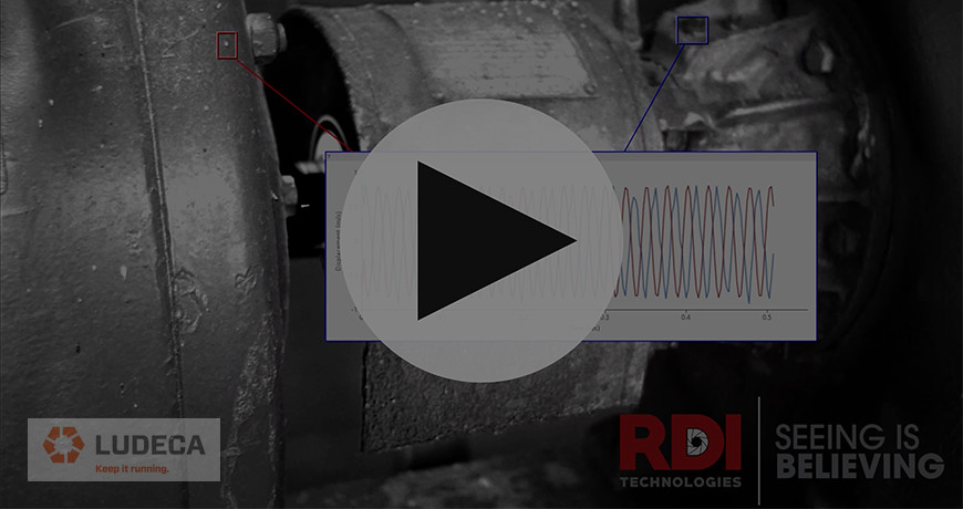
Motion Amplification showing Misalignment – Equipment setup: motor (left) and blower (right). The data on the screen is showing a measurement on either side of the coupling made from the video (red box corresponds to the red plot and blue box corresponds to the blue box) indicating the motion is 180 degrees out of phase in the vertical direction. This is also seen in the Motion Amplification video as one side goes up while the other side goes down.
Motion Amplification can be utilized in a multitude of use cases and to detect a broad number of faults. Among them are:
- Misalignment
- Imbalance
- Looseness
- Soft Foot
- Belt Slippage
- Structural Weakness
- Thermal Growth
- Resonance
- Bent Shaft
- Shaft Runout
- Flow Turbulence
- Excessive Piping Vibration
Thank you Jeff Hay with RDI Technologies for expanding our knowledge about motion amplification technology with us!
by Diana Pereda
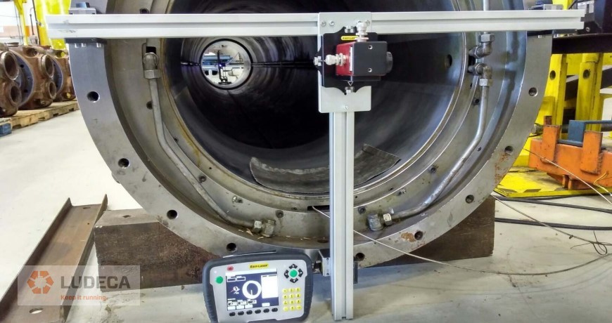
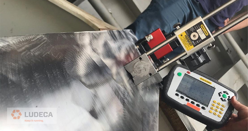
Marine applications often involve cramped locations and dirty environments which require that measurement systems be compact in order to be installed inside the vessel, but also be rugged and dependable enough to perform in these environments.
The application below shows the Easy-Laser equipment is being used in such an environment. Both the E-series and XT-series systems feature multi-role capability to handle the diverse needs of marine rotating equipment commissioning and maintenance such as flatness, straightness, squareness, level, and shaft alignment. They are used extensively in marine applications.
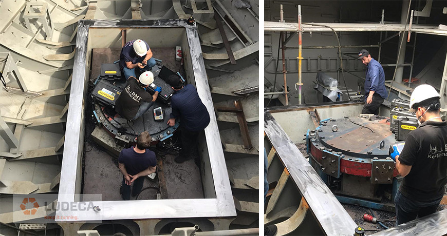
Measuring a baseplate in this environment is a challenge for some methods such as level or theodolite optics because these methods require consistent level, which is difficult on a floating vessel. With optical theodolite measurements, the scope itself can move due to the operator having to physically look through the scope and his or her weight potentially causing movement.
The ideal solution chosen for this application was the Easy-Laser E920. The issue of drift was removed by rigidly mounting the D22 laser to the most ideal location, the baseplate itself. The D22 rotating laser component projects a perfectly flat laser beam. A sensor is placed at the points of interest and can be measured remotely, removing the issue external factors causing any movement of the baseplate or laser.
The result was a fast and accurate measurement of the baseplate. A report was then generated to confirm that the alignment defects of base twist and distortion were removed from the installation. With this confirmed, the rest of the alignment could continue with the assurance that this step of the alignment process will not cause issues in the future.
Application photos provided courtesy of Ozan Onur Okumus, Energy Systems Engineer and Energy Manager of D.M.T. Makina. Bursa, Turkey
by Diana Pereda
As part of our laser shaft alignment troubleshooting series, we have discussed Laser Shaft Alignment Troubleshooting: Part 1 Repeatability and Laser Shaft Alignment Troubleshooting: Part 2 Response to Corrections. In this final part of the series, we will discuss The Pipe Test.
In this series, we’ve examined some of the causes of errors in laser alignment measurements that can be encountered and how to remedy them. If you’ve gone through each of the possible sources of error and are still experiencing problems, there is a simple field test you can perform to ensure the laser alignment system’s functionality.
THE PIPE TEST:
- Mount the measurement heads 6 – 10” apart on to a piece of pipe of a diameter no less than two inches.
- Start the horizontal shaft alignment program and enter the dimensions for the laser heads. Foot dimensions are not needed.
- If V-blocks are not used, take measurements by rotating the pipe with your hands.
- Take at least two separate measurements turning the shaft 360 degrees.
- The coupling results should be zero or very close to it if the system is performing correctly
Laser shaft alignment systems are reliable tools that produce highly repeatable results and simplify shaft alignment. That being said, technicians need to know that the measurements they’ve taken have minimal uncertainty and errors. That is where calibration comes in. Sending your unit out for periodic calibration checks will ensure the reliability of your system.
by Diana Pereda
We previously discussed misaligned couplings and how to reduce failures when ultrasound and alignment meet in “Ultrasound and Alignment Meet at the Coupling to Reduce Failures.” In this follow-up blog, we will discuss how ultrasound and alignment come together to improve belt-driven performance.
Misalignment in belt-driven equipment is one of the leading causes of failures throughout the industry. It breaks down machines and often costs your company thousands upon thousands of dollars in repair expenses and unplanned downtime. Imagine if you could combine two technologies you may already be using to prevent some of these failures. Ultrasound and precision laser alignment will make your maintenance department ever more proactive than ever before.
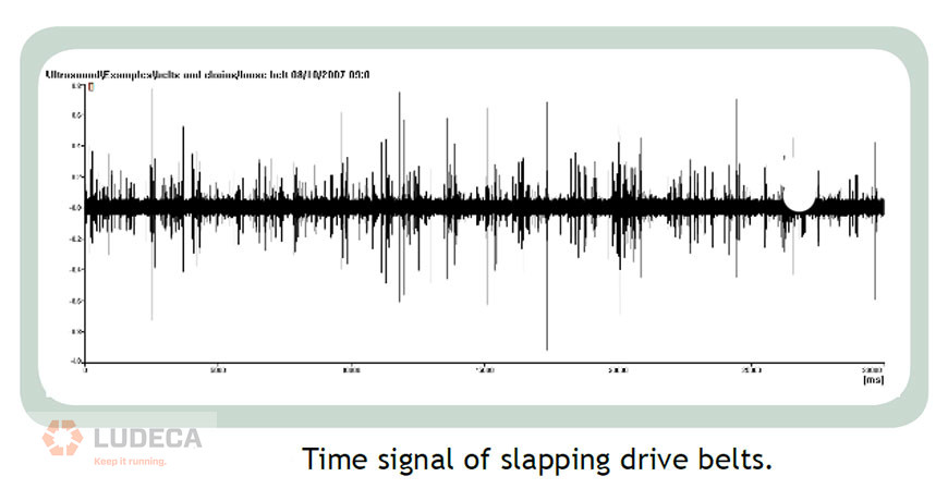
Belts can be too loose, too tight, or be running on misaligned pulleys. Loose belts will slap and produce a noise similar to whiplash. Tight belts and misaligned belts will generate additional friction which will again be audible ultrasonically. Figure 1 is a sample time signal of slapping belts.
An easy way to detect and prevent failures is to add your belt driven machines to your ultrasound routes. It will require a few extra measurements on each route and some trending. However, the benefits will far outweigh the costs. By being able to tell when a belt system needs to be aligned and properly tensioned before it breaks down, we can be more proactive and less reactive.
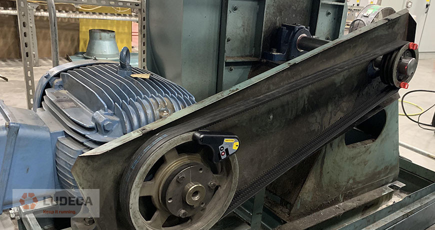
Once the imminent failure is being detected, we can address it with a realignment of the belt drive unit using our Easy-Laser XT190 pulley alignment system. It is easy to use and it will provide the user with a PDF report for documentation and accountability.
This blog was inspired by Uptime Magazine’s article, “There’s Something in the Air”, July 2009, pp. 48-53, written by Thomas J Murphy with SDT Ultrasound Solutions.
Download our 5-Step Sheave Pulley Alignment Procedure which provides a simple and effective procedure for sheave pulley alignment of belt-driven equipment.
by Diana Pereda
We previously discussed a lack of repeatability and identified some of the most common and easy-to-correct culprits in Laser Shaft Alignment Troubleshooting: Part 1 Repeatability. In this follow-up blog, we will discuss Response to Corrections.
Along with measurement repeatability, the laser alignment system’s ability to display the correct moves to bring the machines into alignment is crucial. If the machines do not respond to these corrections, you’ll be chasing moves throughout the alignment process – which isn’t fun!
WHAT IS RESPONSE TO CORRECTIONS?
Response to corrections is how the moves given by the alignment system work out.
If the results don’t reflect the moves made, the following can be the causes:
- Incorrect dimensions entered for the machinery. The alignment system relies on the correct dimensions being entered in order to predict the correct move amounts.
- Coupling strain can cause small deflections in the machine shafts that can misreport the correct shaft centerlines to the alignment system. Precise measurements of the rotational centerlines is crucial in determining the misalignment between them.
- Soft foot amongst other negative effects can hinder adjustment attempts.
In addition to the above considerations, environmental vibration, external stresses on the machines, and thermal effects can cause a lack of response to corrections. Identifying and accounting for these causes will make your alignment easier overall and help you get it done faster.
Watch our Shaft Alignment Know-How: Thermal Growth video to learn the importance of accounting for thermal growth on rotating equipment.
by Diana Pereda
Sometimes I will assist a customer on-site for shaft alignment. The first thing I will ask is, “what is the tolerance you wish to achieve?” Many times I would be given a specification, but sometimes I would be told “we need it aligned to 1 thou.” 1 thou I would ask, where? The answer would be “at the coupling and feet.” I would then reply, “Well that depends…”
Assuming soft foot will be addressed and that correct targets (deliberate misalignment, if needed) are given, there is just one thing that needs to be aligned. That is both shafts. They should be set for a proper offset and angle at the coupling point.
Watch our Shaft Alignment Know-How: Offset & Angularity and learn about the concepts of Offset & Angularity as they relate to aligning rotating equipment.
Feet adjustments are what you move the machine to align it to achieve tolerance at the coupling, therefore, feet moves have no tolerance. Feet adjustments vary depending on how far away or near they are to the coupling and to each other. Think of a laser pointer. If you aim it at a wall close to you and slightly angle it, the beam will slightly move. Should you aim in 20 feet away and slightly angle it, it moves much more. Depending on the feet positions, the precision of the adjustments will be generally more critical if they are closer together than if they are farther apart.
Regarding the coupling, the most important part of the alignment, you should consult your alignment tolerance table. For example, see the Easy-Laser XT’s built-in ANSI tolerance table below:
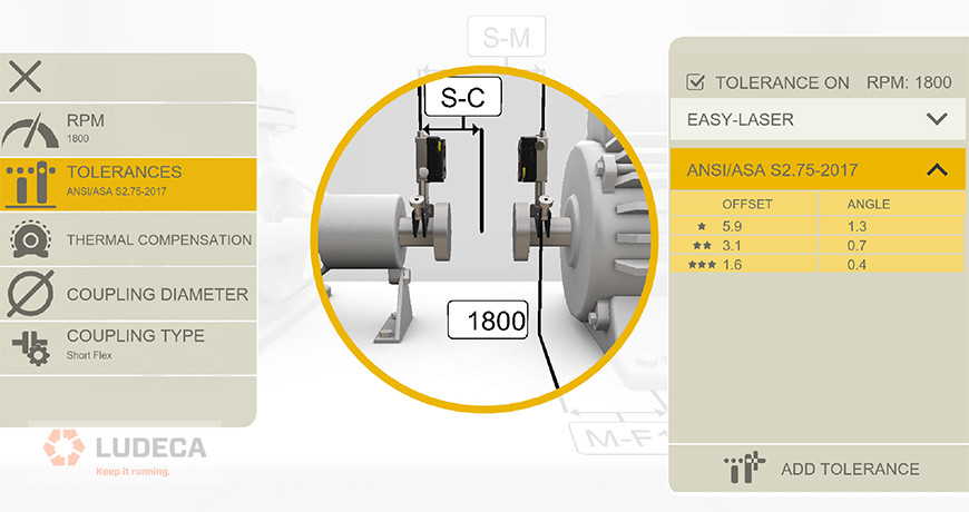
To achieve excellent (***) tolerance for coupling offset, you need to be within +/- 1.6 thou. Being within +/-1 thou can mean achieving either -1.0 thou or +1.0 thou, which is still within the excellent tolerance of +/- 1.6 thou. Being within +/- 1 thou offset at the coupling also means that you are within acceptable (**) and minimal tolerance (*) standards.
It is an entirely different case for the angle. The excellent tolerance is 0.4 thou/in, the acceptable is 0.7thou/in and the minimal is 1.3 thou/inch. 1 thou of variation can throw the alignment angle at the coupling completely out of alignment! Now is the spec unreasonably tight? Absolutely not! It is expressed in thou/in. If you had a typical 10” coupling, 1 thou out is equivalent to a coupling gap of 10 thou out, and this gets magnified for large couplings!
In conclusion, be careful about following the dogma of “1 thou” being acceptable. It is important to follow your required tolerance specifications.
Request your complimentary copy of our Shaft Alignment Fundamentals Wall Chart which highlights the ANSI/ASA Shaft Alignment Tolerances as well as information and guidelines for the implementation of good shaft alignment of rotating machinery, best practices, soft foot, tolerances, thermal growth, and much more!
by Diana Pereda
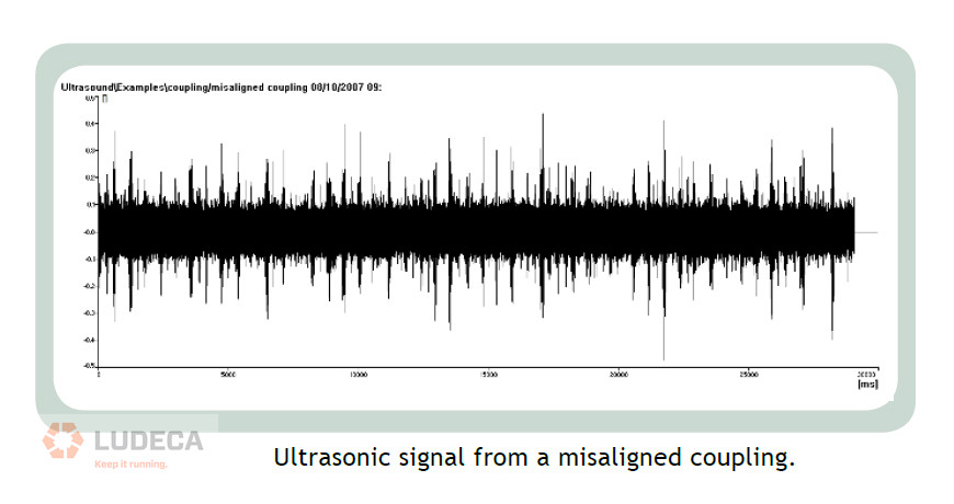
Misalignment in rotating equipment is one of the leading causes of failures throughout the industry. It breaks down machines and often costs your company thousands upon thousands of dollars in repair expenses and unplanned downtime. Imagine if you could combine two technologies you may already be using to prevent some of these failures. Ultrasound testing and precision laser alignment will make your maintenance department more proactive than ever before. For example, we all know couplings can be misaligned, and couplings can be loose. Infrared training tells us that a misaligned coupling generates heat. This heat is generated by the periodic friction caused by the coupling being squeezed with each revolution. Remember, friction we can hear. Therefore, a misaligned coupling will generate a periodic ultrasound signal like the one shown in Figure 1.
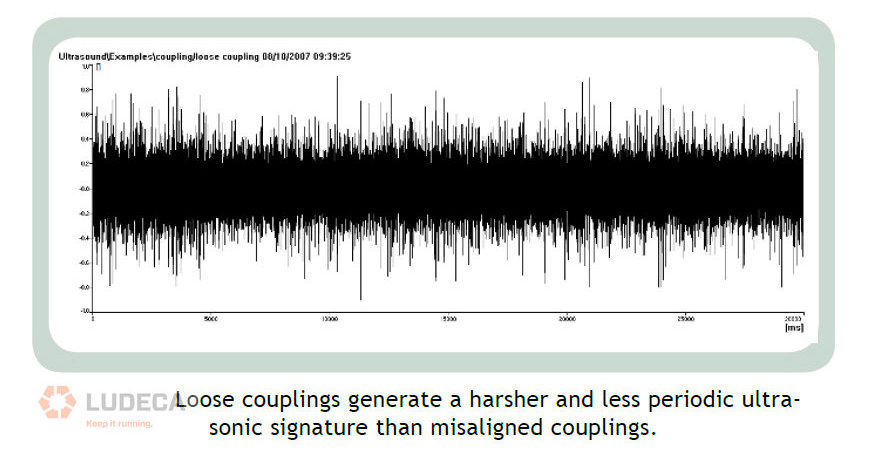
If you are already using ultrasound and laser shaft alignment, you are already there. All you have to do is add the coupling data point to your current ultrasound routes. This simple step combined with some trending will tell you when you need to check and correct the misalignment on the pieces of equipment along the route. Furthermore, a loose coupling will generate an ultrasound signal caused by the fretting of the coupling halves rattling. This fretting will be harsher and less periodic in nature than misalignment (see Figure 2).
Once the imminent failure is being detected, we can address it with a realignment of the machines using an Easy-Laser laser alignment system like the XT770. It is easy to use and it will provide the user with a detailed PDF alignment report for documentation and accountability.
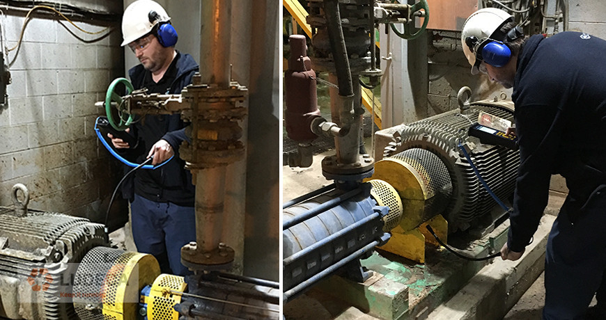
For more information on Ultrasound coupling, refer back to our blog, “Airborne Ultrasound Keeps Flexible Couplings Reliable” as shown above featuring our SDT340 Ultrasound Solution.
This blog was inspired by Uptime Magazine’s article, “There’s Something in the Air”, July 2009, pp. 48-53, written by Thomas J Murphy with SDT Ultrasound Solutions.
Download our 5-Step Shaft Alignment Procedure which provides a simple and effective procedure for shaft alignment of rotating equipment.
As an additional resource, we recommend watching, “Utilizing Ultrasound for Reliable Coupling” a presentation by Robert Dent with SDT Ultrasound Solutions
by Diana Pereda
What is repeatability?
Repeatability is the consistency of measurement results between consecutive sets of readings.
Laser alignment systems are capable of producing highly repeatable and reproducible measurements with just a few components attached to rotating machinery. When troubleshooting the cause(s) of lack of repeatability, it is helpful to try to identify some of the most common and easy-to-correct culprits.
Having a lack of repeatability can be caused by:
- Loose components such as measurement units or brackets. These components should be affixed to the shafts and should be tightened to prevent slipping or rocking of any kind.
- The measurement unit assembly should not rub on or strike any stationary component during a sweep measurement.
- Backlash effects due to play in the coupling should be minimized.
- If measuring using a sweep function, care must be taken to keep the rotation going in only one direction during measurement. Never let the heads rotate in the opposite direction.
- Use the appropriate measurement mode for the machines: i.e. sweep, multipoint, 9-12-3, etc.
Establishing repeatability of the alignment system is one of the most important steps in shaft alignment. It can make the difference between an easy-to-accomplish job or a job where you’re chasing your corrections.
Watch our Shaft Alignment Know-How: Repeatability video and learn more about the importance of achieving repeatability of measurements before making alignment corrections.
by Diana Pereda
Pump and Motor Skid packages are essential pieces of rotating equipment that come as a complete package, with both machines mounted on a “skid”. They are aligned at the factory and then shipped to the location to be installed at the facility. If the skid was aligned at the factory, is it unnecessary to align it after the skid is mounted to the floor? The answer is No!
While the skid package was factory aligned, even precisely using a laser alignment system, you can almost guarantee it will not be in an aligned condition after installation on the floor. One factor to consider is that this package probably travels long distances to reach its destination. It probably undergoes a lot of physical interaction during this process, such as being unpackaged, lifted, moved, hoisted, and set into place. In essence, it gets “bumped around” a lot.
Then, the skid itself is going to be placed on a concrete or steel support structure. Ideally, it is set level with jack bolts and gets get grouted into place for concrete installations. This should result in a solid, flat, and level installation. However, most installations involve simply bolting the skid directly to the concrete. For machine installation requirements, concrete is usually far from flat and level. It will most definitely twist or deform the skid frame as it conforms to the surface of the concrete. This will change the factory alignment of the machines which will then need to be addressed.
Shown below is such an installation where the skid was bolted directly to the concrete. Precision alignment is needed, this one features the Easy-Laser E710 laser shaft alignment system to correct the alignment starting from the base (soft foot) all the way through to the final shaft alignment. The fastest way to accomplish this is to follow the LUDECA 5-Step Shaft Alignment procedure. Once the alignment is complete, a report is generated showing the skid package was properly aligned.
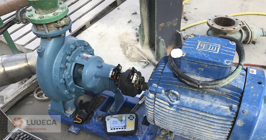
Ultimately, machines don’t care that alignment took place in the past. They care about what the alignment is during operation. Aligning pre-packaged skids after installation is non-negotiable for ensuring proper alignment.
by Diana Pereda
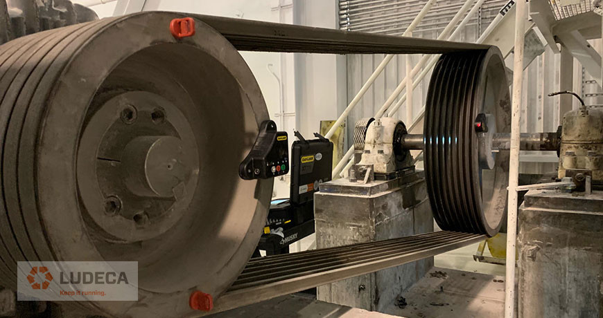
Maintenance departments periodically schedule maintenance checks on their belt- or chain-driven equipment in order to confirm that a good alignment exists between the pulleys or sprockets, especially if evidence of premature wear on the belts, chains, or sprocket teeth is detected.
Visual Pulley Alignment
D90, DotLine Laser, SheaveMaster, or SheaveMaster GreenLine laser pulley alignment tool is ideal. It indicates misalignment in all three degrees of freedom (axial offset, horizontal angularity, and twist angle) instantly.
Digital Pulley Alignment
If you need accountability and documentation of the alignment, then the Easy-Laser XT190 will be the tool you need. The XT190 can be connected to your phone/tablet via the Easy-Laser XT Alignment App or can also be added to your existing Easy-Laser® XT440, XT660, and XT770 shaft alignment systems. Both interfaces will provide a visual representation of the misalignment, the capability of entering tolerances, and a PDF report for documentation purposes.
3 Quick Tips for Precision Alignment
- Always mount your laser pulley alignment tool on the smaller pulley and the targets on the larger one, for maximum resolution.
- Ensure that the mounting surfaces (pulley faces) are free of dirt or rust.
- Don’t forget to verify the proper tension of the belts (or chains) after the alignment.
Download our Pulley Alignment Guide Plus 5-Step Procedure. This guide provides information for the implementation of good pulley alignment of belt-driven equipment including terminology, alignment methods, belt maintenance, storage, and tensioning as well as a 5-Step Sheave/Pulley Alignment Procedure.
by Diana Pereda
Chris Greene is currently a technical trainer with Ludeca and has spent years before that as a lead mechanic as well as other related industry roles. Chris has been involved with reliability and installation since 2008. Chris attributes his mechanical proclivity to growing up in and around in his parent’s foreign car repair shop and tearing apart and making a mess of things around the place.
“Machines are built by someone with intent. When you stray from that intent, that’s when the machines start telling you it doesn’t want to work right.” Chris has found technicians with a solid knowledge of a machine are much more effective than simply having a worker applying a specific tool or ‘turning a bolt.’
A major aspect of adhering to the correct operation of a machine is installing it correctly. The installation dictates how it will run. Finding a defect or identifying problems at the outset can mitigate a host of issues down the road.
Even so, Chris talks about how the industry as a whole has used the installation as a place to cut costs. The newer the machine, often the bigger the issues they are regularly facing. The overall lifespan of equipment is dropping, and Chris believes these oversights and cost cuts have a lot to do with this.
“Industries as a whole have tried to save costs and a large percentage cut on installation costs”
A good solid machine check or geometric measurement to ensure base plants are on the same exact same plane can significantly enhance the lifespan of the equipment. But it is more than just proper alignment. It comes down to aspects as diverse as the long-term suitability of the foundation. Many don’t take the time to look at basic issues like these. Are the anchors appropriately spaced? Do we have the correct base plates? These minor vibrations and movements due to little imperfections will take their toll over time.
On Documentation:
Chris suggests that keeping proper documentation can be a boon to equipment installation and care. Documentation helps take employees to take ownership of a job and helps to ensure you can track the efforts and match them to the suggested practices. It also helps with the root cause analysis of problems that arise. From a business management perspective, it also helps you to explain and layout how a business is to someone in an office.
Commissioning Groups and Specifications:
Generally, companies will have something called a commissioning group, and they verify these checks and sign off on them. People show up and often go through the installation checklist with you, and if you miss something on this checklist, you may not get a warranty until you check it. This process validates everything is done properly from the site to the torque of bolts. Download our 5 Elements Machine Installation Infographic which outlines 5 important elements of machine installation including Foundation, Anchoring, Isolation, Baseplate Level, and Flat plus Alignment.
Chris explains how over the years, tolerances have opened up since so many companies struggled to meet the older specifications. You can see the difference between the two levels of care when you examine the machines after a few years of operation. These little changes in optimal specs can show significant differences in short amounts of time.
Using tools like the ANSI/ASA alignment standard, and specifically, the standards dictated by the manufacturers, help you to see what the bare minimum standards for a piece of equipment are. You should ask yourself if you can do better than these. Better standards can only prolong equipment life.
The one thing to help with success?
Chris answers that you should understand the specifications and make sure you are installing equipment right and exceeding those tolerances. Management needs to understand that letting technicians have the tools and knowledge to do the job right can benefit machines and their lifespan greatly.
“A couple of loose nuts behind the wheel can wreck an entire facility.”
Spend the time to set a machine up correctly, take that extra effort to look ahead, and see what that next problem is before you build it into the installation.
Hear more from Chris Greene in this podcast by James Kovacevic and learn to understand how the correct installation of equipment will set the stage for optimal operational quality and longevity.
by Diana Pereda
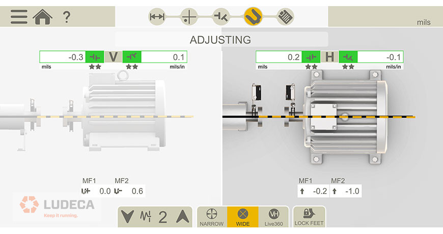
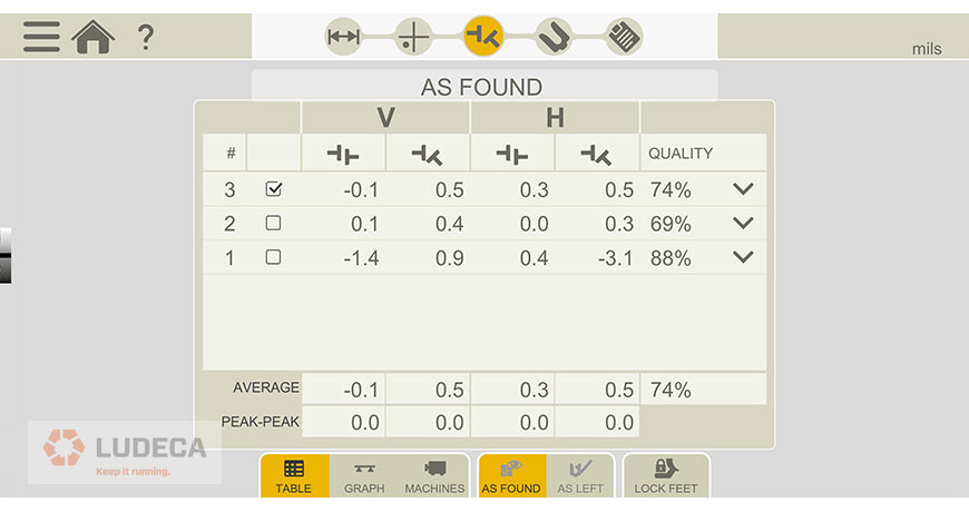
Often, when I get a report or a technical support call, if I see the user got a perfect “0-0”, I become immediately suspicious rather than celebratory. What I mean by “0-0” is that the coupling results or feet corrections (or both) are perfect zeros. There are times where that is possible, for example, this screenshot of the alignment that was taken out in the field as shown below:
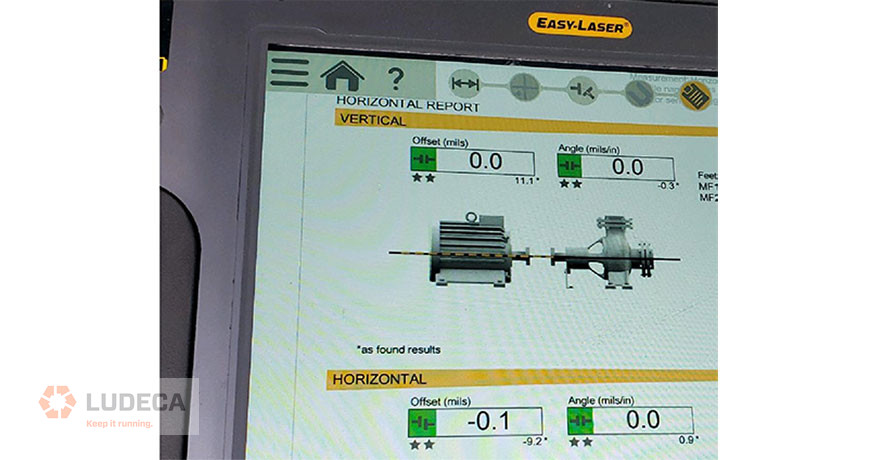
The numbers are close to zero, but not exactly zero. The point is there is at least some variation. Assuming the resolution is set to the nearest 0.1 mil, “0-0” would mean that that alignment is less than 0.1 mil, a very rare and impressive achievement!
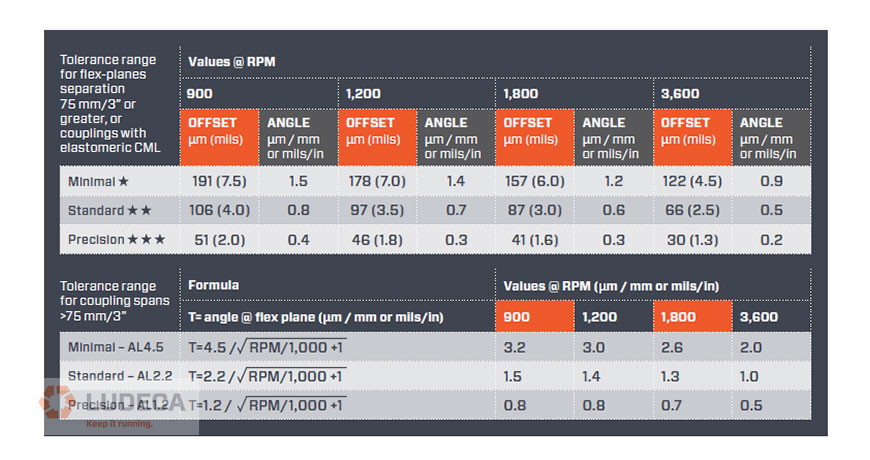
Is “0-0” necessary? The answer is no because you have a shaft alignment tolerance for a given speed of rotation. Lower rotation speeds require looser tolerances and higher rotation speeds have tighter tolerances. Tolerances are to be used to your advantage so you know when to stop the alignment. If the goal is perfect zeroes, it could be possible, but you will be working way too long to achieve a nearly impossible goal. We suggest the use of the ANSI/ASA S2.75-201 standard tolerance as shown below:
What happens if you do get “0-0” for your alignment? I would advise checking the following to make sure this was not a user setup error:
- Check the resolution. Is it set to 0.1 mil resolution (recommended)? If it is set to 1.0 or even 10.0, the lowest number will default to zero.
- Are you using the correct units? (i.e. metric vs imperial)
- Is the measurement shown to repeat in the measurement table? Is the alignment measurement reproducible?
- Were the sensors mounted on each machine shaft? Never mount the sensors on the coupling part that flexes, or you will get an incorrect reading. If you mount on the coupling only, this doesn’t represent the alignment between the machines; you will have an incorrect setup and most likely show perfect alignment.
- If you have a solid boss fit style rigid coupling, make sure the boss fit is separated to disengage the coupling with the bolts slightly loosened. This allows the misalignment to be measured. If the coupling is bolted, the shafts will be forced together, showing an incorrect near-perfect alignment.
Request your complimentary copy of our Shaft Alignment Fundamentals Wall Chart which highlights the ANSI/ASA Shaft Alignment Tolerances as well as information and guidelines for the implementation of good shaft alignment of rotating machinery, best practices, soft foot, tolerances, thermal growth, and much more!
by Diana Pereda
Correcting a shaft alignment problem brings a vast set of challenges to the workload of our mechanics, millwright, and engineers. Those issues could be in the form of physical constraints preventing movement or distortion from poor bases or pipe stress. They could be as simple and frustrating as soft foot or old bent shims. But, one of the most intimidating alignments out there is the spacer shaft, especially when it comes to extreme distances.
I am not an engineer—oh-oh, half of my readers just left—but for those of you still reading, I want to provide you with a few tips compiled by a few of us here at LUDECA to make your spacer shaft alignments with lasers easier. So, without wasting too much of your time, I refer you to the 5-Step Shaft Alignment Procedure.
Just kidding… sort of.
There are many different types of spacer shafts. So, what is a spacer shaft?
Picture 1
Generally speaking, a spacer shaft (spool, spider, jackshaft, or whatever you want to call it), is a coupling of some kind that spans more than 4″ or 101.6 mm between its flex planes. My goal in this blog is to provide five simple tips to help you align spacers without getting into the mathematical process. I’ll save those questions for the engineers. Keep in mind, these are suggestions for laser alignment of spacer shafts.
Spacer Shaft Tip 1:
Try to make sure you can square the two sensors to one another. By either using the inclinometers, lasers to targets, or really good eyesight – it tells you a lot if your sensors square up to one another. This seems like a simple or obvious tip (which is why it’s the first one) but, this also provides you with an indicator for TIP 2!
Spacer Shaft Tip 2:
There are two primary ways of aligning spacers: the Two-Step Method and the Single-Shot Method. Now that you can determine how bad your misalignment is – you can choose the method that fits best. The single-shot method is typically done when the alignment isn’t grossly out and the sensors would be mounted on the far ends of each spacer component. The two-step method is used when there is a significant amount of angle or offset to correct. The sensors should be mounted across each flex plane of the spacer individually to close the angle at each.
Picture 2
Spacer Shaft Tip 3:
Soft Foot. If you are following our 5-Step procedure you probably understood that I went a little out of order. However, we needed to know which components we were moving first, right? Now that we have a plan we have a procedure. Soft Foot matters, and it should be corrected and fall within the allowable tolerance. Use this time to also correct any challenges that can be identified visually (clean the base, good shims, etc.) You may want to take a look at our Soft Foot Find and Fix Procedure for an outline of types of Soft Foot including causes and corrections.
Spacer Shaft Tip 4:
Know your tolerances. There are 1,001 blogs and articles on spacer tolerances on the web. The best thing you can do is know what your tolerances are for that specific alignment. Yes, spacer tolerances can be more forgiving in terms of the required corrections at distances. However, there are many ways to represent those spacer tolerances. You could have a specification that is Angle/Angle or Offset/Offset or a combination of those. Make sure you are aware of the required values and representation.
Spacer Shaft Tip 5:
Patience. Don’t rush to get it done. Do it right so you don’t have to do it again.
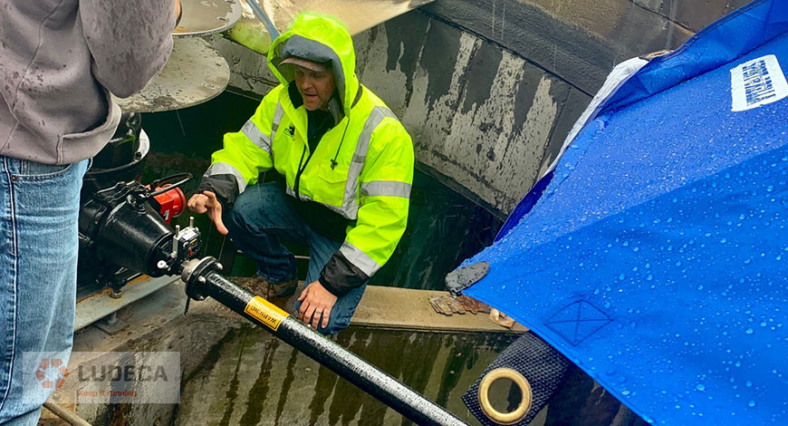
Picture 3 and 4
So, when you find yourself facing a spacer shaft, spool piece, or jackshaft, take a deep breath and follow the same rules of alignment that experience has taught us. I would also like to thank Joel Chapman from Entech Sales & Service Inc. for a lesson in cooling tower alignment in the rain (the umbrella was for me, not the laser, it was very nice of him – picture 2). And, thank you Richard Armstrong of TRACE Reliability, a LUDECA, INC. solutions provider who makes our customers a priority. He shared pictures 3 and 4 of an ID Fan in Louisiana that measured 289” inches from sensor to sensor.
by Diana Pereda
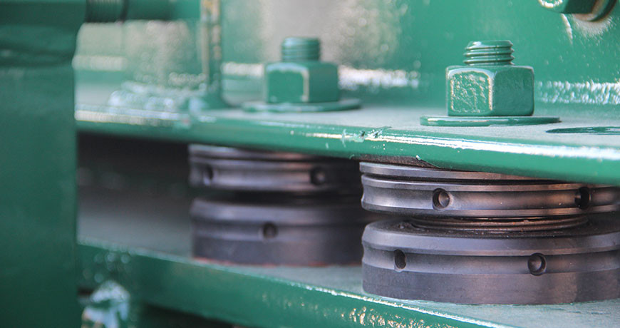
Adjustable chocks have been around for years and are a useful way to accomplish parts of machine mounting and alignment. In some circles, they have either a great or bad reputation. A lot of that reputation may depend on the application and how the chocks were installed.
Adjustable Chocks vs. Shims
First, let’s discuss why a company might want to use an adjustable chock for machine mounting, instead of shims:
- Adjustable for height. This means not having to stock lots of shims, in different sizes and thicknesses, to accomplish vertical adjustments in alignment.
- Spherical top part. This accommodates issues with feet not being parallel (up to 4 degrees for some manufacturers) with the foundation or skid which eliminates the need for step shimming.
- Easy Soft Foot corrections. When an air gap is found, simply fill the gap by adjusting the chock to fill the gap. (Zero Soft foot)
- Reduced inventory. Instead of several shims in a kit for each piece of equipment, just reuse the existing chock for adjustments.
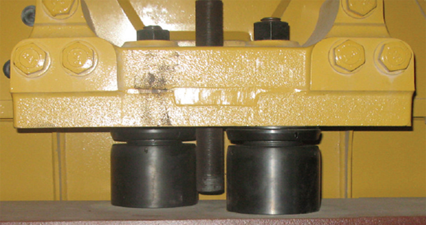
Now, let’s discuss why a company might not want to use an adjustable chock for machine mounting, instead of shims:
- Lack of contact surface between mounting foot and base. How can this round element take the place of a full-footprint shim for secure mounting?
- Transmission of Energy. Without the solid contact of that full-footprint shim, the energy will never be transmitted to the Inertia Block in the base; therefore, the equipment will shake itself to pieces.
- Locked up chock. Once they have been in service for a while, they lock in place and have to be replaced for future alignments.
- Loose chock. Upon inspection, the chocks have been found to be rotated down under the foot, and there is a gap/Soft Foot condition.
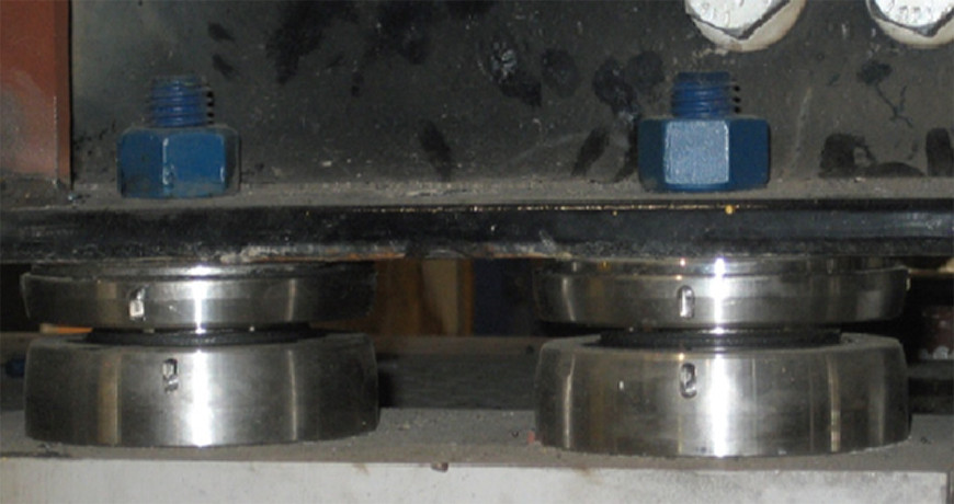
The Cons of Adjustable Chocks
By looking at each of those concerns, answers can be found for how to mitigate the concern and better understand how adjustable chocks can (and cannot) be used. The design and engineering of these devices make them suitable for most applications, but not if selected and used incorrectly.
For the issue of lack of surface area under a foot to the mounting base, looking at the product catalogs show any number of configurations to increase the surface area. Using more than one at each foot, or having two under a foot but staggered. The simplest rule to use is to use the largest chocks that can fit, but with a catch. The top surface must cover at least 75% of the surface area of the mounting foot, and the bottom surface must have 100% of its surface area in contact with the base. Both of these surfaces must be clean.
This leads to the next issue, the transmission of Energy. If the correct size of the chock is selected, and the above rule for coverage is observed, then the Energy will transmit through the body of the chock just fine. The other thing to watch for is cleanliness. Both the bottom of the mounting foot and the top of the base should be clean – reasonable steel-of-the-truck finish (corroded, excessive mill scale, or moon crater need attention, with a minimal primed surface for corrosion purposes. Any amount of paint, dirt, or debris can make for an uneven surface that could result in the bottom of the chock not sitting squarely. Sometimes, a bit of light sanding can go a long way towards promoting proper machine mounting. Check with chock manufacturer for surface finish recommendations.
Now, for the locked-up chock. Oftentimes, comments are made that the machine being aligned is unable to be lifted by the adjustable chock. This is a misconception. The threaded chock is designed to lock under load. It is NOT designed for lifting or lowering the equipment. Normally, equipment that is designed correctly will have vertical jack bolts, and this is what is used to establish the correct elevation for the machine, or, in their absence, use a hydraulic pancake jack or other suitable lifting devices. Beyond that, finding the chocks unable to rotate after being under a piece of equipment can usually be attributed to dirt and debris in the threads. It is a very common practice to lift the equipment on the vertical jack bolts just enough to remove the chocks. Thorough cleaning in a general solvent can remove the particles that restrict movement. After the cleaning, a thin coat of appropriate lubricant (often a specific compound recommended by the chock manufacturer) will help ensure movement. Protecting the cleanliness of the chock after alignment can be accomplished with a heavy protective spray. Anything that seals moisture and debris out is good, as long as it does not trap moisture (just to note: whatever you put on it will need to come off at some point to allow the chock to be reusable – be judicious or better yet contact your chock supplier).
Lastly is the concern of loosened chocks, which has been a topic of much discussion lately. The easiest way to explain this problem goes back to proper training. The technician performing the alignment needs to be mindful of how an adjustable chock is designed to work. The function of that chock is to support the machine. Prior to torquing the hold-down bolts, the machine needs to be resting on the chocks, not on the jack bolts.
The procedure boils down to using the jack bolts to establish the correct elevation, spinning all of the adjustable chocks up to firmly contact with the bottom of the machine, and then perform the final tightening. (Fit all chocks at the same time!!) Back off all lifting and lateral adjustment jack bolts FULLY, then tighten the anchor bolts to the proper torque in the sequence specified by the equipment OEM
Do not tighten the anchor bolts with the jack screws or lifting bolts under load!
The purpose of adjustable chocks is to facilitate proper mounting of equipment, more efficient alignment operations, and a viable replacement for traditional shims. While they might not work for all applications, with proper implementation chocks can work for 90-95% of applications where larger spacing between the machine feet and the mounting base is required; rather than inserting a big pile of shims, a chock can make life easier for the technicians performing realignment. This requires an open flow of information from the design and installation of the equipment, all the way through to the day-to-day maintenance.
This post was written in collaboration with www.machinerymountingsolutions.com
by Diana Pereda
The consequences of positional change due to thermal growth in machinery as it pertains to shaft alignment are well documented. Methods for determining these changes and compensating for them are not only essential to the reliability of machines but can prevent catastrophic failure. It is therefore of great importance that these methods be carried out as carefully as possible—minimizing human error as much as possible to ensure effective results.
One often-overlooked consideration when performing shaft alignment measurement is the temperature and thermal stability of the very components used for these measurements. Brackets, lasers, sensors—all components that are susceptible to thermal growth. Changes in the intensity of sunlight, large shifts in ambient temperature during the job, and performing measurements too soon after bringing the components out to the machine can all lead to lack of repeatability and improper shaft alignment corrections.

You can minimize the effects of these conditions in various ways:
- Always allow a suitable amount of time for the alignment system to acclimate to the environment in which you will be performing the measurements. For example, if the equipment is moved from a warm office or truck to a cold environment and measurement is begun immediately without giving the temperature of its components enough time to stabilize, performing the shaft alignment will be a bit like trying to hit a moving target. The brackets and/or laser and sensor housing will still be physically changing in dimensions until stabilization has occurred.
- If sunlight conditions are unstable where you are working try to keep the alignment components shielded from the sun. Direct sunlight striking the laser housing of a shaft alignment system can have an adverse effect on the reliability of the readings during a measurement.
- Keep portable heaters and air conditioning units away from the area. It is natural to want to work in a comfortable environment, but the unstable air currents caused by heaters or a/c’s can wreak havoc on measurement repeatability.
- And one more: if a heat source is intense causing heatwaves in the path of the laser beam, thereby distorting or refracting the laser beam and affecting your repeatability, a simple fan to blow air through that area can help to stabilize conditions or provide a uniformly turbulent atmosphere for the laser to travel through, allowing its true position to be accurately averaged.
Observing these principles while performing shaft alignment readings will allow you to achieve more stable and reliable results and thus help you to #keepitrunning.
For more information, check out our Shaft Alignment Know-How: Thermal Growth and learn the importance of accounting for thermal growth on rotating equipment.
by Diana Pereda
Soft Foot Measurement – It really is important!
On a recent visit to a power plant, they asked me to help them align a pump with their new EASY-LASER XT Alignment System. It was a machine they had previously aligned with dial indicators, which they thought was “pretty good”. The initial measurement showed a vertical offset of about 7 mils, so we removed all the shims and measured soft foot. The results are shown below.
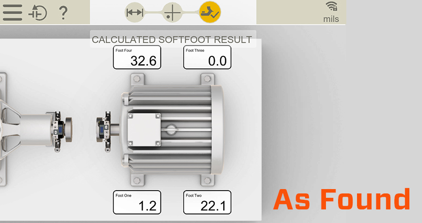
As you can see, there was a significant issue. We probed and found gaps under both the indicated feet. The foot showing 32.6 mils showed a parallel air gap, whereas the foot showing 22.1 mils had an angular gap that required step shimming.
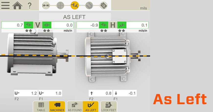
Once the soft foot was corrected we continued with the alignment, and achieved excellent results.
In a later conversation, I learned that the motors had been too high for the pumps when installed, so the contractor ground down the feet with a wheel grinder! That explains the soft foot issue!
Bottom line, ALWAYS check soft foot. Not only does uncorrected soft foot make the alignment more difficult, it introduces stresses to the machine thus reduces reliability.
Download our Soft Foot: Causes, Characteristics and Solutions white paper for additional information that explains in depth the causes and characteristics of soft foot conditions and how to diagnose and solve them.
by Diana Pereda

Many shafts have keyways cut into them to hold the coupling. “Keys” are pieces of square metal stock inserted to hold the hub in place.
If there are two (2) keys, one on each side of the coupling, you should not “align” the keys across the coupling. Instead, it is very important to ensure the coupling mass is balanced during installation. The mass of a key is balanced by setting the two keys 180 degrees apart from each other. If the keys are set on the same side, the coupling will induce a mass unbalance situation.
Often a vibration report will note a misalignment condition, but precision alignment techniques will not find any issue. This can lead to friction between the vibration analyst and the millwright. Keep the keyways 180 degrees apart. You will help improve the life of the coupling and keep the vibration low.
by Diana Pereda