The use of acoustic imaging cameras is expanding because more teams now face the same operational problem in very different settings: they know something is wrong, but they still need to locate the source quickly, from a safe distance, and with enough visual evidence to act on it. That pattern shows up in compressor rooms, substations, EV assembly lines, composite shops, hazardous areas, and engineering labs alike.
What makes acoustic imaging useful across industries is not that it replaces every existing test. It is that it helps narrow the search space. When a technician, engineer, or reliability team can see where airborne sound energy is concentrated, troubleshooting usually becomes faster, more repeatable, and easier to document.
This article is an application map rather than a product roundup. It covers the 10 workflows where acoustic imaging cameras tend to create the clearest operational value, then compares which deployment model fits which kind of job. If you want a fundamentals refresher first, start with What Is an Acoustic Camera? and How Acoustic Imaging Works.
What acoustic imaging cameras do best
Acoustic imaging camera: a microphone-array-based inspection tool that turns airborne sound into a visual map, helping teams localize likely leak paths, discharge sources, abnormal noise, or other acoustic anomalies more efficiently.
In practice, acoustic imaging is strongest when teams need three things at once: localization, scan efficiency, and visual confirmation. Instead of checking one point after another, the operator can scan a wider area and see where sound energy is likely concentrated. That changes the troubleshooting workflow in a meaningful way, especially when manual search time is more expensive than the final validation step.
That last point matters. Acoustic imaging does not replace every certified or process-critical confirmation method. In leak-tightness work, teams may still rely on pressure decay, tracer gas, or immersion testing. In electrical maintenance, they may still need established diagnostic and safety workflows alongside acoustic surveys. The value of acoustic imaging is often that it makes those workflows faster by showing where to investigate next.
Interpretation also matters. Reflections, beamforming artifacts, and site geometry can influence what appears on the display, especially in reflective or crowded environments. That is one reason it helps to pair practical application knowledge with basic method knowledge, such as the guidance in Acoustic Imaging False Positives: Reflections, Beamforming Artifacts, and How to Avoid Them.
How to read this top 10 list
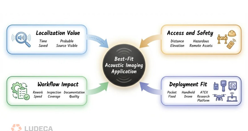
This list is not ranked by market size. It is organized around where acoustic imaging usually produces the clearest workflow benefit. We used four filters:
- Localization value: Does seeing the probable source area save meaningful troubleshooting time?
- Access and safety: Is distance, elevation, or environment making direct inspection harder?
- Workflow impact: Does the result improve rework speed, inspection coverage, or documentation?
- Deployment fit: Is there a clear match between the use case and a handheld, ATEX, fixed, drone-mounted, or research-oriented system?
That framing helps keep the discussion practical. Acoustic imaging is not equally useful for every sound-related task. It tends to win where conventional methods can confirm that a problem exists, but still leave the team asking where the issue actually is.
Thanks to Crysound for sharing this educational blog! Click to continue reading, here’s a preview of what you’ll find:
- The top 10 applications
- Which deployment model fits which application?
- FAQ
- Conclusion and next step
by Diana Pereda

In today’s world, improving uptime, reducing energy losses, and enhancing safety are top priorities for maintenance and reliability teams across all industries. Acoustic imaging technology has emerged as a powerful tool in predictive maintenance, enabling professionals to quickly detect issues that are invisible to traditional inspection methods. By combining sound and visual data, this technology helps identify problems early and safely, before they lead to costly failures. Below are five key benefits of using acoustic imaging in industrial plants:
1. Versatility
One of the biggest advantages of acoustic imaging technology is its versatility. It can be used across a wide range of industrial maintenance applications, including compressed air systems, to conduct electrical inspections, and for mechanical equipment monitoring.
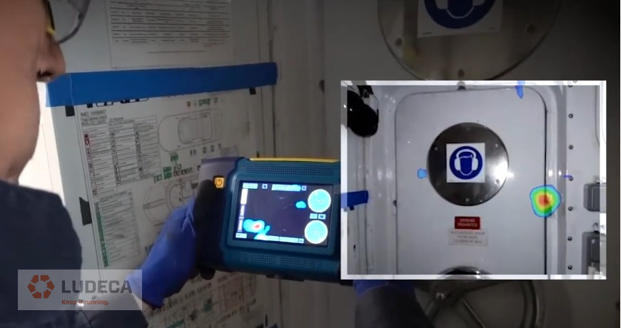
By providing a real-time acoustic heatmap, technicians can pinpoint the exact source of anomalies even in noisy environments. This reduces troubleshooting time and improves inspection accuracy. Unlike traditional methods, non-contact acoustic inspection allows for safer assessments from a distance, minimizing the technician’s exposure to hazardous conditions.
2. Energy Savings
Compressed air and gas leaks are among the most expensive and overlooked inefficiencies in industrial processes and facilities. Acoustic leak detection enables teams to quickly locate compressed air leaks, vacuum leaks, and gas leaks without shutting down operations.
When paired with a leak cost calculator in Ludeca’s CRY8128 Acoustic Imager, this technology becomes even more powerful. Maintenance teams can not only detect leaks but also quantify its financial impact in real time. This helps prioritize repairs based on ROI and supports energy-saving initiatives.
Early detection using ultrasonic leak detection can save thousands of dollars annually while reducing carbon emissions, making it a critical tool for energy efficiency and sustainability programs.
3. Safer Inspections
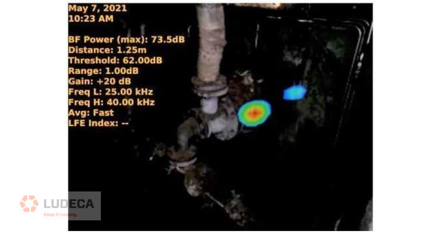
Electrical failures are a major cause of downtime and safety incidents. Acoustic imaging for electrical inspection can detect partial discharge (PD) phenomena such as corona, tracking, and arcing—often before they become visible or catastrophic.
Download our Electrical Faults: Signs and Signals with Airborne Ultrasound infographic for a basic guide to electrical faults detection using ultrasound technology.
Using a PRPD (Phase-Resolved Partial Discharge) plot, included in Ludeca’s CRY8128 Acoustic Imager, technicians can analyze discharge patterns and identify the type and severity of the fault. This enables more informed maintenance decisions and prevents unexpected equipment failure. Acoustic partial discharge detection offers faster scans, safer inspections, and improved fault finding.
4. Early Detection
Rotating equipment such as motors, pumps, and fans are critical assets in any plant. Acoustic imaging combined with vibration analysis helps identify mechanical faults such as bearing wear, misalignment, and imbalance. By integrating acoustic data into an FFT (Fast Fourier Transform) graph, the CRY8128 can display frequency patterns and help detect harmonic signatures associated with specific faults. Maintenance teams can then confirm these with vibration analysis to improve precise diagnostics and targeted repairs.
5. Efficiency with Accuracy
Steam systems are essential in many industrial processes, but faulty valves can lead to significant energy loss and safety risks. Acoustic imaging for steam traps and valve inspections allows technicians to quickly determine whether a valve is functioning properly.
When combined with an infrared (IR) camera, inspectors gain a more comprehensive view by correlating thermal imaging data with acoustic signals. This dual approach improves accuracy in identifying leaking, blocked, or failed steam traps. Improving the efficiency of steam system maintenance not only reduces energy waste but also enhances system reliability and operational safety.
Adopting acoustic imaging in industrial maintenance programs provides a significant advantage in today’s reliability-driven plant culture. From detecting compressed air leaks and electrical faults to analyzing mechanical failures and optimizing steam systems, this technology enables teams with fast comprehensive insights for better decision-making.
by Adam Stredel CRL
You’re scanning overhead pipework in a compressor room when your acoustic camera shows a bright hotspot on a steel support beam. You walk over, listen carefully, and check the surface. Nothing. No hiss, no vibration, no leak. The image looks convincing, but the source is not actually on that beam. This is one of the most common acoustic imaging false positives engineers see in the field. Acoustic camera reflections, beamforming artifacts, and background noise can all create ghost images or false hotspots that look like real leaks, discharges, or mechanical faults. That does not mean the camera is malfunctioning. It means the operator needs to separate true sources from indirect paths and side responses. Based on field observations in reflective industrial environments, teams often find that 15-30% of initial acoustic indications should be treated as leads for verification rather than confirmed source locations.
In this guide, we’ll explain why an acoustic camera shows false hotspots, how to tell acoustic camera reflections from real leaks, and how to reduce beamforming artifacts in noisy factories without slowing down your inspection workflow.
What Are False Positives in Acoustic Imaging?
False positive (acoustic imaging): An apparent sound source indication on an acoustic camera display that does not correspond to an actual physical source at that location. Caused by physical phenomena including sound wave reflections, beamforming algorithm sidelobes, or environmental noise interference – not by equipment defect.
Three related terms often get used interchangeably, but they describe different phenomena:
- False positive: Any indicated source that isn’t real at the shown location
- Artifact: A systematic error pattern produced by the beamforming algorithm itself (e.g., sidelobes)
- Ghost image: A reflected or mirrored source – real sound arriving from an indirect path
Understanding these distinctions matters because each type has different causes, different on-screen characteristics, and different solutions.
Why Acoustic Cameras Show False Hotspots
If your acoustic camera shows a hotspot on a wall, support beam, enclosure, or ceiling panel, the most common cause is a reflection rather than a leak at that exact surface. In other words, the hotspot may still be useful, but it is pointing to an indirect path instead of the true source location. If the display shows a halo, ring, or repeating spots around one strong source, that pattern is more likely a beamforming artifact than a second leak. And if the hotspot is broad, unstable, or spread across a noisy production area, environmental noise is usually a better explanation than a discrete defect. For teams using acoustic cameras in compressed air leak detection, it helps to pair this article with our acoustic camera guide and how acoustic imaging works explainer. If you need to quantify the cost of missed leaks before the next survey, use our air leak cost calculator.
Common False Positives in Acoustic Cameras

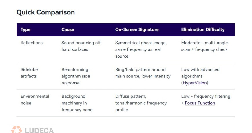
Reflections (Ghost Images)
Sound waves bounce off hard, smooth surfaces – metal walls, concrete floors, glass panels, polished pipes – just like light reflects off a mirror. When your acoustic camera picks up both the direct sound and the reflected sound, the reflected path appears as a second source at a location where nothing is actually producing noise.
- Typical scenario: You’re imaging a compressed air manifold mounted near a stainless steel wall. The display shows two hotspots – one on the manifold (real) and one on the wall behind it (ghost). The ghost image appears at roughly the same intensity and frequency as the real source.
- On-screen signature: Ghost images tend to appear at geometrically symmetrical positions relative to the reflecting surface. They share the same frequency spectrum as the real source and often appear at similar or slightly reduced intensity.

Sidelobe Artifacts
This is the most technically nuanced type. Beamforming algorithms work by mathematically “focusing” the microphone array on each point in the field of view. But just as a flashlight can’t produce a perfectly sharp beam edge, beamforming produces a main lobe (the focused area) surrounded by sidelobes – weaker response regions that can register false sources.
- Typical scenario: You’re imaging a single loud leak, but the display shows the main hotspot surrounded by a ring or pattern of secondary spots. These sidelobe artifacts are always clustered around the true source and become more pronounced when the source is loud relative to surrounding noise.
- On-screen signature: Sidelobes appear as a repeating pattern around the main source – often a ring, halo, or radial spoke pattern. Their intensity is always lower than the main lobe, and they maintain a fixed geometric relationship to the primary source regardless of scanning angle.
- Key factor: The number of microphone channels directly affects sidelobe levels. A 64-channel array produces more prominent sidelobes than a 128-channel array, which in turn produces more than a 200-channel array. Higher channel counts provide narrower main lobes and lower sidelobe floors. Advanced algorithms like CRYSOUND’s HyperVision processing further suppress sidelobes beyond what standard delay-and-sum beamforming achieves.
Environmental Noise Interference
Not every unwanted indication is a reflection or algorithm artifact. Sometimes, your acoustic camera is accurately detecting a real sound – just not the one you’re looking for. Background noise from HVAC systems, nearby machinery, overhead cranes, or even wind can register as apparent sources that get confused with your target.
- Typical scenario: During a compressed air leak survey in a manufacturing hall, you see multiple hotspots across a wide area. Some are genuine leaks. Others are background machinery noise that happens to fall within your selected frequency band.
- On-screen signature: Environmental noise sources typically have broader, more diffuse patterns than leaks (which appear as tight, focused hotspots). They also show different frequency characteristics – machinery noise tends to be narrower-band and harmonic, while leak noise is broadband and turbulent.
Thanks to CRYSOUND for sharing this educational blog! Click to continue reading, here’s a preview of what you’ll find:
- How to Identify False Positives: A 4-Step Process
- Techniques to Minimize False Positives
- Turning Artifacts into Allies: Using False Positives to Locate Sources
by Diana Pereda
Acoustic cameras turn invisible sound into visible images. This guide explains how they work, where they’re used, and how to choose the right one for your application.
What Is an Acoustic Camera?
An acoustic camera is a device that locates and visualizes sound sources in real time. It combines a microphone array – typically 64 to 200+ MEMS microphones arranged in a specific pattern – with a video camera and signal processing software. The result is a color-coded overlay on a live video feed, showing exactly where sound is coming from and how loud it is.
Think of it as a thermal camera, but for sound instead of heat. Where a thermal camera shows hot spots in red, an acoustic camera shows loud spots – pinpointing the exact location of a leak, a faulty bearing, or an electrical discharge that you can’t see with your eyes.
The technology was originally developed for aerospace and automotive NVH (Noise, Vibration, and Harshness) testing. Today, it has expanded into industrial maintenance, energy utilities, manufacturing quality control, and building acoustics.
How Does an Acoustic Camera Work?
The Microphone Array
At the core of every acoustic camera is a microphone array – a precisely arranged set of MEMS (Micro-Electro-Mechanical Systems) microphones. The number of microphones directly affects performance:
- 64 microphones: Entry-level, suitable for general-purpose sound source localization
- 128 microphones: Professional-grade, better resolution and dynamic range
- 200+ microphones: High-end, capable of detecting subtle sources in noisy environments
The spatial arrangement of these microphones matters as much as the count. Common configurations include circular, spiral (Fibonacci), and grid patterns. Each has trade-offs: spiral arrays offer good broadband performance, while grid arrays are better for near-field measurements.
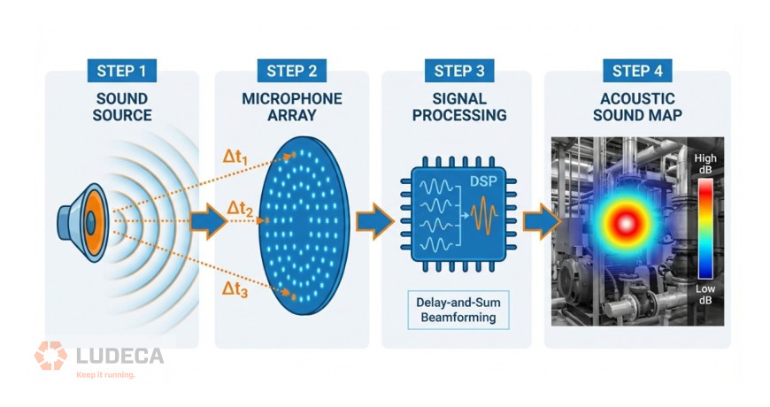
Beamforming: The Core Algorithm
The key technology behind acoustic cameras is beamforming – a signal processing technique that combines signals from multiple microphones to “focus” on specific locations in space.
Here’s a simplified explanation:
- A sound wave arrives at each microphone at slightly different times (because each microphone is at a different distance from the source)
- The software calculates the expected time delay for every possible source location in the field of view
- For each candidate location, it shifts and sums the microphone signals according to the calculated delays
- Locations where the shifted signals add up constructively are identified as sound sources
This process is repeated for every pixel in the image, producing a “sound map” that shows the spatial distribution of sound energy.
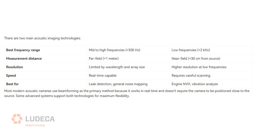
Beamforming vs. Acoustic Holography
The Role of the Video Camera
The microphone array generates a sound map; the video camera provides the visual reference. The software overlays the sound map onto the video feed as a color-coded heat map, allowing the user to instantly see which component, pipe, or connection is producing the sound.
High-end systems use depth cameras (such as Intel RealSense) to create 3D acoustic maps, enabling more accurate source localization on complex geometry.
Thanks to Crysound for sharing this educational blog! Click to continue reading, here’s a preview of what you’ll find:
- Frequency Range: Why It Matters
- Key Applications
- Types of Acoustic Cameras
- How to Choose the Right Acoustic Camera
- CRYSOUND Acoustic Camera Solutions
by Diana Pereda

Why Ultrasound Works Best for Low‑Speed Bearings
Utilizing standard vibration analysis techniques when analyzing data on slow speed (<50 rpm) machinery can be especially challenging. The reason for this is that rolling element defect amplitudes are extremely small and are usually hidden in the accelerometer’s noise floor and can’t be seen using conventional techniques. Ultrasound gets around this limitation because it has a high-frequency sensitivity that allows for the early detection of Stage 1 rolling element defects.
Detection Techniques and Practical Tips
Listen to the bearing
- Audible anomalies: Utilizing a headset, the technician can listen to the sound that’s being produced between the bearing’s internal components. If the technician hears knocking, clicking or crackling sounds, a Stage 1 defect is indicated.
- At extremely low speeds (<20 rpm) the sound amplitudes being measured on the bearing being monitored can be below 0 dBμV.
- Healthy slow speed bearings register sound amplitudes from –1dBμV up to 4dBμV. These values are highly dependent on the machine’s operating speed; however, when a defect is present, the values will increase and climb towards the 0 dBμV threshold.
Time‑Domain Analysis
- Time waveform (time-domain) analysis is an invaluable tool when analyzing slow speed bearings. Periodic impacting caused by defect frequencies (e.g., BPFO {Ball Pass Frequency Outer}) even at low speeds can be identified relatively easily by looking at data in the time domain.
- Sufficient data must be captured for analysis. For a shaft operating at 15 RPM approximately 15–20 seconds worth of data is needed to capture a full 3–4 revolutions of the shaft to be able identify defects associated with the bearing’s outer race, rolling element or inner race. However, in order to identify a defect associated with the bearing’s cage, a measurement of 10–12 revolutions of the shaft is required, and in some extremely slow speed machines this could take several minutes.
by Diana Pereda

When choosing an acoustic imaging camera, consider these five key factors to ensure optimal performance and reliability:
-
Microphone Array & Sensitivity
- A large number of microphones improves sound localization accuracy. Select a camera with no less than 200 microphones.
- A wide frequency range allows the detection of various issues, from air, steam, and gas leaks to electrical discharge. Make sure to pick a camera with a fast processor and at least 100 kHz bandwidth.
-
Detection Range & Precision
- Look for a camera with a long detection range to inspect hard-to-reach areas. The camera should be able to measure distances up to 200 meters (656 feet) with precision.
- The system should feature an acoustic imaging camera with greater than 12-megapixel resolution to enhance pinpoint accuracy for faster fault detection and more accurate diagnostics.
-
Real-Time Visualization & Dual Imaging
- Look for a system with a high-resolution LCD to provide real-time acoustic feedback.
- The system should also integrate thermal imaging to help detect heat-related issues alongside sound-based issues.
-
Data Analysis & Reporting Features
- Make sure the camera has onboard analytics to calculate leak volume and economic loss in real-time. This will help you justify the capital expense of the system as well as quantify the savings you can expect from performing the repairs.
- Choose a camera whose analytics give you the ability to identify electrical discharge types. This pinpoints potential safety problems and lets you plan the appropriate repair actions.
- Choose a camera that has advanced software and intuitive reporting.
-
Portability & Battery Life
- Opt for a lightweight, IP-rated, and ergonomic design suitable for industrial environments.
- Make sure your system offers a long battery life to ensure all-day operation without frequent recharging.
Choosing the right acoustic imaging camera, such as Ludeca’s CRY8128, can make a big difference in how efficiently and safely your team works. Keep these five factors in mind, and you’ll be well on your way to smarter, more reliable maintenance.
Simple Maintenance Practices That Drive Big Reliability Gains
by Ana Maria Delgado, CRL

Ultrasound is an especially good tool for detecting bearing problems on slow-speed machines. However, there are some common misconceptions about how this is accomplished. The rules behind the processing of the acquired signal are the same for ultrasound or vibration analysis.
A rolling element bearing’s Fundamental Train Frequency (FTF) or Cage Frequency is usually somewhere around 30% to 40% of the shaft turning frequency. This means that the shaft must rotate three or four revolutions before the cage has made one complete revolution. To correctly identify the bearing’s cage frequency, data should be collected during ten to twelve revolutions of the shaft, and in slow speed applications, this sometimes requires that the user set up the data collector properly to record for several minutes.
Analyzing vibration data collected on slow speed machines becomes difficult because they typically generate small amounts of centrifugal force. Accelerometers are designed to measure force and because of this detecting small bearing defect frequencies hidden in the noise floor becomes very challenging. Low levels of centrifugal force coupled with low level amplitudes coming from the bearing defect frequencies make identifying Stage 1 defects extremely difficult.
The good news is that ultrasonic sensors do not have this problem! Ultrasonic contact sensors measure the sound levels coming from the bearing and have been used successfully to detect bearing defects on machines operating as slowly as 1 rpm!
by Diana Pereda

Damage inside of a rolling element bearing begins with sub-surface fatigue and results in a detectable sound signal that occurs in the ultrasonic frequency range. Ultrasound can be used to detect these Stage 1 bearing defects which would not be visible looking at typical vibration spectrum. If you listen to the sound that is being produced from a bearing with a Stage 1 defect, it would sound relatively smooth and sound similar to a bearing that was in need of lubrication. The difference between the two is that after adding lubricant to the bearing with the Stage 1 defect, the amplitude of the sound would not decrease, whereas with a bearing requiring lubrication the sound level should reduce and return to baseline.
As the wear progresses and the sub-surface cracks become larger, eventually this damage enters Stage 2 and the cracks become a spall. The sound of each rolling element passing over a spall on the outer race of the bearing is easy to hear, and since the spacing of the rolling elements is consistent, the sound produced is consistent and repetitive.
Ultrasound is an especially good tool for detecting bearing problems on slow-speed machines. However, there are some common misconceptions about this and how it is done. Just because you are using ultrasound over a conventional vibration analysis setup does not change the rules of signal processing.
The same rules still apply using both.
The cage frequency or fundamental train frequency (FTF) for most rolling element bearings is usually somewhere around 30% – 40% of the turning shaft frequency. That means that the shaft must rotate three or four times before the cage has made one revolution. To be able to resolve the cage frequency at least ten to twelve revolutions of the shaft are required, and in slow speed applications this might require the user to collect data for several minutes in order to determine the health of the bearing’s cage.
Another consideration in monitoring slow speed machines is that because of their slow speeds they generate low amounts of centrifugal force and vibration sensors are designed to measure force. Thus, the low levels of centrifugal force coupled with low amplitude signals coming from the Stage 1 defect make it difficult for vibration sensors to easily identify Stage 1 bearing defects.
The ultrasonic sensor on the other hand doesn’t have this problem because it’s not designed to measure centrifugal force. The ultrasound sensor only measures the sound levels in within the bearing assembly and has been used successfully to detect bearing defects on machines operating as slowly as 1 rpm.
Download our 4 Stages Bearing Failures infographic for a basic reference guide to understanding the stages of bearing failures. Perfect to hang at your facility too!
by Diana Pereda

What is the proper technique for performing steam trap inspections? My short answer never changes. It involves two readings…one was taken a few feet upstream of the steam trap to ensure there is flow, and the other reading was taken immediately after the steam trap. If the steam trap is operating correctly, you will hear it cycle. Ultrasonically, this means the signal downstream of the steam trap should be silent, followed by intermittent increases in dBµV levels, indicating a discharge.
By listening to a steam trap cycle this way, ultrasound technicians can determine if the steam trap is cycling properly and functioning as it should. Technicians will also be able to determine any linkage issues the steam trap may be facing.
Over the years, I have found issues with this inspection method. The most glaring issue is that steam traps vary widely in cycle times. This leads to inconsistent and unpredictable inspection times. While this is more of a nuisance than anything else, it still makes inspectors think twice about performing inspections and predictive maintenance interventions on steam traps – especially when considering most steam traps can be replaced for a few hundred dollars.
What Do Unmaintained Steam Traps Cost You?
Is it a waste of time, money, and resources performing condition monitoring and implementing predictive maintenance interventions on an asset with such a low replacement cost?
No! It is not a waste of time, money, or resources. Your steam system and the steam traps that comprise them are designed to deliver clean steam from the boiler rooms to the intended point of use as efficiently as possible. And steam is not a cheap industrial resource to create.
The heat energy required to convert water to steam is measured in British Thermal Units. One BTU raises the temperature of one pound of water, by one degree Fahrenheit. This means when a pound of the steam condenses back to the water, one BTU was wasted.
Your steam system should minimize steam loss, maximize the transfer of heat, and remove condensable and non-condensable gasses that make your steam impure. When the assets that make up your steam system are ignored, your steam systems components degrade, your steam systems efficiency deteriorates, and eventually, your steam system won’t be able to deliver on its engineered purpose.
Failures in your steam system result in lost steam through leaks and lost steam when it condenses back to water vapor, and lesser quality steam reaches its intended point of use. Failures in your steam system also mean more greenhouse emissions as a result of having to produce more steam to compensate for losses. The bottom line, poorly maintained steam systems result in more losses than that just the price of replacing parts.
Safely Inspecting Steam Traps
Before going further, I would first like to point out that steam is a dangerous commodity. Maintenance personnel, factory workers, and condition monitoring technicians need to be aware that steam has both pressure and temperature, not to mention it’s also invisible. When you see what most people call “steam,” it’s actually just water vapor that has cooled down and condensed back to water – and it’s not overly dangerous.
On the other hand, invisible steam leaks are very hot, very dangerous, very high pressure, and very INVISIBLE. They can burn through clothes and melt human flesh. This is why I always strongly recommend technicians go out to monitor steam traps and wear the proper PPE. That means wearing long sleeves, gloves, eye protection, and any other articles of PPE that are mandated for that location of your facility.
Before I enter an area where there might be live steam leaks, I like to perform an airborne ultrasonic inspection of the area. The best tool for this is the SonaVu™ Acoustic Imaging Camera, as it not only locates steam leaks in your steam system but also visualizes any potential danger on screen.
After performing an airborne ultrasound inspection and confirming there are no dangerous steam leaks, I can proceed with my contact ultrasound inspection on the steam traps I intend to monitor.
Click here to continue reading the entire article, “Best Practices for Inspecting Steam Traps” and learn about the remaining three best practices so you can properly inspect steam traps!
Related Blog: What are SDT Ultrasound Solutions Four Condition Indicators?
by Diana Pereda

Obviously, getting leakage repaired after the detection effort is done is extremely challenging and sometimes frustrating in today’s economy. But, where many plants fail, others do extremely well in managing their leakage levels. The latter plants are the ones using best practices.
In conducting leak assessments four important steps come up when researching the practices of the best-performing industrial plants. These are:
- Baseline and monitor: The best plants keep track of their leaks with flow meters and are able to identify where they are at and how much they have saved each time they do their leakage assessments.
- Proper tools for the job: Top-performing plants have an excellent set of ultrasonic detection tools at their disposal, with available staff trained on the use of the devices. There is a wide range of available leak detectors out on the market, from basic small-budget units costing less than $500 to top-of-the-line units costing over $10,000. For compressed air leakage auditing, it is usually best to use simplified leak detectors of mid-range cost. Very complex detectors designed for other ultrasonic work are often so complex they defend themselves from use, therefore staff rarely want to place these into service.
- Detect, document, and fix: Best-practice plants have a simple set of procedures in place where leaks are detected and tagged with brightly colored identification. The leaks are all documented and recorded in a database with accompanying photographs so the location can be easily found again and the required parts for repair procured. Staff is all trained on the cost of leakage and the use of leakage detection equipment. The database will provide an ongoing record of the trouble locations and the financial savings, which is available for staff and management. In all cases, a successful program requires someone to take responsibility for the follow-up of the leakage repair.
- Verification: Excellent leakage reduction programs ensure the results of the leakage repair is captured by some sort of easy-to-use monitoring system, with real savings calculated. This can go a long way in proving to management the benefits of spending the staff time repairing the leaks. The monitoring systems can also serve as a catalyst to further efforts. If the plant leakage level is regularly monitored, and a significant change is detected, emergency detection and repair efforts can be initiated.
Click here to continue reading the entire article, “Protect Profits with Compressed Air Leakage Best Practices”, to learn more about compressed air leaks and how ultrasound can help!
Thank you Ron Marshall with Marshall Compressed Air Consulting for this informative article!
Related Blog: 7 Compelling Reasons to Tighten your Compressed Air System
by Diana Pereda
The following is a dialogue that Paul Klimuc with SDT Ultrasound Solutions had with his students during the fourth Live Online Level One Ultrasound Certification Course.
Question: Should Compressed Air Leak Inspections be Performed During Planned Outages?
I am often asked about compressed air leak inspections… how often should compressed air leak inspections be carried out, should they occur during planned outages or regular operation hours, should the whole plant be inspected at once or should it be broken up into smaller more manageable sections.
Here are my recommendations for carrying out a successful compressed air leak inspection:
- Safety
- Frequency of Inspection
- Knowledge of the Network
- Update Plans
- Plan the Inspection
- Choosing your Equipment
- Data management
- Celebrating Wins

1. Safety
Safety is everyone’s number one job. Which is why I open every one of my LOLO Courses with the Poll Question, which profession suffers more casualties every year in the United States: Maintenance Workers or Firefighters? The answer is surprising to some. Even when performing a task as straightforward and “safe” as performing a compressed air leak survey, it is important to wear the correct PPE, earplugs, safety glasses, etc. And always remain aware of your surroundings. Download our Find-and-Fix Leaks with Ultrasonic Imaging procedure to survey your systems and detect compressed air, gas, and steam leaks with ultrasonic imaging.

2. Frequency of Inspection
Leak inspections are not a one-and-done task. They must be performed periodically, and it’s best if they’re broken up by dividing the plant into smaller more manageable sections and performing surveys individually (More on that later).
According to the Department of Energy, compressed air systems that have been more than a year without inspection and maintenance are likely to lose upwards of 35% of their compressed air to leaks.
So, when is the best time to perform compressed air leak surveys and inspections? During planned outages and shutdowns? No.
Ultrasound can be used effectively in extremely loud environments. The background roar of a production facility doesn’t impede its ability to locate the hissing produced by compressed air leaks. Also, if assets aren’t in operation, automated valves that close when production is down would affect compressed air supply throughout the facility, rendering the results of an air leak survey inaccurate.

3. Knowledge of the Network
Knowing the network will improve the speed and efficiency of compressed air leak surveys, while also familiarizing the inspector with potential safety hazards.
The best way to get to know your compressed air network is to walk the inspection route prior. In a perfect world, you will be able to get your hands on schematics that illustrate piping locations, and the route the compressed air flows.
Before beginning your ultrasonic inspection, you should have an idea of what type of challenges you will face, and which sensors you will want to use during your inspection.
Click here to continue reading the entire article, “Best Practices for Performing a Compressed Air Leak Survey” to learn about Paul Klimuc’s recommendations for carrying out a successful compressed air leak inspection!
Related Blog: Ever wondered why we don’t find compressed air leaks? Here’s why!
by Diana Pereda
John Garrison is a SDT Level One Trained Ultrasound Inspector working as a Melt Shop Mechanical Technician in Alabama. This is part of his reliability journey as told by him.
As a mechanic in charge of a portion of the mill, safety and reliability are a must for myself, my company, and our customers. Giving our Operations group the best equipment and training possible are key to our success. For years we have outsourced the vibration, oil, and thermal analysis of our predictive maintenance program, and for years we have thought it was acceptable. But I can recall many occasions when components said to be good, turned out to be bad, or components said to be bad, turned out good. It was clear that our reliability program needed more.
I was approached by management and asked to lead an ultrasound campaign to improve our reliability program. The first thing we did was buy an SDT270 unit. When it arrived, I found myself staring at an expensive, little blue box which I had no clue what to do with. Shortly after I discovered SDT had a Live Online Level 1 Class starting soon, so I registered. I was pleased with all the additional on-demand webinars, lessons, and hours of learning from experienced reliability professionals that also came with the course.

I would recommend this course to anyone interested in becoming more familiar with ultrasound regardless of current skill set. There is something to be learned for all levels of ultrasound inspectors. While some classes make you feel like a prisoner voluntold to be there, not here. It is fun, engaging, and flourished with a plethora of useful knowledge and information. In the short 8 weeks of this class, I have found several failing components in our mill. I’ve been able to prevent unplanned downtime multiple times by planning to change the components on our time rather than running them to failure.
Click here to continue reading the entire article, “Stories From the Melt Shop” to learn about John Garrison’s reliability journey and how ultrasound can help!
Thank you SDT Ultrasound Solutions for sharing this testimonial and case study with us!
by Diana Pereda
The ability to perform inspections on sealed enclosures in order to identify areas that could leak under pressure or vacuum is easily accomplished by utilizing ultrasound.
When a component’s tightness integrity deteriorates, one or two things can happen. Internal process fluids or gasses can leak into the environment, or contaminants can get into the process which can sometimes be catastrophic.
Examples of this include:
- Inspection sealed storage tanks.
- Seals for vehicle around the passenger compartment.
- Identification of leaks in welded and fabricated tanks.
- Inspection of waterproof enclosures for equipment or switchgear
- Shipping container and hatch inspections for the Marine cargo industry.
- Inspection of bulkhead seal areas on ships where electrical cables pass from
- One sealed compartment of a ship to sealed compartment.
Watch our Tightness Testing with SonaVu Acoustic Imager video and learn how Ultrasound Imaging helps surveyors confirm the weather tightness of freight ships and eliminate spoiled cargo while ensuring the safety of crew members. Survey, detect and report leaks fast with our SonaVu™!
by Diana Pereda
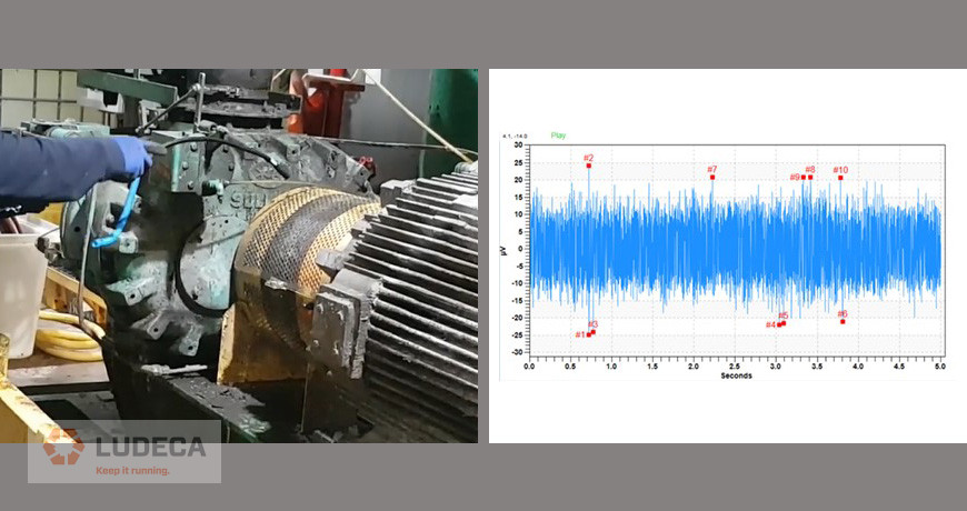
Using the SDT flexible airborne sensor, sweep the coupling area listening for clicking, crackling, and/or popping sounds. The sound coming from a good coupling should be a low constant noise without any clicking or popping sounds.
The data shown below was taken from a flexible style coupling in good condition. Notice the low amplitude scaling (+30/-30 uV) on the left side of the data graph. Also, the waveform is relatively flat, indicating that no impacting is occurring.
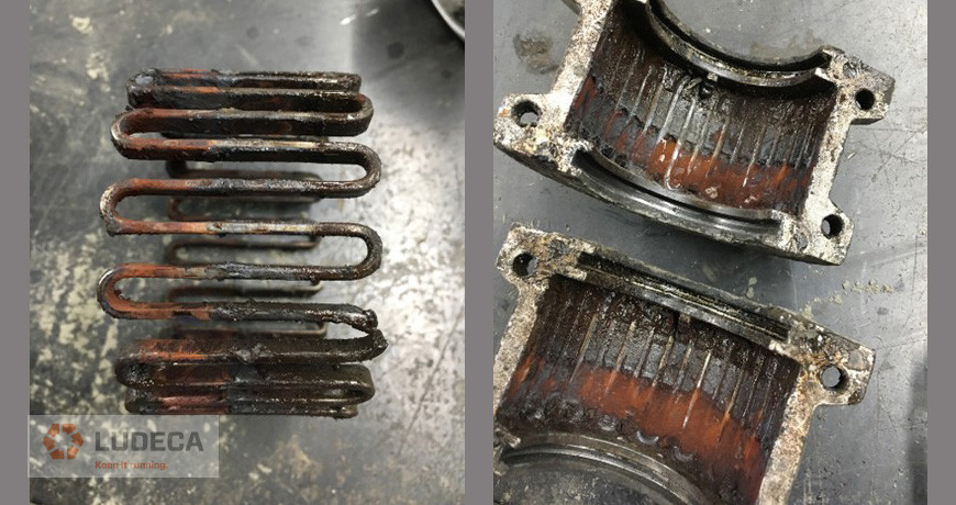
Contrast this with data shown below which was taken from a flexible grid-style coupling that lacked lubrication and as a result had caused damage to the coupling’s flexible grid.
Notice that the amplitude scale is now (+2000/-2000 uV) and impacting is apparent in the waveform data. In the spectrum, you can see an elevated turning speed peak with multiple harmonics indicating looseness and wear.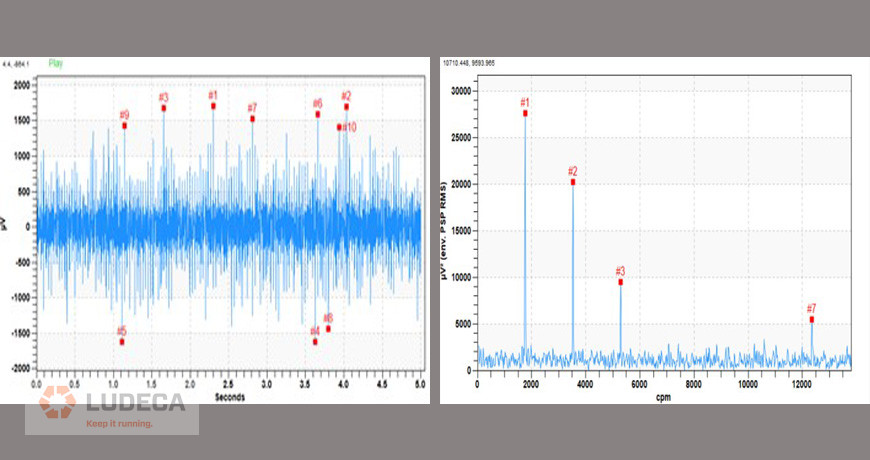
The images below show the condition of the flexible grid and the inside of the coupling housing after disassembly.
Download our Coupling Faults: Signs and Signals with Airborne Ultrasound infographic for a basic guide to coupling inspection using ultrasound technology.
Related Blog: Ultrasound and Alignment Meet at the Coupling to Reduce Failures
by Diana Pereda
Considering an Acoustic Imaging Camera? Read My Buying Tips First
Each year our condition monitoring world experiences innovation at some level, be it great or small. Even through a pandemic, leading tech companies continue to transform their solutions for the greater good of reliability. A recent example is the arrival of Acoustic Imaging Camera technology, also known as ultrasonic imagers.
Acoustic imaging cameras combine extremely sensitive multi-frequency sound sensors with digital imaging technology to provide ultrasound inspectors with a clear picture – or video – that illustrates precisely where an ultrasound source originates. By marrying our vision sense with our hearing sense, a more complete outcome is possible for certain airborne ultrasound inspections.

Now, mapping the origin of a sound to its source through imagery is an innovative breakthrough, but for someone who has followed the ultrasound market for more than thirty years, I am not surprised by these developments. Let us not forget history. Ultrasound has been with us for a long time. The notion that sounds existed outside the limited range of human hearing was first discovered in the late 1800s. Some 130 years on, Pierre Currie’s research with piezoelectrics remains as relevant today as it was when the first SONAR techniques provided ship captains with a solution for navigating deadly icebergs. Today, ultrasound offers improvements to our lives through medical, industrial, navigational, and cleaning applications.
Acoustic imaging technology is not particularly new. Sound mapping techniques have existed for a few years now, focused primarily on quality control applications. More recently, some clever manufacturers pushed forward with ways to utilize the technology for condition monitoring applications, primarily for energy waste reduction and electrical asset reliability.
Buyer Personas
When new technology first hits the market, predictable buying patterns emerge. Manufacturers love the early adopters; leading-edge consumers who are always first to own the latest and greatest gadgets the market has to offer. These mavens serve as a proving ground for new tech and often, their input helps steer the development for 2nd and 3rd product generations. Early adopters exist in sharp contrast to the “wait and see” crowd.
The wait-and-see crowd prefers to remain conservatively on the sidelines. They want assurance the technology will live up to its hype before opening their own wallets. If it proves to be a passing trend, they do not want to risk their money – and ego – buying something that might end up sitting on the shelf. If the technology does take hold they will still be waiting in line when the next release is ready, preferring that the early adopters do the testing for them. Eventually, when they do come aboard, their patience is rewarded by a product with most of the early problems ironed out.

For both the “early adopters” and “wait and see” users, buying tips from a trusted source helps relieve the stress associated with selecting their first ultrasound camera. After all, the investment is considerable and there may only be one chance to get it right. As someone who has lived his entire career inside the wonderful world of ultrasound, I am happy to share my insights about what you should look for in an acoustic imaging camera. This article identifies which features you should consider as “must-haves” and which ones are fluffy bits of window dressing, only there to distract buyers from less obvious deficiencies.
Buying Tip #1 – Do not buy a brand for the brand’s sake alone.

Innovations often come from the most unlikely origins, and when they do, they are honest and authentic; like the two Steve’s from Palo Alto who, in 1976, set out with a single goal to make computers personal and accessible to everyone. Had their mission been “to create the world’s first two trillion-dollar company” or “the world’s most iconic brand” they would not have succeeded beyond the confines of their parent’s garage.
Many of the ultrasonic imagers emerging today share similar humble beginnings. Born and nurtured by underfunded, tech-savvy start-ups, they eventually find their way to market by hitching themselves to well-established brands. Be mindful of this when shopping for your camera. The biggest brands may make the louder noise when it comes to trumpeting their marketing message; make sure the solutions they offer are equally capable of detecting the quietest noises in the loudest surroundings. At the end of the day, those are the ones you need to hear.
Buying Tip #2 – Take a peek behind the curtains.

When manufacturers develop new products, they know they must compete for the attention of the early adopters first. Some will dress up a product with features and functions that make it stand out but do not necessarily add top priority value. This approach can confuse buyers into choosing their camera based on fluffy features rather than performance. To avoid being duped, continually ask yourself why you want an ultrasonic imager in the first place. For my money, the emphasis should be placed on sensitivity and detectability. An acoustic imaging camera should be capable of detecting multiple types of defects in varying conditions. Do not allow yourself to be distracted by less relevant window-dressing features.
Buying Tip #3 – Buy an all-purpose camera.

Some acoustic imaging brands promote one camera model for finding compressed air leaks, and another for electrical assets. Really? Do we need two cameras to perform the same basic job? Steady now!
Using ultrasound to detect partial discharge in electrical assets and leaks in compressed air/vacuum systems has existed in tandem for five decades. The jobs were always performed perfectly using filtered sensors tuned in the range of 35-40kHz. This frequency choice has proven optimal for detection performance set against the contrast of loud, noisy, industrial factories. It takes into consideration the distance between source and sensor, the directionality of signal for fast pinpointing, and performance in environments characterized by elevated levels of audible background noise.
The laws of physics remain intact. The turbulent characteristics of these defects have not suddenly changed. They are as detectable today at 40kHz, as they were in the 1970s, 1980s, 1990s, 2000s, and beyond. There are no new technological discoveries or breakthroughs that warrant using a higher frequency for electrical discharges. In fact, higher frequency signals have shorter wavelengths, attenuate faster, and travel shorter distances, hampering their detectability over long expanses.
Click here to continue reading the entire article, “9 Buying Tips for Acoustic Imaging Cameras” by Allan Rienstra with SDT Ultrasound Solutions to learn about this exciting innovative technology.
by Diana Pereda

When it comes to condition-based monitoring, no matter how hard you try, you can never have 100% failure protection. At some point and on some level—even at the smallest levels—something is going to go wrong and your assets are going to fail. The best choice is to always plan for those sudden failures to minimize their damage in the end. The only way to ensure that is to have a very good detection strategy in place. Ultrasound helps greatly in achieving this milestone by helping you monitor the health of your entire facilities, giving you a much better proactive approach.
There are a lot of ultrasound devices that give you sound support for sensing high-frequency signals and understand their nature and characteristics. You can predict failures very easily, reduce energy costs because of unwanted downtime, and increase the productivity. But before, you go pick any random ultrasound device for your condition monitoring program, it is very important to know your goals and needs from that kind of program. You should involve every concerning department from planning and scheduling team to the technicians. They will provide you those small details and major insights to buy the right technology for your company.
The activities like inspection, leak detection, bearing condition monitoring, valve condition monitoring, and such take a lot of time. It is not possible to look for all the leak points and especially monitor every corner of your electrical and mechanical systems by relying only on visual inspection. This is where ultrasound saves a lot of time by monitoring change in friction and detecting any kind of turbulence way ahead of time to avoid any serious impacts on your machinery. This gives you enough time to plan for downtime and do maintenance in a scheduled way.
Any good ultrasound program always starts with a complete roadmap of your destination. You should always have an assessment strategy and planned goal alignment meeting in place. This also includes checking what kind of hardware and software will you need and what you have already in place. After you have bought an ultrasound device, make sure you check the facility and plan for on-site visits once in a while. Then you have to learn with time, document everything, have scorecards made, and start tracking the performance all the way. The results are not instant so there are some small wins and little ROI in the start but it gets better with time.
The major element that plays a huge is the cultural change here. You need to start recruiting skilled people, have experienced teams and consult other companies who have expertise in the ultrasound technology reliability-centered maintenance programs. They will guide you all the way if need be. Once you have knowledgeable people in your organization, make sure learning never stops because it makes the cultural change much easier with constant interaction among the staff. Once you have successfully implemented an ultrasound program and start reaping benefits from it, celebrate the victories.
Hear more from Allan Rienstra in this podcast by James Kovacevic to understand ultrasound and predict failures easily, reduce energy costs because of unwanted downtime, and increase the productivity.
by Diana Pereda
MAY 2020 – TRANSFORMER TECHNOLOGY

The term “Electrical Asset” casts a large net over an important class of systems. Whether it be substations, transmission and distribution lines, transformers, or motor circuit control cabinets, electrical assets play a key role in practically everything we do. Like most things we take them for granted until they fail to deliver their value. Then we scream.
Energy’s journey begins at the point of creation, can include storage, then transmission, distribution, and finally consumption. That journey is full of risk and the most significant risk contributor is partial discharge. Partial discharge happens when insulation material is compromised. One thing we know for certain is that once partial discharge begins, it will only get worse.
Partial discharge is more common than we would like to believe, even in new installations. Detecting these defects represents a serious challenge. Particularly at an early stage. There is no one perfect inspection technique, or technology, which can, on its own, detect and localize every defect, in every instance on every part of the electrical system.
Selecting the most appropriate method requires that the inspector understand the nature of the defect and the signs and signals available to be detected. The next logical step is to have the right technology available to pinpoint their location. Ultrasound is one technology that is mandatory for all electrical maintenance personnel. To not only reduce the risk of arc flash explosion but also enhance the overall reliability of system components.
When speaking about risk, health and safety should always take center stage. Safety aside, we must consider the risks from unreliable assets and loss of electrical equipment. They are both linked to downtime, costly legal exercises, and ultimately lost profit. Ultrasound is a solution that provides a reduced risk of all three in one go.

Ultrasound helps reduce the risk of arc flash exposure by detecting defects which, when left unattended, will lead to an arc flash event. I am not suggesting for one moment that we should not use PPE and other preventative measures. But I am yet to meet an arc flash suit which can detect an arc flash at its inception. So, the question is this: If an Arc Flash Suit is the last line of defense, then what is the first?
Some reliability minds seem obsessed with machines that rotate, while failure modes of non-rotating asset components seldom receive the routine surveillance they need. The pump and motor receive attention while the balance of the system is run-to-failure. Ultrasound testing could change this lackadaisical approach; especially considering its versatility, ease of use, and applicability to most hydraulic defects.
Click here to continue reading the entire article, “Ultrasound for Reliable Electrical Assets” by Allan Rienstra with SDT Ultrasound Solutions to learn about the common failure modes for electrical assets and how ultrasound can help.
by Diana Pereda
To resume our “The Rights of” blog post series which included The Rights of Precision Balancing and The Rights for Precision Shaft Alignment, I decided to give compressed air leak detection and repair a try with some basic rights when using PdM technologies like Airborne Ultrasound and Acoustic Imaging.

Here are my 14 rights to help you find those pesky and costly air leaks. Can you think of any others?
- Right safety procedures before you start your survey.
- Right leak management procedure to help you find-and-find leaks.
Download our Infographic Find-and-Fix Procedure to help environmental sustainability with reduced energy waste.
- Right pre-survey check of compressed air system layout/drawings.
- Right pre-survey gauge check (PSI)
- Right pre-survey inspection of pipe location, valves and fittings.
- Right leak detection instrument
Now days you can choose from an airborne ultrasound tool like our SDT ULTRAChecker all the way to an ultrasonic acoustic imaging camera like our new SDT Sonavu.
- Right leak location before you tag it.
- Right measured dBuV value in defect log.
- Right LOTO procedures before you start repair.
- Right leak location and severity report.
- Right leak elimination.
- Right re-measured dBuV value in work order.
- Right estimate of the cost impact of leaks.
- Right comprehensive reports to share your wins throughout your organization.

Download our SDT LEAKReporter App to help you document and quantify your energy savings $$$.
by Ana Maria Delgado, CRL
We previously discussed misaligned couplings and how to reduce failures when ultrasound and alignment meet in “Ultrasound and Alignment Meet at the Coupling to Reduce Failures.” In this follow-up blog, we will discuss how ultrasound and alignment come together to improve belt-driven performance.
Misalignment in belt-driven equipment is one of the leading causes of failures throughout the industry. It breaks down machines and often costs your company thousands upon thousands of dollars in repair expenses and unplanned downtime. Imagine if you could combine two technologies you may already be using to prevent some of these failures. Ultrasound and precision laser alignment will make your maintenance department ever more proactive than ever before.
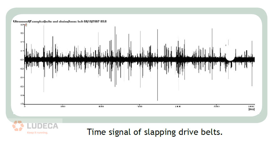
Belts can be too loose, too tight, or be running on misaligned pulleys. Loose belts will slap and produce a noise similar to whiplash. Tight belts and misaligned belts will generate additional friction which will again be audible ultrasonically. Figure 1 is a sample time signal of slapping belts.
An easy way to detect and prevent failures is to add your belt driven machines to your ultrasound routes. It will require a few extra measurements on each route and some trending. However, the benefits will far outweigh the costs. By being able to tell when a belt system needs to be aligned and properly tensioned before it breaks down, we can be more proactive and less reactive.
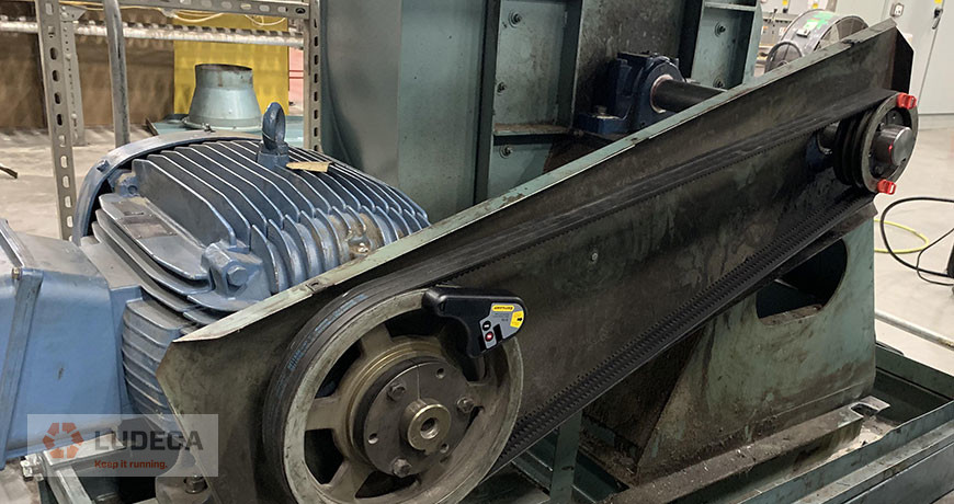
Once the imminent failure is being detected, we can address it with a realignment of the belt drive unit using our Easy-Laser XT190 pulley alignment system. It is easy to use and it will provide the user with a PDF report for documentation and accountability.
This blog was inspired by Uptime Magazine’s article, “There’s Something in the Air”, July 2009, pp. 48-53, written by Thomas J Murphy with SDT Ultrasound Solutions.
Download our 5-Step Sheave Pulley Alignment Procedure which provides a simple and effective procedure for sheave pulley alignment of belt-driven equipment.
by Diana Pereda