What is Machine Train Alignment?
Machine Train Alignment is a multi-coupling alignment where two or more consecutive machines can be adjusted.
For example, a 3-coupling train (4 machines), such as a Gas Turbine driving 3 Compressors.
NOTE: A 2-coupling (3 machine) train such as a Pump–Gearbox–Motor, where the Gearbox in the middle is determined to be NON-movable, is NOT a Machine Train; it could be treated as one but that is not the best option. It is best to treat this as two separate alignments using the Gearbox as the ‘Stationary Machine’. In one alignment, align the Pump to the Gear-Box, and in the other, align the Motor to the Gear-Box.
NOTE: Normally, most laser shaft alignment tools will use the first machine on one end of the train, say the left machine, as the Reference Machine, and after collecting the data at all couplings the alignment tool will combine all the misalignment values to calculate the required moves to align ALL the machines in the train to the original reference (alignment line), in most cases machine number ONE.
Is this the goal we are trying to achieve? NO! We are trying to align two machines next to each other. Then, what is the value of the machine train program? A TREMENDOUS VALUE, as it gives the aligner “the Overall Picture” of how all the machines sit with respect to the reference line and therefore also how they sit with respect to each other. Why do we need to know this? Because we need to avoid getting ‘Bolt Bound’ or ‘Base-Bound’.
We will use an Easy-Laser XT 770 Laser Shaft Alignment tool with data collected in a 4 machine train (3 coupling) for this blog. In a four-machine train, after reading the misalignment at each of the three couplings, we found the following Horizontal Misalignment values versus the entered Misalignment Targets that were desired. See Pictures 1 and 2 below.
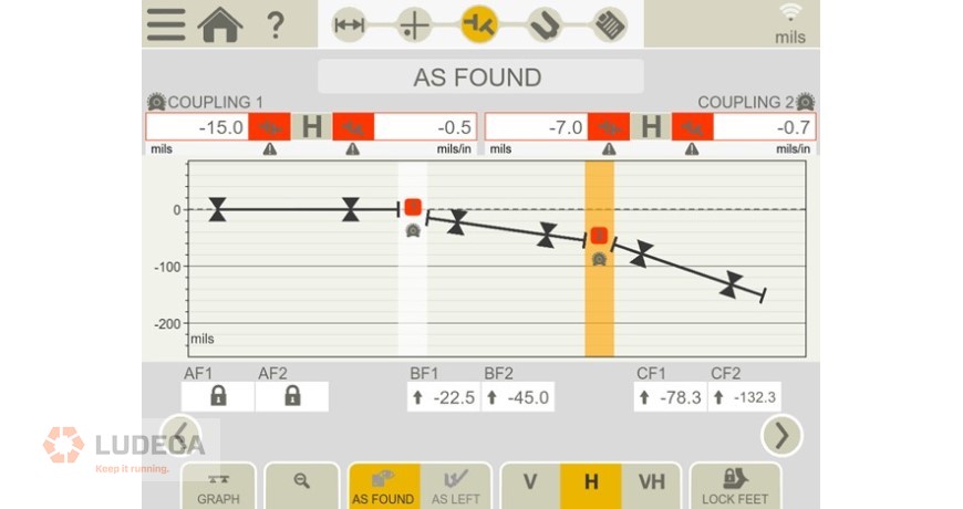
What we observe in Picture 1 is a laser alignment tool depicting the first TWO couplings (3 machines) in the THREE coupling train. We see that the first machine is the reference (Stationary Machine), we observe both the misalignment at couplings 1 and 2, and the required Horizontal Moves to align machine number TWO (BF1 and BF2 moves) and machine number 3 (CF1 and CF2 moves) to the reference machine number 1. We begin to see a big move at CF2, 132 mils (Thou). CF2 is the Compressor #2 Back Foot.
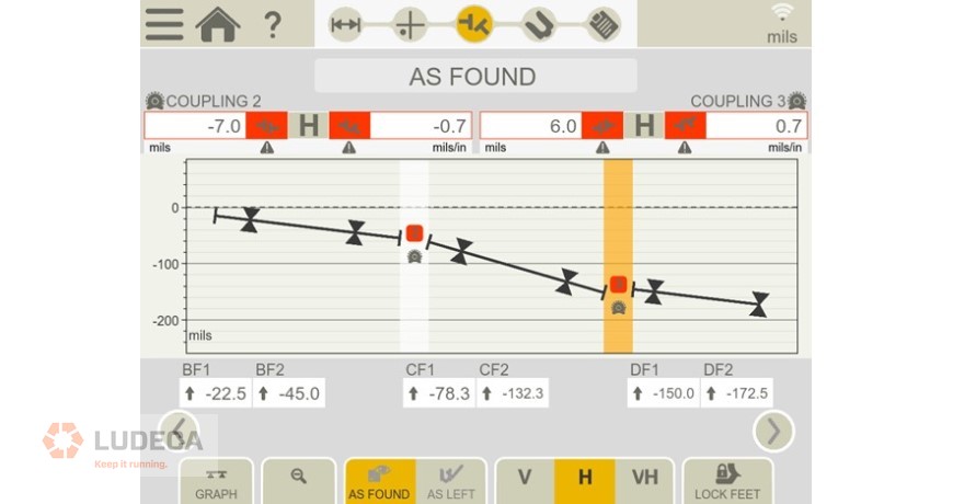
What we observe in Picture 2 is the misalignment at couplings 2 and 3 and the required corrections to bring all THREE machines to Machine ONE, the original reference (Alignment Line). See a possible problem now? Do you think we will be able to move DF2 172 mils (Thou)? DF2 is the Compressor 3 Back Foot.
In my next blog, we will then see how easily we can analyze and solve the apparent bad situation we are facing.
NOTE: Please realize that the pictures you saw are ‘GRAPHS TO SCALE’ of the misalignment. Observe the scale on the left side of the graphs.
Filed under:
Alignment by Diana Pereda