We welcome you to read the previous blog in this series, “What is Machine Train Alignment and How Important Is It? Part 2”
ANALYSIS 2: THE REFERENCE MACHINE IN THE TRAIN CANNOT BE MOVED
Now we have to face the situation of the big 172 mils moves at DF2, Compressor 3 back foot. For this, we are going to make use of the XT770 Adjustment Guide to predict what will be the minimum moves needed at Compressors 1, 2, and 3 to get the misalignment to excellent tolerances.
Here is a brief description of what is the Adjustment Guide and how it works:
It is Firmware utility built into the Easy-Laser XT770 alignment system to aid the aligner to predict what will be the minimum moves or shim changes required to align all the machines in the train to get the alignment at each coupling within tolerance when there are limitations to adjustment such as when Machine 1 cannot be moved in a 3-or more machine train. Let’s explore what can be done in our alignment.
As stated in Blog1 the calculated corrections at Machines 2, 3, and 4 are to bring the whole train to alignment to Machine 1. We also spoke on how valuable this information is.
Now that we know ‘the whole picture’ of the train and we know that Machine 1 cannot be moved, we can make ‘virtual moves’ and predict the minimum required moves at each pair of machine feet to get the alignment between consecutive machines to excellent tolerances. See examples in pictures 7, 8, 9, 10, 11, 12, and 13.
When we first invoke the Adjustment Guide we see a graph pictured below.
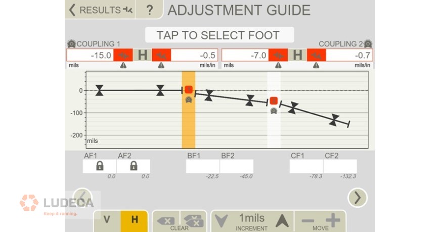
Allow me to describe what we are looking at in Picture 7. Several things:
- The actual misalignment at couplings 1 and 2.
- Machine 1 feet, AF1 and AF2 are ‘Locked’ because they cannot be moved.
- We see empty white rectangular boxes under BF1, BF2, CF1, and CF2.
- Underneath the white rectangles, we see the needed adjustments to make to bring machines 2 and 3 into alignment with Machine 1.
- We see the interval set up, set to 1 mils by default, and of course adjustable up to 125 mil increments every time you press the + or – icon. In other words, user-adjustable to save time.
- The left and right arrows allow the user to move down or up on the machine train.
Having said this, we used the arrows to ‘virtually move’ BF1 and BF2, see below.
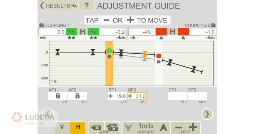
Picture 8 shows the final virtual adjustment on BF1 and BF2 to get Machine 2 to ‘Excellent’ alignment relative to Machine 1. Please note a couple of things:
- We needed to move machine 2 only 19 mils at BF1 and 31 mils at BF2 instead of 22.5 mils and 45 mils to get to excellent alignment. And more importantly…
- It allows us to leave the angularity of machine 2 with an angle such that machine 2 ‘points towards machine 3’, thus minimizing the moves at machine 3 to get it to perfect alignment with Machine 2.
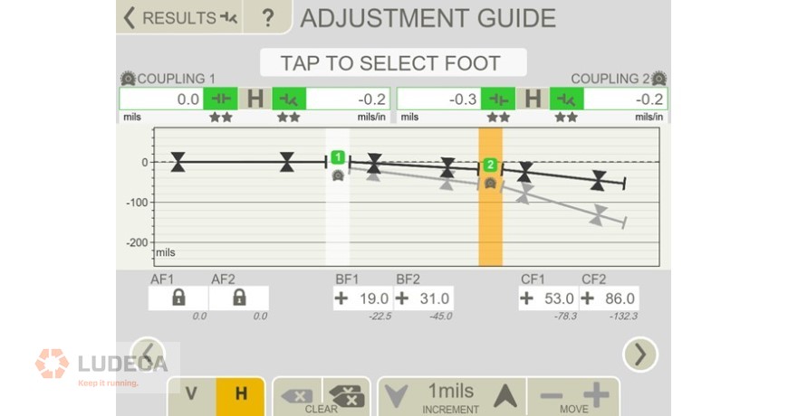
Picture 9 above shows the ‘virtual moves’ needed at CF1 and CF2 to get Machine 3 aligned to excellent tolerances with respect to Machine 2.
Please note that to achieve Excellent alignment the move at CF1 is only 53 mils instead of 78.3 mils and at CF2 it is 86 mils instead of 132.3 mils. Also note that we left Machine 3’s angularity in such a way that Machine 3 points towards Machine 4, thus minimizing the moves that will be required at Machine 4.
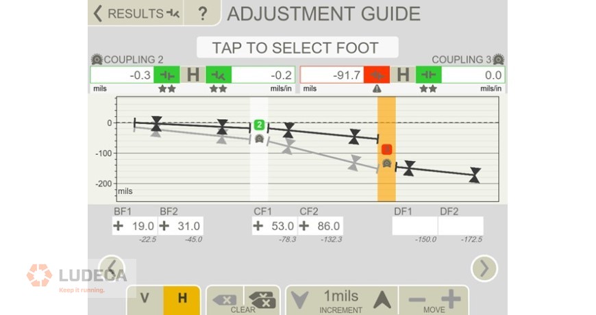
Picture 10 below shows the last 2 couplings and DF1 and DF2 with ‘empty’ values.
Underneath the empty rectangles that are waiting for the input of the virtual moves, we see the required move to bring Machine 4 (Compressor 3) into alignment with Machine 1, which are, DF1 150 mils and DF2 172.5 mils. However; what is needed, as pointed out before, is only to bring Machine 4 into alignment with Machine 3, not with machine 1. See Picture 10 below.
We continue the process as we did before making ‘Virtual Moves’ at DF1 and DF2 in any order until excellent alignment is achieved. See Picture 11 below.
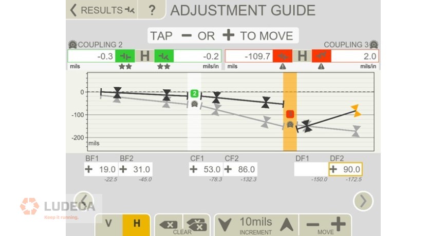
Picture 11 shows that we have ‘Virtually Moved’ DF2 90 mils.
We will proceed to move DF1 and DF2 in any order until we reach excellent alignment. Remember the ‘increment’ is adjustable, hence when getting close to alignment it can be lowered to 1 mil to make more precise moves.
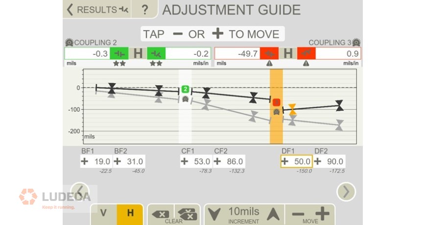
Picture 12 shows that we have moved DF1 50 mils and DF2 90 mils.
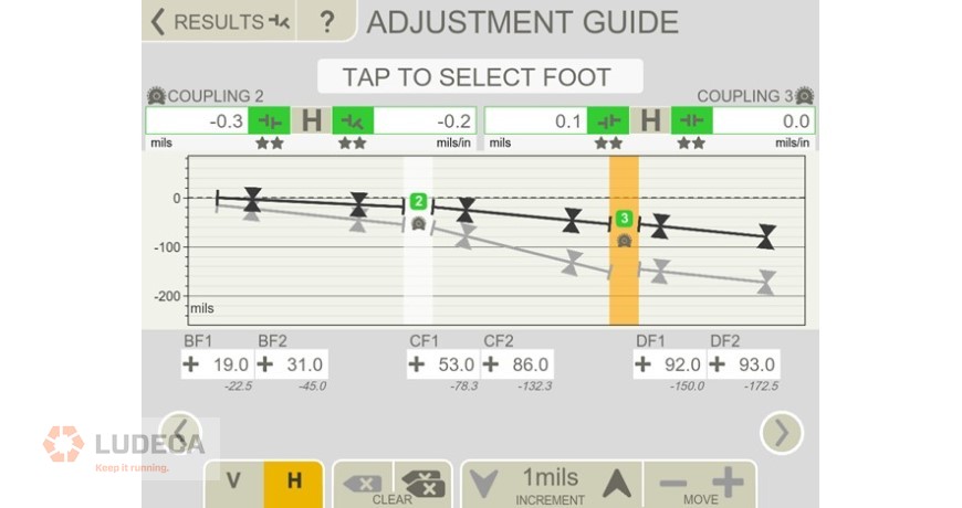
Picture 13 shows the moves required at DF1 to be only 92 mils instead of 150 mils and for DF2 only 93 mils instead of 172.5 mils to achieve alignment to tolerance.
As we can see, the Adjustment Guide utility is a tremendous aid that helps the aligner predict what is going to happen and most importantly find out if he or she will be able to obtain his or her goal.
Filed under:
Alignment by Diana Pereda