June 2011 • TPO Magazine
ACING IT IN OKLAHOMA
Strong skills, preventive maintenance and good planning lead to success at the Coffee Creek Treatment Plant in Edmond.
The Coffee Creek Wastewater Treatment plant in Edmond, Okla., has had near-perfect compliance for 38 years and has won several awards, most recently 2010 Large Wastewater Plant of the Year from the Oklahoma Water and Pollution Control Association (OWPCA).
It all has happened with a staff of five, despite rapid population growth, several upgrades, and various episodes with collection system inflow and infiltration. “When you have only five staff, you have to focus on working smarter, not harder,” says Fred Rice, water resources superintendent for the city. This means preventive maintenance, SCADA monitoring of critical alarms, and ongoing equipment and safety training.
It’s also a matter of teamwork. Kris Neifing, chief plant operator, hired in 2004, supervises two operators, a maintenance specialist, and a lab technician, and is also responsible for one lift station at the plant and nine lift stations located throughout the collection system.
Rice credits Neifing and his staff for the plant’s track record. “Kris has really pulled everyone together as a team,” he says. “All the credit for what we’ve achieved in the last six years is due to Kris and his staff. My role is like coaching a sports team. You can coach them, but the team executes the plays.”
Says Neifing, “What makes us successful is that everybody has different skills that collectively make us the best we can be. Some are better at maintenance while others prefer operations. We believe that no one knows how to do their jobs better than the ones who do it every day.”
Continuous improvement
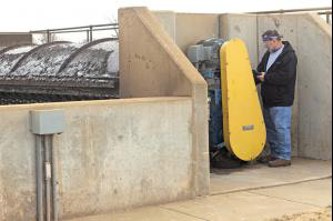
The plant’s compliance and safety record do not mean the staff is complacent. “We strive to continuously improve,” says Rice. “There is no process out there that can’t be improved, especially on the maintenance side.”
Rice and Neifing frequently attend the WEFTEC conference and other trade shows to check out the latest equipment. This has led to several innovations, such as vibration analysis and laser alignment equipment to help ensure that pumps and motors operate normally with the lowest possible maintenance. Rice and Neifing also read trade journals and network with others in the wastewater treatment business to glean ideas.
“The staff comes to us with ideas, like getting air compressors for maintenance, and suggesting better equipment or ways of doing things,” Neifing says. “We empower them to make suggestions, and we listen.” Adds Rice, “The city started a program based on the general concepts in the Good to Great book because we believe that organizations that excel are successful from the ground up. We give our employees responsibility and then hold them accountable.”
Read the entire article Acing it in Oklahoma
by Ana Maria Delgado, CRL
When craftsmen are given the task of laser alignment, quite a few assumptions are made. One very common assumption is that now that a laser system is being used, anyone can do an alignment. Another is that since a laser is being used, everything is alignable. Put a laser system on an unalignable machine and you will still have an unalignable machine, only with an expensive laser alignment system attached to it. A laser alignment system does NOT guarantee that a machine is alignable!!! (Actually, all machines are ultimately alignable, if only you throw enough time and resources at them- perhaps an entirely new base or foundation is needed, and/or redoing the entire piping. The question is, is it worth it in some cases? The point is, that just because you put a laser on a machine, that does not make it instantly alignable, vanishing all other problems.)
However, a laser alignment system, combined with a skilled and trained craftsman and a good alignment procedure, will greatly expedite alignments and help determine if a piece of equipment is alignable at all. The following is a tried and true procedure that will greatly expedite alignments.
Pre-alignment checks are critical in ensuring successful alignment. All surfaces should be clean and burr-free with metal-to-metal contact between the feet and shims, and the shims and base. Shim packs should be consolidated to three or four shims per foot. Jackscrews should be installed. A concentricity and runout check should also be done on the coupling and shaft. It is also a good practice to check the base for flatness.
The next step is to accomplish a rough alignment. Use whatever method that you prefer to get the machines reasonably close, or “eyeball” clean. A straightedge will work on some couplings in short-coupled machines. On machines with spacer couplings, the laser and a tape measure can be used very effectively. The purpose of this step is to remove gross misalignment and ensure that the laser and detector are in line enough to take readings. (Note that the best laser systems offer range extension so even rough alignment can easily be done with the laser.)
After your rough alignment has been accomplished, a rough soft foot check is in order. Eliminate any obvious rocking and fill any obvious gaps. This should be done with all hold-down bolts loose. Now it is time to use your laser alignment system. Make sure that all required dimensions are entered accurately and that initial alignment measurements are repeatable. Assuming you still have a rough alignment, a final soft foot check is in order.
Follow your laser system’s recommendations for this. The ROTALIGN® ULTRA even features a comprehensive soft foot wizard that guides you through the entire process, diagnoses the condition, and suggests a solution. After any corrections are made, retighten all hold-down bolts, then recheck each foot individually with all the others tight.
We recommend a tolerance of 2.0 mils or less. Now for the final alignment: The first correction that should be made is getting the vertical plane in tolerance. When making shim corrections, monitor the horizontal plane to make sure your machine does not move laterally too much. Once you are satisfied the vertical alignment is in tolerance, proceed to final horizontal corrections. Leave the hold-down bolts snug (not tight). They do not need to be all the way loose to make effective horizontal moves. This is where good jackscrews become invaluable, Try to avoid hitting machines with hammers. When the machine is within tolerance alignment is complete. Save the alignment file for documentation and future reference.
Many years of involvement with machinery alignment reveal that this is the best and fastest procedure for precision alignment. Each step is necessary and important in accomplishing the next step. Take your time and be diligent and you will succeed in your alignment.
by Ana Maria Delgado, CRL
May 2011 • MAINTENANCE TECHNOLOGY
Cardan Shaft Alignment: These applications aren’t as straightforward as others. Their special considerations call for special tools and approaches.
A Cardan shaft is, in the simplest terms, a spacer shaft with a universal joint coupling on each end. (Its name comes from a 16th-century Italian mathematician, Girolamo Cardano.) This type of arrangement allows power to be transferred between two machines that are offset from each other.
Widely used in industry, Cardan shafts have proven practical in applications where space is limited—as well as in situations where an element in the machine train (e.g. paper roll) may need to be actuated (dynamically positioned) to an alternate position when the machines are not running. The universal joint allows for limited movement without uncoupling. To ensure sufficient lubrication circulation, which in turn prevents the universal joints from seizing, Cardan shafts are normally installed with an angle from 4 to 6 degrees at the universal joints. Experience, though, has shown that the angle between the shafts of the driver and driven unit should be kept to a minimum, preferably less than 4.36 mrads (0.25 degrees). Ideally, the angles between the driver and driven shafts and the Cardan shaft, shown as ?1 and ?2 in Fig. 1, would be equal. Geometrically, this would equate to zero angularity existing between the driver and driven unit: In other words, the shafts of the driver and the driven machine would be parallel to each other.
Read the entire article Cardan Shaft Alignment featuring the ROTALIGN ULTRA laser alignment tool suited for cardan-shaft applications.
by Ana Maria Delgado, CRL
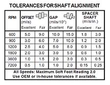 Some coupling manufacturers will sell couplings claiming that the coupling can take shaft misalignment. While this is true for most flexible couplings, it can be easily misinterpreted. Flexible couplings are designed to withstand, without damage, some shaft misalignment. Sometimes it is perceived that, since the coupling can take the misalignment, the machines can run under this condition without any consequences. When running machinery with significant shaft misalignment, bearing and seal life may decrease immensely, and other damage results. Therefore, for longer machinery life, it is always recommended to have equipment laser aligned to standard industry tolerances for shaft alignment, and not to the looser alignment tolerances allowed by the coupling itself.
Learn about Shaft Alignment Tools with Built-in Tolerances.
by Adam Stredel CRL

As the Project Manager for the Millwright Competition and a member of the 2011 ABC Craft Championship Committee, I want to thank you and your company for your support for the Millwright competition.
Even though I have never used that particular laser, it was very easy to use and only took about five minutes to become very comfortable with it. None of the competitors had used the SHAFTALIGN® prior to the competition, which was great. It only took about twenty minutes to show them how it operated, including thermal growth, soft foot, and static feet selection. Even though the competition required an 1800 rpm alignment with thermal growth, one of the competitors did a 7200 rpm alignment within the time limitation, which would never have been achievable with dial indicators.
I am proud to say that with your help and equipment this competition has finally evolved into a modern competition. Your alignment equipment is easy to install, easy to use, and accurate. It is the best alignment equipment that I have ever seen.
Again thank you for your support.
Ed LePage
Mechanical Craft Training Coordinator
CIANBRO Institute
Congratulations to Joseph Ducharme, the first-place winner.
by Ana Maria Delgado, CRL
March 2011 • IMPO MAGAZINE, iPurchase Supplement
As the American economy recovers, how aware, or active, are manufacturers concerning predictive maintenance?
Most manufacturers never lost the desire to increase their overall reliability and predictive maintenance efforts during the recent economic slowdown. Some companies did postpone purchases of predictive maintenance-related products. However, a lot of companies realize that an investment in predictive maintenance technologies is a viable means to decrease overall maintenance expenses, so they do it the right way. A lot of manufacturers, as a result of this understanding, continued to invest in predictive maintenance-related technologies during the recent economic slowdown. This allowed them to reduce overall maintenance costs and place their company in a more competitive position once the economy recovers. Interest in these products is higher this year as companies continue to invest in vibration- and alignment-related products to reduce their costs. increase competitive advantages, and manufacture equipment reliability.
Read the entire interview Q&A Roundtable from iPurchase, a supplement from IMPO Magazine including:
Are there any interesting trends occurring in the maintenance market?
Why do you think laser alignment is important to a manufacturer’s maintenance strategy?
How would you recommend a manufacturer approach the creation of a more robust maintenance plan?
by Trent Phillips
WaterWorld Magazine • February 2011
A Florida water treatment plant recently discovered that having full-flex (double engagement) gear couplings at either end of a spacer shaft connecting a Lufkin gearbox to a 13, 000 GPM Worthington water pump caused self-exacerbating vibration that eventually destroyed the gearbox twice within 3 months, requiring a full rebuild each time. After the second rebuild and re-installation, LUDECA was called in to monitor positional changes between the stopped and running conditions of the entire diesel engine-driven machine train with its PERMALIGN® system to derive true target specifications for the “cold” condition. Thereafter, a laser re-alignment to exact tolerances would be performed to the new targets…
Read the entire case study and view photos
by Alan Luedeking CRL CMRP
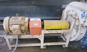
Problem: Exhaust fans
The exhaust fans at two of our process buildings kept having the same common faults (failed bearings, failed motors, and running hot.). We spent over $4, 400.00 on one fan from 2008 to 2010 and over $5, 600.00 on the other fan on parts alone.
Solution: Purchased an OPTALIGN® SMART EX laser alignment system
In July 2010, we received our new OPTALIGN SMART EX and had LUDECA come in and give us an introduction introductory training course. After a few trials on using the laser alignment tool on a motor and pump that we set up in the shop, we were ready to take it out in the field. We went and set the tool up on our two exhaust fans and found out there were way out of alignment. After a few tries, we had smiley faces on both machines in the horizontal and vertical directions. Since the alignment, we haven’t had any more problems with either fan. The OPTALIGN SMART EX is very user-friendly and well worth the money.
Now we have incorporated the OPTALIGN SMART into to our PM program to check the alignment on all rotating equipment as they come up for a PM. In the last few months we have been using it, we are getting good feedback from the maintenance department on how easy it is to use and how much time is saved, instead of doing it the old way (dial indicators). —Bryan Brown, PM Technician with MARTEK Biosciences in Kingstree, SC.
by Ana Maria Delgado, CRL
- Functionality: Do the Predictive Maintenance (PdM) tools you are considering have the ability to make all the measurements required by your physical asset management strategy? Are displays easy to see and interpret? Are the tools easy to learn and easy to use? Learn about our PdM tools. For Software, can it interface with your CMMS system? Can you import data from other systems such as oil data? Learn about our OMNITREND software.
- Durability: Will the tools hold up to your plant’s environment? Are they rugged enough for multiple users? IP ratings such as water–, dust– and shockproof are very important when dealing with industrial tools.
- Service: Will your vendor be available to answer questions or address problems should they arise? What is the vendor’s reputation for customer service? If you have a problem with a tool how soon can you expect a “loaner” until yours is repaired? Are the tools repaired and/or calibrated locally? Learn about LUDECA Repair and Calibration.
- Training: What are the training costs associated with learning how to use the tools? Is training included with the purchase? What training resources are available? Learn about LUDECA Training.
- Support: What level of support do you need? Does the vendor have a call-in tech support center, is it free or paid? Will the yearly costs of maintenance agreements make the tools considerably more expensive than competitors’ tools having similar capabilities? Do they offer free updates? Learn about LUDECA Technical Support.
by Bill Hillman CMRP
Pumps & Systems • January 2011
Aligning an electric motor coupled to a large air blower required multiple measurements.
Around 18 years ago, a client needed assistance aligning an electric motor (more than 1, 000 horsepower) coupled to a large air blower. This was a critical piece of equipment that was routinely shut down for preventive maintenance at regular intervals to ensure trouble-free operation. The mechanical contractor used for this alignment was reputable, and the customer had used him several times in the past for this task with satisfactory results.
Vibration Problems
Upon startup, vibration levels were so high that the package tripped and shut down before reaching full rpm, preventing any meaningful collection of vibration data to help identify the problem. This continued for two days. Convinced that the problem was alignment-related, the contractor made multiple corrections with the same results. Every time the package was started, vibration levels were high, and the package shut down before reaching full rpm.
Laser Shaft Alignment Assessment
The client requested that a shaft laser alignment system be used to ensure correct alignment. The motor and the blower were uncoupled, and all the hold-down bolts were at spec. Initial readings were taken. Remember, this was more than 18 years ago, so the alignment system was a much less sophisticated system than those available today.
Read the entire article Measure Twice, Cut Once!
by Dennis Onken
Machinery Lubrication, September • October 2010
In his book “Machinery Vibration: Alignment”, noted author and expert on precision alignment Victor Wowk illustrates the relationship between misalignment and loss of machine life. Of course, some equipment is more or less tolerant to misalignment depending on bearing type and coupling type. Likewise, the effects of misalignment are magnified as a function of speed.
Read the entire article Shaft Alignment has a Bearing on Lubrication Excellence
by Ana Maria Delgado, CRL
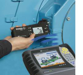 The ROTALIGN® ULTRA VIBRATION ACCEPTANCE CHECK works in combination with the VIBTOOL® vibration meter to measure vibration levels according to ISO 10816-3 international standards. The RMS velocity value is wirelessly transferred and stored back onto the ROTALIGN ULTRA computer where the result is instantly evaluated against the machine classification threshold. This fulfills the recommendation of the acceptance check after installation of rotating machinery or any alignment job, ensuring that machines run without restrictions. The VIBTOOL vibration meter can measure the following parameters: Vibration Severity, Bearing Condition, Temperature, RPM, and Pump Cavitation. More information about the new ROTALIGN ULTRA VIBRATION ACCEPTANCE CHECK
by Ana Maria Delgado, CRL
POWER-GEN Worldwide, September 2010
The alignment of turbine-generator sets poses unique challenges that only the best laser shaft alignment systems can overcome. Not the least of these is the difficulty of turning the shafts (either coupled or uncoupled) and the methods employed in turning them. The intent of this article is to present a few of these challenges and the solutions to them.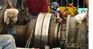
Shaft Rotation
Since a turbine-generator train cannot be readily rotated by hand (unlike most other smaller machine sets), external “helper” forces must be enlisted, such as an overhead crane with a sling around the shaft or coupling. As the crane applies rotational force it also lifts the shafts in the bearings a little, changing their relative alignment and true position in the bearings. This makes using the Continuous Sweep measure mode impractical since you do not want to corrupt the validity of the alignment data you are collecting as you rotate the shafts. The same concerns also apply to other methods, such as the chain fall and pin method…
Read the entire article Turbine-Generator Alignment featuring the ROTALIGN ULTRA alignment system.
by Ana Maria Delgado, CRL
Reliable Plant, August 2010
Traditionally, plumbness measurements on a vertical hydro-turbine/generator shaft involved stringing a series of wires along the length of the shaft, attaching a weight to the end of the wires, and then measuring the space from the wire to the shaft using an electronic micrometer. Although this method was inexpensive and has been used for many years, it did require access to a long length of the shaft to achieve an accurate resolution. Also, measurements involve physically measuring the distance between the wire and the shaft at various elevations on the shaft, increasing the amount of time and personnel requirement for the measurement. Ludeca presents its experience with a laser-based system that replaces the time-consuming wire method. Measurements now can be performed in a fraction of the time it would otherwise take with the wire measurement method. Ludeca’s measurement system, known as the PERMAPLUMB, uses a self-adjusting mechanical mirror, always plumb to earth, that reflects a Class 1 laser beam into a detector. It requires only 14 inches of axial space along the shaft.
The mirror and transducer are attached by a bracket that uses magnets on the turbine shaft. From a single 270-degree shaft rotation, the system calculates and displays angularity and corrective moves and provides a statistical quality measurement of the data. A “move” function allows monitoring of corrections as they are being made. The resolution is better than 0.00002 inches per foot, which is more accurate than required by NEMA. Adjacent turbines also can continue to operate since the system is insensitive to vibration.
Read our article: How to achieve vertical shaft plumbness using laser alignment
by Daus Studenberg CRL
July 2010 · IMPO Magazine
“You must be the change you wish to see in the world.” — Mahatma Gandhi
Investing in more efficient process machinery makes good business sense and will help to ensure reduced costs plus a greener plant. However, not all plants can afford to replace their present equipment with newer, more efficient machines. What steps can these plants take to “green up” their business and operate more efficiently? Most plants can vastly improve machine reliability, efficiency, and reduce raw materials conversion costs by simply making improvements in their present machinery. This can be done through precision maintenance practices and defect elimination. A good PdM (predictive maintenance) process will help to achieve these goals.
Read the entire article: Save Some Green: Green Up Your Machines
by Ana Maria Delgado, CRL
Problem: Our boiler feed water pump running on steam turbine kept failing numerous mechanical seals since 2006, and gave us very poor reliability. Due to the unreliable nature of the steam turbine, we had to keep running our electric boiler feed water pump as a primary pump. This cost us $$$ in terms of energy usage, as we were not able to use steam generated by our boiler to power the steam turbine pump.
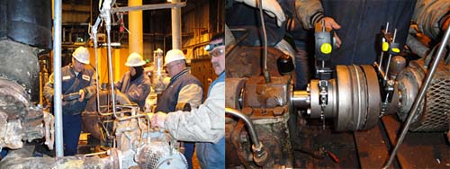
Solution: In February 2010, we ordered a new rotating assembly for the steam turbine pump and installed it. We also purchased a new laser shaft alignment system “OPTALIGN SMART®”. We had stopped laser aligning our equipment for the last couple of years due to the old laser alignment system not being calibrated and not being very user-friendly. After seeing a hands-on demonstration of the OPTALIGN SMART, our skilled trade group was convinced that we needed this new user-friendly system for laser shaft alignments. Upon laser aligning the steam turbine, we found that we were way off in both Horizontal and Vertical alignment. Using the OPTALIGN SMART, we were able to achieve a much better alignment than we ever did. We did not get the “smiley” faces on our alignment, but that was due to having a tremendous amount of pipe strain, poor base condition, and being bolt-bound. However, our steam turbine has been running smoothly without any issues since February 2010.
According to some operators, the steam turbine has never run this quiet and long in the past. We have started using the OPTALIGN SMART laser shaft alignment tool on all our rotating equipment, and have already seen some really good results and overall cost savings in maintenance labor and materials. —Nihal Raval, Maintenance/Reliability Engineer with SOLUTIA
by Ana Maria Delgado, CRL
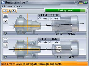
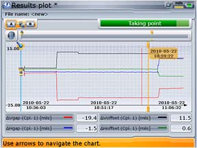
The biggest contribution one can make to lower the operating costs of rotating systems is to align them correctly using the real coupling target values. Target values recommended by manufacturers do not always reflect the real machine centerline movements due to thermal growth, pipe strain, and dynamic factors. The new ROTALIGN® ULTRA Live Trend, a short-term continuous monitoring application, helps to exactly determine the relative positional changes between coupled machines during start-up or shut-down. By applying these values, the machines are precisely aligned to reflect normal operating conditions. In addition, Live Trend allows you to establish a trend of the events that influenced such positional changes. With Live Trend, you can also monitor pipe growth and any other machine components over time.
- Lower energy costs through reduced power consumption
- Increased mechanical life of bearings, seals, shafts, and couplings
- Reduced bearing and coupling temperatures
- Minimized breaking or cracking of shafts
- Reduced vibration
- Reduced machine damage
Reliability starts with precision shaft alignment!
by Ana Maria Delgado, CRL
The following situation occurred at a Municipal Power Plant. During a planned outage, the on-site team was utilizing a Rotalign® Pro with Boralign® to assess the position of the bearing bores after the removal of the rotor on an Allis Chalmers power generation steam turbine. The results were varying far more than normal and the customer wanted to understand why. I was called in to make sure there were no errors in the use of the Boralign system. The tool was being used properly and there were no problems with the tooling. The customer had already set the unit up on a surface plate and established that there was no appreciable drift with the tool. I suspected excessive vibration, so I used my Vibscanner® to measure overall vibration in displacement. No significant level of vibration could be detected; certainly not enough energy to cause the level of non-repeatability they had been observing in the readings. I thought if the movement of the lower shells had a very low frequency that was too slow to measure utilizing traditional vibration sensors and methods, I might be able to measure it with the Rotalign Pro Straightness program. Both the laser and receiver were mounted on standard magnetic dial stands with brackets that are part of the Straightness hardware set. A series of points were established on the lower shells to measure between, both along the rotational axis and from side to side. Setting the Rotalign Pro Straightness program to the shortest sample time and observing the X-axis values over a 2 to 4-minute period, I was actually able to see a very slow movement between various points on the lower shells. While some areas of the lower shells were reasonably stable, there was movement between some points that was as much as .024”, but at a very low CPM. While this process was somewhat like ODS, there was no real-time phase data, so I could not tell how the various points were moving relative to each other. It was still very helpful to the rotating engineer to understand how much the various areas were moving. Better yet, with a fairly simple program and only 6 hours invested in collecting the data, the rotating engineer had a good idea of the magnitude of the problem.
by Keith Van Hentenryck
July 2010 · Maintenance Technology Magazine
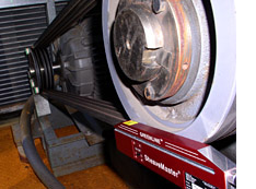
Properly maintained V-belt drives can be up to 97% efficient. Poorly operating belt drives can waste as much as 10% additional input power. Let’s consider a scenario that ignores motor losses and only considers losses in the belt drive. With electricity costs of seven cents per kWh, a rotor operating three shifts per day, five days per week, and requiring 50 horsepower from a belt-drive would consume over $16, 000 of power annually. An additional drop in efficiency of only 5% would result in increased costs of over $800 per year. In some industries, such belt drives may comprise more than 50% of the total drive population. This example clearly shows that big savings can be realized by properly maintaining them.
Read the entire article: Maintaining Belt Drives For Maximum Savings
by Bill Hillman CMRP
I recently completed a shaft alignment between a Solar Gas Turbine and a Gearbox on an offshore oil platform. The unique features only present on the ROTALIGN® ULTRA were key to this success. The repeatability we obtained was outstanding, less than 1 thou per measurement. Here are the reasons for our success:
1. We used the “Multipoint” measurement mode to perform an uncoupled measurement. Although the “Continuous Sweep” mode is a very fast and accurate measurement mode that takes thousands of points in a continuous sweep (one of our favorites), sometimes you don’t want to turn the shaft and measure at the same time. This was the case on this gas turbine, which was unique in that the shaft could change its radial position while you turned it. “Multipoint mode” takes not just 3 positions, but many measurement positions for superior accuracy. 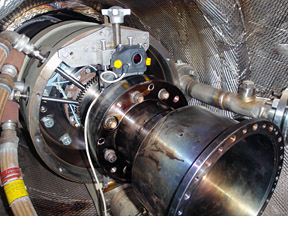
2. The Standard Deviation function let us know we were taking accurate readings during the measurement. Standard Deviation was invaluable because sometimes we would find the shaft would not center itself after turning. Standard Deviation would reveal this while taking measurements, thus saving time and ensuring our accuracy.
3. “Multipoint” mode allowed us to adjust the number of measurement points taken per measurement position, up to 2048 points to be exact! Vibration is a fact of life out in the field. With this feature, vibration is negated. In fact, we only needed 128 points per measurement position and that took less than one second per measurement position.
by Daus Studenberg CRL

