March 2021 – Pumps & systems
In olden times, when hard work beyond the ability of a few humans was needed, a horse or a team of oxen was the solution. Even greater power requirements were fulfilled by wind or watermills. This form of driving machinery lasted for centuries and the mechanical components involved required little in the way of alignment, beyond rudimentary good fits. When self-powered machinery was invented in the early 19th century in the form of James Watt’s steam engine, the pace of industrialization began to quicken. With this revolutionary power source, the volume of manufacturing increased rapidly and a greater demand for water and other fluids in industrial processes was created.
While early machinery often transmitted power via gear drives and flat leather belt drives, it did not take long for engineers to realize that directly coupling the driver to the driven machine would result in improved efficiency of power transmission with all the savings entailed therein. It is only with the invention of modern multiple V-belt drives with negligible stretching and slippage that the efficiency of belt-driven systems again rose to compete effectively with direct-drive systems.
In early days, speeds of rotation were slow and alignment of both belt-driven and directly coupled machines was traditionally accomplished by eyeing it, using a straightedge and feeler gauges. Good machining of surfaces and great care was usually all that was needed to obtain a satisfactory result. This modus operandi persisted through the 1940s. By the end of World War II, the United States was in a commercial position that favored industrial production: almost all of the world wanted manufactured goods, and the U.S. was a principal source for them. If someone wanted a car, a TV, or a sheet of stainless steel, it was likely made in the U.S. Global competition did not exist to nearly the extent that it does today, so cost-consciousness was not what it is today. Resources were plentiful, environmental regulation minimal, and craftsmanship excellent. Plants could afford to install standby machines for all critical processes and concrete foundations were poured a little deeper. People designed machines using slide rules. Today, computers trained to shave away every unnecessary ounce of metal do the designing.
In the 1930s, the average speed of rotation of an electric motor was 900 or 1,200 rotations per minute (rpm). Back then, the straightedge was king. Pumps had stuffing boxes, and when they sprang a leak, the mechanic simply tightened the packing glands to compress the braided cotton and asbestos packing rope until the leak went away. Often, the shaft was later found to be scored from the pressure of overtightening. As industrial production flourished and a wide range of new products were introduced, harsh chemicals demanded different containment approaches and mechanical seals became more prevalent. This demanded precision alignment. As technology improved, and Europe came online again with significant industrial production, the 1950s saw speeds of rotation increase to an average of 1,800 rpm. It was quickly discovered that as speeds of rotation increased, the need for good alignment also increased—not just in linear proportion, but exponentially.
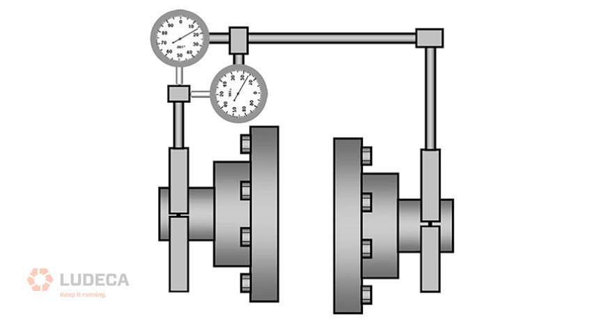
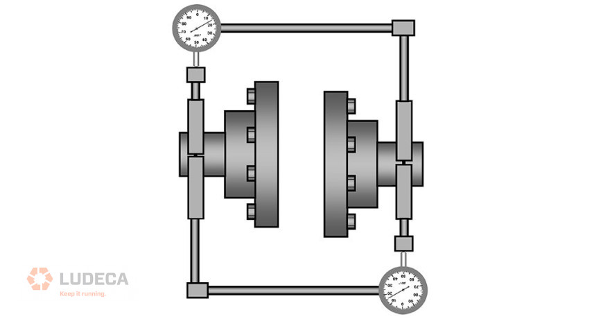
The straightedge could do a fine job with offset misalignment if used with care on coupling surfaces of well-bored couplings; but who could consistently guarantee such conditions? Yet, it was not good enough with regard to the angularity between the shafts. This was due to the limited measurement resolution afforded by eyesight over the short span of the straightedge across the coupling hubs. As apprenticeships and general craftsmanship declined, the assurance that coupling was machined concentric to the mechanical centerline of rotation, and that its faces were perpendicular to said centerline, or even that it was entirely round, waned. Also, foundations became weaker and not as flat as they ought to have been. Put simply, the alignment of surfaces via a straightedge or a dial indicator rotated around a shaft (not with the shaft) was no longer good enough. New ways to align the actual rotating centerlines of machines needed to be devised, and now the dial indicator (formerly strictly a machinist’s tool) came into its own. Its use by millwrights in machinery shaft alignment did not really take off until after WWII. Now the so-called “rim and face” method became king.
Click here to continue reading the entire article: Reduce Errors From Poorly Designed Machinery by Alan Luedeking
Filed under:
Alignment, Articles and Case Studies by Alan Luedeking CRL CMRP