Shaft Alignment is a critical step in any world-class maintenance program, and when done properly, can help decrease unscheduled downtime and keep equipment running longer and more efficiently. This means machines need to be aligned within the recommended tolerances based on the RPM of the equipment. However, this is sometimes easier said than done, especially if any residual soft foot is present, or due to bad geometry in the movable piece of equipment. If you find yourself struggling to complete an alignment to tolerance, here are some tips that, when combined with Ludeca’s 5-Step Shaft Alignment Procedure, may help you complete the alignment faster and with less frustration.
- Get the position of the front feet close to the alignment offset tolerance. Once the front feet are close to or within the tolerance value, complete the alignment by correcting the rear feet only.
- Try to leave both the front and rear sets of feet with positions having the same sign, either positive or negative.
- It is not desirable to leave the position value of the front feet higher than the position value of the back feet. This means that the final position value of the rear feet should be larger in value than the position of the front feet.
The following scenario is an example of how these rules can be applied to help you complete an alignment to precision tolerance as defined by the ANSI standard (ANSI/ASA S2.75-2017/Part 1.) This standard defines three acceptance levels: Minimal, Standard, and Precision. These acceptance levels, as well as the corresponding tolerance values for 3600 RPM, are shown below in Figure 1. The scenario below was prepared utilizing an Easy-Laser® XT770 Shaft Alignment System and the Adjustment Guide feature. Our Easy-Laser XT Series is one of the few laser alignment platforms on the market today with the new ANSI alignment tolerances built-in giving the user the freedom to choose between traditional tolerances, the new ANSI standards, or custom tolerances.
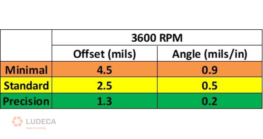
In Figure 2 we have our shaft alignment results measured on equipment running at 3600 RPM, where the position of the front feet is at +1.0 mils and the position of the rear feet is at –0.6 mils. This creates misalignment at the coupling with an offset measuring +2.6 mils, which puts us in the Minimal tolerance range. We need to make some adjustments to improve the alignment in order to reach the precision tolerance range, but how? Let’s try following the recommended tips!
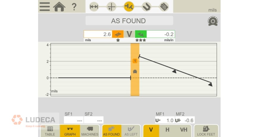
If we look at the position of the front feet in Figure 2 we see that we are at +1.0 or 1.0 mils too high. Since the position of the front foot is already less than the desired Precision Offset Tolerance Value of ±1.3 mils (shown in Figure 1), Tip 1 says we should leave the front feet where they are and complete the alignment by correcting the rear feet only. Looking at the position of the rear feet in Figure 2, we see that we are at –0.6 or low by 0.6 mils. Using the Adjustment Guide feature on the XT770, let’s see what would happen if we add 1 mil worth of shims to the rear feet.
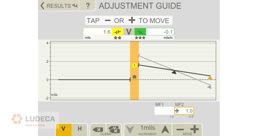
In Figure 3, we add 1 mil of shims to the rear feet of the alignment result that was shown in Figure 2 bringing the new position of the rear feet to +0.4 mils with the front feet still at +1.0 mils. Although both feet now have the same sign, satisfying Tip 2, we see that this still produces an offset measuring 1.5 mils at the coupling, putting us within the Standard alignment tolerance range. Although we did improve the alignment slightly, we still are outside of the Precision alignment tolerance that we are pursuing. What would happen if we added another 1 mil to the rear set of feet bringing the final position of the rear feet to +1.4 mils?
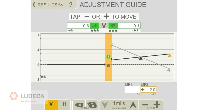
Now in Figure 4, we have added 2 mils worth of shims to the rear feet of the alignment result that was shown in Figure 2, bringing the final position of the rear feet to +1.4 mils with the front feet still at +1.0 mils. Now we see that the position of both the front and rear sets of feet are positive in value satisfying Tip 2. Additionally, the positional value of the rear feet is greater than the positional value of the front feet, thereby also satisfying Tip 3. Now if we look at the misalignment measured at the coupling, we have an offset measuring just 0.6 mils and putting us well within the desired Precision alignment tolerance. In addition, the angularity value has also decreased and is well within the precision alignment tolerance range. Note also that adding shims is always easier than removing them, especially if you do not have enough thickness of shims left under the feet to make the desired negative correction possible.
We hope these three tips will make your task of precision aligning machines much easier.
Request your complimentary copy of our Shaft Alignment Fundamentals Wall Chart which highlights the ANSI/ASA Shaft Alignment Tolerances as well as information and guidelines for the implementation of good shaft alignment of rotating machinery, best practices, soft foot, tolerances, thermal growth, and much more!
Filed under:
Alignment by Tim Rogers CRL