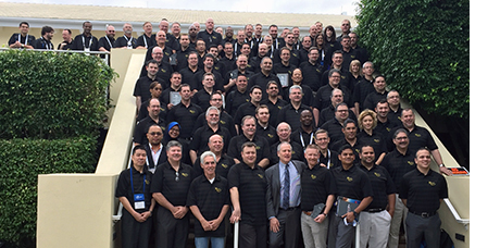
Every year Uptime Magazine recognizes organizations that demonstrate excellence in managing equipment reliability using advanced strategies and technology to determine potential failures and solutions. Last December during IMC-2015 in Bonita Springs FL, I had the pleasure of attending not only the award ceremony but the presentations by the award-winners. It was fascinating to hear them share their pains, the evolution of their programs, their procedures and processes, and the role technology played in the success of their solutions, such as precision alignment and ultrasound, among others. It was personal and very inspirational. I walked away with a few quotes: “Vision without implementation is just a vision.”; “Unity is a powerful thing!”
The buzzword this year at IMC-2015 was “Reliability”. Everybody wants it, everybody needs it but it was made clear that it can’t happen unless we establish Reliability as a set of values, as a belief system for our organizations, remembering that Reliability comes from within, from the people! The award-winners were a testament of these principles with their commitment to Reliability and ensuring that their M&R teams are aligned with their goals and values.
Congrats to all the winners and a very special thank you to our customers Bristol-Myers Squibb, Central Arizona Project, South Gardens Citrus, Merck & Co., Rahway, and Lawrence Livermore National Laboratory for allowing us to be part of their Reliability Journey.
This is an exciting time for our industry and we can all take part in this adventure. It starts with you! Declare Reliability and be part of the culture change.
Some ideas to help you get started:
- Join the Society of Maintenance & Reliability Professionals (SMRP)
- Become a Certified Maintenance & Reliability Professional (CMRP) or Certified Maintenance & Reliability Technician (CMRT)
- Join the Association of Asset Management Professionals (AMP)
- Become a Certified Reliability Leader (CRL)
by Ana Maria Delgado, CRL
An organization’s culture is defined by the manner in which their direct leader treats employees
During their workshop “Uptime Elements – A System for Asset Reliability and Performance Management” at the SMRP-2013 Conference in Indianapolis, Terry O’Hanlon and Ramesh Gulati pointed out that Asset Reliability is an important part of an asset management plan and a key enabler of effective value delivery from assets.
Their message was clear, Reliability is as cultural as it is a technical set of practices and strategies. For over 30 years most of the modern approaches to reliability and effective maintenance service delivery have been well documented yet most organizations fail to achieve sustainable value delivery from these activities. Many stakeholders may not fully appreciate how their work fits into asset reliability and what role their work plays in supporting the aim of the organization through the context of its asset management activities.
A couple of things to know about Leadership for Reliability:
- Reliability is culture as much as it is a set of processes.
- Culture eats strategy for breakfast and leadership sets the culture
The main focus of this learning event was the Uptime Elements which include:
- Reliability Engineering for Maintenance
- Asset Condition Management where our alignment/balancing and vibration analysis maintenance technologies play a key role.
- Work Execution Management
- Leadership for Reliability
- Reliable Asset Management
I encourage you to download and follow the Uptime Elements to develop a holistic system for reliability in your plant and start a new way of thinking about delivering value from assets.
by Ana Maria Delgado, CRL
On May 16th, 2014, the Greater Cincinnati-Northern Kentucky SMRP Chapter hosted its first meeting. “The meeting was a successful one with a great turnout,” said Chapter Founder Bill Schlegel, a past president of SMRP, “I am hopeful we will have an active and involved chapter going down the road.”
The second meeting took place in July at Gateway Technical and Community College. “The meeting started with a tour of Gateway Technical and Community College, which was very impressive. The main topic of the meeting was discussing Technical Skills Development. Presentations were given by Tobin Pospicil, President of Gallatin Steel, Craig Hopkins of AMTEC, and Harry Wagner of Honda. Barry Master of Kroger also shared information about his company’s technical development plans.” shared Tim Jackson with Heartland Industrial Solutions.
The chapter recently met at the Annual SMRP Conference in Indianapolis, IN where they further discussed the chapter’s focus on educating and promoting reliability, benchmarking, networking, transfer of knowledge, collaboration with local colleges, etc.
Congratulations to our local Solutions Providers, Tim Jackson with Heartland Industrial Solutions and Randy Kocher with Machine Development Technologies, for being part of the steering committee.
Membership is free! To join the Greater Cincinnati-Northern Kentucky SMRP Chapter, contact Bill Schlegel
by Ana Maria Delgado, CRL
Every day more and more of the maintenance and reliability community is transitioning into using tools such as LinkedIn, Twitter, blogs, and wikis. There is now a wealth of information out there for those who know how to find it. In his presentation “Who Gives a “Twitter” About Being “LinkedIn” to Reliability? Ways to Improve Plant Reliability with the Internet” at the SMRP-2013 Conference in Indianapolis, Shon Isenhour discussed what these smart people are doing, how they are doing it, and what they are gaining for their efforts.
Shon gave us real examples of problems solved via the Internet and how others can join in to find solutions to their challenges. He wrapped up his session by providing 10 ways to put the Internet to use immediately within your plant. Here they are, in no particular order:
1. For RCA preparation prior to getting the team together, pull equipment documentation and any history available via Google.
2. Search bulletin boards and user group pages for common equipment failures others are experiencing using Google. Verify that these are part of your Equipment Maintenance Plan (EMP) and your Reliability Centered Maintenance (RCM) and Failure Mode and Effects Analysis (FMEA) efforts.
3. Locate spare parts for obsolete equipment via eBay and Google.
4. Locate new vendors and service centers for existing parts via Google.
5. Identify physical defects with pictures of similar failures from Google images.
6. Find equipment vendors’ websites via Google… It is not always so obvious.
7. Read about additional vendor, equipment, part, or product characteristics information on Wikipedia prior to and during an RCA.
8. Follow your common vendors on Twitter to be in the loop with their most recent product releases and updates.
9. Read the blogs of people interested in the same topics or that deal with the same issues you face.
10. Read the various trade publication websites for articles that target the problems you are facing.
Bonus: If you don’t find the answer in any of these places, then post your question to LinkedIn and see what you get.
Thanks to Shon Isenhour, CMRP with Allied Reliability Group for sharing his presentation and knowledge with us.
Visit Shon’s Blog at: www.reliabilitynow.com
Join the LUDECA Machinery Alignment | Vibration | Balancing LinkedIn Group
Follow LUDECA on Twitter
by Ana Maria Delgado, CRL
Yesterday the Society of Maintenance & Reliability Professionals (SMRP) proudly announced the winners for the inaugural CMRP of the Year Award as follows:
Terrence O’Hanlon, CMRP (ReliabilityWeb.com) takes the top honor in the Veteran Professional category. Christopher Mears, CMRP (ATA/Arnold Engineering Development Center) is our Rising Leader winner.
 Mr. O’Hanlon and Mr. Mears were selected by the SMRP Award Committee due to their demonstrated leadership, professional development and accomplishments in the M&R industry. Both will be recognized at a special ceremony during the Closing Session of the Annual Conference on October 16 in Indianapolis. Please join us to celebrate!
Mr. O’Hanlon has spent more than 30 years in the M&R industry. He is co-founder of ReliabilityWeb.com and publisher/founder of Uptime magazine, based in Ft. Myers, FL. Mr. O’Hanlon served as President of UE Systems for 18 years between 1981 and 1999. He has served many volunteer positions within SMRP, including the Board of Directors, Certification Committee and Exam Development Team.
Mr. Mears currently serves as Section Manager of the Asset Management Processes & Technologies Section at Arnold Air Force Base in Tennessee. Among his career accomplishments is the development a CBM/PdM program, which won several industry awards. Mr. Mears holds a Master’s degree in industrial engineering and has served numerous volunteer positions within SMRP, including the 2013 Annual Conference Committee.
Thank you to the SMRP Award Committee for their time and effort!
• Shon Isenhour, CMRP (SMRP Chair)
• Nick Roberts, CMRP (SMRP Vice Chair)
• Larry Hoing, CMRP, CMRT (SMRPCO Chair)
• Kris Goly, CMRP (Body of Knowledge representative)
• Ana Maria Delgado (Member at large)
• Butch DiMezzo, CMRP (Advisor)
by Ana Maria Delgado, CRL
The Hibbing Taconite Company, managed by Cliffs Natural Resources of Hibbing, MN, won UPTIME Magazine’s Best Lubrication Program award. At the heart of their condition monitoring efforts is the Oil Analysis component of their lubrication program, key to helping them identify problems at an early stage of failure.
During the first phase of the program, which they called “First Evolution”, reliability engineers were trained as Level I Machine Lubrication Technicians (MLT1). Thereafter, dedicated lubrication mechanics were assigned to the plants to monitor the condition of the oil. They engaged with their vendors to identify needed parts and reviewed their planning, scheduling, and work execution. They selected critical equipment on which to prove the concept.
During Phase 2, MLT1 training continued, including lubrication mechanics and supervisors. Critical equipment underwent lubrication upgrades with the addition of desiccant breathers, sight tubes, sample ports, and quick couplers for filtering, allowing for safer filter changes and reducing cross-contamination risk.
Today, 80 employees have been MLT1 trained on machinery lubrication and basic oil analysis. Employees are fully engaged and enjoy wholehearted management support as significant consumption reduction was realized. Management views the program as an investment.
During their presentation at the IMC-2012 International Maintenance Conference, Reliability Engineer Dan Lerick shared that in certain applications, they have proved a 3.5% energy reduction by switching to synthetic gear oil, which also extended oil drains from 5 to 15 years. Another positive was the switch to synthetic engine oil where they observed a reduction in fuel usage and fueling time, with an extension in engine life and extended drain and maintenance intervals. Overall ROI was under 1 year!
In addition to their award-winning Lubrication Program and as part of their reliability efforts, the company uses CMMS software and other Predictive Maintenance technologies such as Ultrasonic examination, Laser Alignment with ROTALIGN ULTRA, etc. Learn more.
Congratulations to Dan Lerick and his team for this award and a job well done!
Program Highlights
1) Fluid Analysis consolidated across all Cliff operations. They now use a single oil lab after carefully ranking and comparing sample results from eight different labs. The benefit was consistency and the ability to review and compare data.
2) For Fluid Sampling, they developed sample standards per equipment specs, installed sample ports, and trained personnel on how to collect samples. Their CMMS system controls their sample frequency.
3) The use of Grease Systems and Grease Routes wherever possible along with ultrasonic technology on motors.
4) Implementation of condition monitoring (CM) via oil moisture sensors and CM sensors for real-time monitoring. The immediate benefit was a reduction in overall site oil consumption by removing water contamination.
5) Cleaner and safer fluid changes with the use of dedicated Lube Carts to eliminate drips and spills.
6) All machines were tagged with machine identification and lubrication information to reduce mixing and cross-contamination.
by Ana Maria Delgado, CRL
 MEDIA RELEASE
The AHR Expo and its co-sponsors, ASHRAE and AHRI, have recognized our VIBCONNECT® RF wireless condition monitoring system with an HONORABLE MENTION in the BUILDING AUTOMATION Category of the 2013 AHR Expo Innovation Awards Competition. A panel of Industry Professionals, selected for their knowledge and expertise in HVACR, found our VIBCONNECT RF worthy of this recognition. Representing a broad cross-section of the HVACR marketplace, the winning entries were selected in 10 categories and represent the most innovative new products among the thousands that will be displayed at the show. A panel of judges made up of ASHRAE members evaluated the products submitted based on innovation, application, value to the user, and market impact.
Read the official AHR Expo Press Release.
Winners will be honored during the upcoming HVAC event, the 2013 AHR Expo, Dallas, TX – January 28-30. Register today for FREE exhibit hall pass.
by Ana Maria Delgado, CRL
Thank you for joining us for our Webinar The Field Balancing Mine Field by Greg Lee. We hope you found the presentation to be valuable and very informative. If you missed our Webinar, you can view the recorded version at any time. Watch now!
Here are Greg’s answers to your questions:
Q: Do you have experience balancing cooling towers?
A: Yes. Cooling towers are interesting because there are a number of causes for vibration. One very dangerous condition that can look like unbalance is a cracked hub. This can lead to a catastrophic failure of the hub, allowing the blades to break free and wreak havoc on anything near. I once saw the result of a hub failure that caused the gearbox to break through the wood mounting frame and fall into the water tank. The motor was still running with a 12-inch piece of jackshaft flailing around.
With cooling towers, it is especially important to run a complete vibration analysis before attempting to balance. The customer in the example above had another cooling tower cell with the same cracked hub problem. We caught that one before the failure using the VIBXPERT II vibration analyzer. It was showing a high 1× radial vibration as one would expect from unbalance. In addition, it was showing a high 1× axially, as large as the radial. The spectrums also showed high 5×, 20×, and 25× frequencies as the blades bobbed up and down as they passed the 4 main gearbox supports and the jackshaft. This is derived from 5 blades times 4 supports for 20× and 5 blades times 5 (4 supports and 1 jackshaft) for 25×.
Q: What about a multiplane, multi pickup balance? i.e. Nuclear rotor train, 4 rotors, 8 bearings?
A: I am not sure what your exact question is, but, multiple rotors in a single train can be complex to balance. If the cross effect from plane to plane is large, the complexity grows exponentially. I worked with a field engineer that balanced a long train of 4 generators and 2 steam turbines using the trial weight field balancing method. It took him a week to balance this system of rotors and bearings.
For something as complex and expensive as you describe, I would bring in the OEM or a company that specializes in Nuclear Turbine applications. Because of the number of bearings, they would most likely use a 16- or 32-channel dynamic data recorder versus trying to use a typical two-channel field balancer.
Q: To select a trial weight, is there a ratio between the machine weight to trial weight to get the correct change in phase or amplitude?
A: Many of the companies that produce field balancing equipment have developed proprietary formulas to calculate how much trial weight to use and where to place the weight. The intent of these formulas is to obtain a 30% change in amplitude and/or a 30% change in phase angle. It should be understood that these derived trial weights are guides, not an absolute. In most cases, these formulas take into account rotor weight, speed and the amount of initial unbalance. The instrument then calculates the suggested trial weight and its position.
There are a number of “Trial Weight Formulas” used. For example, the United States Department of the Interior Bureau of Reclamation recommends that the “trial weight should be approximately equal to the weight of the rotating parts divided by 10,000.” Most of the time in the field balancing the weight of the rotor is not known or is at best a rough guess. In these cases, it is advisable to look at the correction weights previously placed on the rotor and use these as a guide.
Q: How do you determine if it is hydraulic imbalance instead of mechanical?
A: By hydraulic unbalance, I take it that you are referring to internal hydraulic forces in a pump. Fans can experience similar interference from wind. Unbalance will manifest itself at exactly 1 time the running speed. The unbalance vibration amplitude will be exhibited primarily in the radial direction. If you see a lot of axial vibration (50% or more of the radial) then you likely have additional problems that are not balance-related.
For hydraulic problems, look for an additional frequency equal to the number of vanes times the running speed. Hydraulic instability in a pump is often seen in spectrums as low-frequency broad-banded vibration below the running speed. Often, hydraulic problems are accompanied by cavitation. There are specific Shock Pulse measurements that will help you identify cavitation.
Q: On a balance stand, ideally you would want to be at running speed. Most of the time this is not possible due to size/mass etc. How much difference does it make if you can only run at slower speeds such as 30% of operating RPM?
A: First, it is important to understand that balanced is balanced at any speed. For an object to be balanced, the rotational centerline and the mass centerline must be the same. This will hold true at any speed. Because of this, it is not necessarily true that the best stand balance is at running speed. For clarification, please refer to the first few slides of the presentation.
Now, to the answer: In general, as long as one is away from the rotor’s critical resonance speeds, it is fine to balance a rotor at a speed lower than running speed. No percentage rule is necessary. Just stay away from critical speeds. With that said, there are some differences between balancing machines. There are two primary types of balancing machines; a Soft Bearing Machine and a Hard Bearing Machine. Both types have advantages and disadvantages.
- Soft Bearing Balancer
A soft bearing balancer allows the rotor ends to move freely in the horizontal direction in the balancing stand. This type of balancer allows the rotor to turn at much slower speeds than the rotor’s operational speed. The balancing procedure is almost identical to field balancing and a calibration or trial weight is used to test the response of the rotor. In this way, each rotor balance is in essence self-calibrated. Like field balancing, multiple runs are required and the correction and trim weights are applied until the rotor meets the acceptance criteria. As long as the speed is above the resonance of the soft work supports, and not at the rotor’s critical speed, the response will be linear and very accurate. Some of the largest steam turbines in the country have been balanced using soft bearing work supports resting on railroad tracks. These rotors are balanced at speeds around 30 RPM. If one is concerned about the number of runs in a stand, then a hard-bearing machine might be preferred. - Hard Bearing Balancer
A hard bearing machine fixes the rotor ends to the balancing stand pedestals. This system only requires one run to determine unbalance and correction weights. A hard bearing stand measures force, rather than motion like the soft bearing machine. If one knows the force and angle of the unbalance plus the weight of the rotor, a correction can be calculated. The advantage is that only one run is required to determine correction weights. However, because the hard-bearing machine measures force directly, the accuracy is sensitive to speed. If the speed of a rotor doubles, the force increases by a factor of 4. Thus the higher the speed, the higher the measurable force and the better the accuracy of the balancing stand. One may be nervous about running rotors such as fans at higher speeds due to wind forces. In this case, a soft bearing machine would be better.
Q: What do you suggest if site balancing requires disassembling the pumps to get access to the impeller, Isn’t it worth doing in a balancing machine in the workshop?
A: Of course, this depends on a lot of factors. If one has to disassemble the pump to add or remove weight, it is probably preferable to remove the pump rotor impeller assembly to a balancing machine.
Q: For which machine sizes are site balancing more effective—small and medium machines or heavy-duty machines?
A: In general terms, the larger a machine, the more expensive and difficult it is to move. Thus the strongest case for field balancing is for larger machines. However, machines like fans can be quite small and easy to access. Field balancing is not limited to large expensive machinery. It really depends on the application and the access to insert correction weights.
Q: Is site balancing a valuable condition to ask for during the engineering and procurement stages?
A: I would recommend that any piece of the new or used equipment being purchased have vibration and unbalance limits included in the specification. I would refer you to the International Standards Organization (ISO) balancing and vibration standards for an internationally recognized reference for vibration standards. If you are in the petrochemical industry, I would recommend looking at the American Petroleum Institute (API) specifications for vibration.
Q: Isn’t a coast down needed to find out if the machine is operating above or below critical speed to get a correct balance solution?
A: Yes. It is highly recommended that one identify the resonances of a machine before attempting to balance. Field balancing at or near the critical speed can cause issues with amplitude and phase measurements. As a general rule, one should stay approximately 20% away from a shaft resonance when balancing. Because field balancing is basically a vector ratio problem, the field balancing technique will work fine for rotors running above or below the critical.
Capturing phase and amplitude during coast-down or startup is one of the best ways to identify the resonant frequencies of a rotor. In the majority of situations, it is preferable to capture a coast down, as the data will not be influenced by the motor torque like it is during a startup. With phase and amplitude data, one can view Bode and Nyquist plots which graphically identify the resonant frequencies.
Another method is to capture a cascade plot of spectrums as the machine starts up or coasts down. Once again, this provides a particularly graphic method to identify a rotor’s resonant frequency.
Finally, perhaps the most common method of identifying resonance is a bump test. This method can be used while the machine is off. If your analyzer supports negative averaging, one can perform a bump test on a running machine. The result shows a frequency spectrum where the peaks represent the resonant frequencies of the object being bump tested.
Q: For what size, speed, and HP machine would you recommend the installation of an external balance disc on the rotor to make field balancing and adding weights easier?
A: If it is the type of machine that would go out of balance often, is expensive to remove from service, does not have an easy way to add or remove weight, or is difficult to move to a balancing stand, I would recommend installing balancing disks.
Q: Have you experienced balancing long shafts where maybe 2 planes are not enough?
A: Absolutely. If a shaft is long and flexible, additional planes may be necessary. There is no hard and fast rule that states if a shaft is 10 times longer than its diameter, additional planes will be required. Often, shafts will be supported by more than 2 bearings. This would generally lead one to balance in more than 2 planes.
Q: I have heard that vibration due to misalignment conditions can be minimized through balancing but that seemed contrary to a remark made during the presentation. Can balancing be effective in reducing machine response due to misalignment? Thanks.
A: The first field job I did was for balancing a high-speed, direct-drive fan. When I got there, an analysis revealed that there was a high amount of fan unbalance, a large amount of misalignment, and a very loose cork base. The unbalance contributed to the looseness and the looseness caused the base to flex and all of these contributed to the misalignment. The looseness contributed to the unit’s ability to vibrate at 1× the unbalance frequency and flex in the frame allowed additional misalignment. The misalignment also contributed to the base looseness and the amplitude of the unbalance. Any machine is a system, and, in this case, each condition made the other conditions worse. They fed each other, but each condition must be corrected to fix the machine as a unit. For example, if the looseness was corrected first, it would have zero effect on the balance. By clamping down the base, more of the unbalance force is transferred to the bearings. If the imbalance is left uncorrected, the bearings will fail early. The unit still needs to be balanced and balancing will not correct the looseness or misalignment. Since the balance is in essence a forcing frequency, the looseness may go down in amplitude but the machine is still loose.
In this case, the first problem to fix was the cork base. It was removed and the fan grouted in, thereby eliminating the looseness. If this were all we did, we would still have unbalance and misalignment. So next we aligned the motor to the fan shaft. Once this was done, the unit was started and the fan balanced.
In a pinch, we could have balanced the fan first. It is likely that the looseness and misalignment would have been reduced, but would still have been present and feeding each other. So I would say that balancing might reduce the symptoms of misalignment but not correct the misalignment. The inverse would be true for correcting the misalignment.
Q: What is the difference between field balancing and using a balancing stand in a motor shop?
A: If the balancing stand is a soft bearing type, very little. The process and math are the same. In the field, there is less response linearly in the structures when compared to a soft bearing stand. Thus, in the field, you can expect to see a little less unbalance reduction when placing correction weights. This effect in the field is minimal.
If the balancing stand is a hard-bearing type, then the shop process is a little different. A hard-bearing system measures force directly. Knowing the weight of the rotor, the RPM, and the force of unbalance, one can calculate the correction. The results are nearly identical to a soft-bearing machine.
Q: We have problems in balancing fans at full operating speed due to operational factors. What percentage of operating RPM should we try to balance at and what problems could we look for not balancing at full operating speed?
A: There is no specific percentage of running speed that will yield better results. If you can reduce speed, then make sure you are not near a resonance where phase angle and amplitude shift. A Bode or Nyquist plot taken during a startup or coast down is best for identifying the resonant frequencies of the fan. Refer to the first few slides of the presentation. When the mass and rotating centerline are the same the rotor is balanced regardless of the RPM.
It is also important to make sure your fan is truly out of balance. On a belt-driven fan, check for sheave eccentricity where the sheave is off-center or out-of-round. This can cause vibration that looks like unbalance. For instance, look for other influences such as air turbulence, unequal blade pitch, and looseness, to mention just a few.
Q: How do you calculate system lag? And will it change based on RPM?
A: By system lag, I assume that you are referring to the balancing system. In the old days, when we commonly used strobe lights to determine phase angle, there was a significant lag in the electronics. By knowing this, we were able to shortcut the balancing procedure and determine the heavy spot of a rotor. Often this lag was about 40 degrees between when the heavy spot passed the transducer and the strobe triggered. With the digital equipment we use today, electronic lag is virtually eliminated. For example, I was balancing a spindle turning 40,000 RPM and was seeing less than 5 degrees of lag.
The easiest way to determine your instrument’s lag is to get a rotor that is balanced, place a weight at a known position, and see your instrument’s result. By using the field balancing procedure built into today’s modern balancing instruments, lag is automatically compensated for in the balancing procedure.
Q: How to distinguish couple unbalance and quasi-static unbalance?
A: Look at the phase angle of each plane. If they are the same, it is purely static. If they are 180 degrees opposite from each other, it is pure uncouple unbalance.
Q: What is the maximum level of vibration at which we can perform in-situ Balancing?
A: There is no set amount of unbalance where we cannot perform a field balance. Of course, one must apply a little logic. If the vibration is so bad that it is causing damage, then it might be wiser to pull the rotor and place it on a balancing stand.
Q: Is there any procedure to perform single-shot balancing rather than 4-run method?
A: For a single plane balance, it requires 2 runs to secure a solution and an additional run to verify the result. With a two-plane balance, it takes 3 runs to secure a solution and a 4th run to verify the result. Normally, in the field, this is the best approach.
On a journal bearing machine where the masses are known and the heavy spot is verified, one can calculate how much weight is needed to reduce the vibration. This would only take an initial measurement to determine. However it is rare that we know the precise weight at each bearing, and even this process often takes multiple runs.
Q: Must the 30 -30 rule be followed for on-site balancing?
A: In the words of Captain Barbosa “…the code is more what you’d call guidelines than actual rules.” The 30-30 rule is under ideal conditions. I have balanced where I got the phase exactly right so the trial weight change was more like 0 degrees and a 15% amplitude change.
Q: If we change angle of blades of cooling towers, will it have any effect on balanced impeller (During balancing let’s say we have 11 degree angle of blade, and then we have to change angle to 7 degrees because of process requirement)?
A: If one blade’s pitch is off relative to the other blades, it will look like unbalance. However, this condition would be accompanied by a lot of axial force at a frequency of 1× because of the unequal blade pitch. If it is pure unbalanced, then the axial force would be steady and not have a large 1× frequency component. So, in your example, as long as the blades pitch the same amount and the aerodynamic lift changes equally on all blades, the rotor will still be in balance.
Q: Do quasi-static unbalance and couple unbalance have the same solution or something else?
A: You seem to be mixing terms. When using a two-plane balancing technique, the program takes into account the cross effect between planes A and B. Separating the static and couple balance is possible, but with the accuracy of today’s instruments, it is rarely done.
Q: Is there any effect, if we put the trial weight at 75% RPM and then the correction weight at 85% RPM?
A: The context of your question is not clear to me. I think you are saying, if the speed changes during the initial measurement, trial weight measurement, and correction measurement, will this have an adverse effect. Yes, changing speeds can create problems with the field balancing vector solution. Sometimes it is impossible to take measurements at the same speed, and, the more this speed varies, the less accurate the balancing solution will be.
Q: Could you please go over the “no phase balancing” variation that you talked about in more detail?
A: To review the process would require an article. This process is primarily used on single plane problems. There are 4 steps required to calculate a solution.
- Take an initial amplitude measurement.
- Place a known amount of weight at zero degrees and take a second amplitude reading.
- Remove that weight and place it at 120 degrees. Take the third amplitude reading.
- Remove that weight and place it at 270 degrees. Take the third amplitude reading.
- This data can be plotted on polar paper to determine a solution.
There is more information on this process available on the Internet.
Q: Rather than try balancing at near-critical resonance speed, would it be beneficial to try and stiffen the structure to move resonance away from balancing and operating speed?
A: Yes this can be, and is done. Many times it takes a lot of stiffening or adding mass to significantly shift a resonance. Changing speed is easier, if possible.
I once balanced a large vertical fan in a 40-foot high tower. The tower was resonating and causing problems. We loosened the guidewires going to the top of the structure to decrease the stiffness. This lowered the resonant frequency and helped us achieve a good balance.
by Yolanda Lopez

We just returned from the Electrical Apparatus Service Association (EASA) Convention & Exhibition where we showcased our latest products for the electromechanical industry. We were busy talking and demonstrating our equipment to customers and prospects eager to learn about our maintenance solutions. The favorites this year were our new VIBCONNECT RF wireless condition monitoring system and our new VIBXPERT® II field balancer.
Many of our loyal customers came by our booth to see the latest but also to share their success with us. One of our happy customers stated:
“I love my ROTALIGN® ULTRA, this tool made me what I am. My customers ask for me to come to their facility for laser alignment because they know that my alignments with this tool are perfect!” —C.I., Rotalign ULTRA user at an Electric Motor Shop in NJ [Company/name withheld by request]
by Ana Maria Delgado, CRL
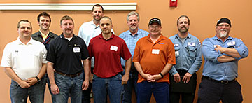
The Associated Builders and Contractors (ABC) announced the winners in its 2012 National Craft Championships competition, held at the association’s EdCon & Expo, April 24-27 in San Antonio.
“ABC is honored to recognize the winners of the National Craft Championships for their high-quality workmanship, technical knowledge and safe work practices,” said 2012 ABC National Chairman Eric Regelin, president of Granix, LLC, Ellicott City, Md. “These craft trainees are the best of the best and show us that there is a bright future ahead for ABC and the U.S. construction industry.”
A field of 127 craft trainees competed for top honors in 12 competitions representing 10 crafts. Competitors first took an intense, two-hour written exam and then competed in daylong hands-on practical performance tests in: residential/commercial carpentry; residential/commercial electrical; commercial/industrial electrical; fire sprinkler; HVAC; insulation; millwright/industrial maintenance mechanic; pipefitting; plumbing; sheet metal; pipe welding;and structural welding.
 Congratulations to the winners of the Millwright Competition:
Gold: Kurt Dickinson
Training Sponsor: ABC Maine Chapter/Cianbro Corporation
Employer: Cianbro Corporation
Silver: Harold B. Harris III Training
Sponsor: ABC Pelican Chapter
Employer: Turner Industries Group, LLC
Bronze: Seth Norton Training
Sponsor: ABC Maine Chapter/Cianbro Corporation
Employer: Cianbro Corporation
LUDECA is proud to have sponspored and supported the event with several SHAFTALIGN laser shaft alignment tools for the Millwright competition.
We can’t thank LUDECA enough for all of your help again this year. It was a great event! —Lisa Nardone, Associated Builders and Contractors
by Ana Maria Delgado, CRL
TransAlta from Alberta, Canada won Uptime Magazine’s Best Vibration Analysis Program. Their Vibration Journey started when due to distance and the high costs of using a contractor, they moved away from outsourcing their vibration analysis services to a full-time in-house vibration analyst.
During the implementation and mentoring period, and in spite of the business justification, they faced challenges like skepticism from the maintenance department and having to continually justify their existence. Buying and implementing new technology was easy but changing the culture was difficult. Some of it was overcome with their ability to be 100% correct on the calls they made for failures although at the beginning they did not catch all the failures. 10 years after their vibration program started, there are no more skeptics.
An important element of their success was the implementation of a training and certification program with a budget that allowed for 2 weeks of training per year per analyst. They also required that personnel take CMVA Level 1 (Canadian Machinery Vibration Association) or equivalent followed by Level 2 after 18 months and Level 3 within four years on the job.
Aside from bringing Vibration Analysis in-house, they also implemented other in-house programs such as Laser Alignment, Balancing, Ultrasound, Lubrication, and Thermography.
What did they accomplish? Savings of US$ 4,000,000 per year for their company over 1,600 pieces of equipment at 3 separate plants.
When first asked about their program, Mark Kumar told Terry O’Hanlon, publisher of Uptime Magazine, that their Best Asset was their vibration database (history) which allowed them to diagnose failures but now in retrospect, he stated that their Best Asset was the Backing of Company Management which supported their initiative for an in-house vibration program.
Congratulations to Harvey Henkel, Mark Kumar, and their team for this award and a job well done.
by Ana Maria Delgado, CRL
Domtar Espanola from Ontario, Canada won Uptime Magazine’s Best Asset Health Management Program. Their goal was “Go from Reactive Maintenance to Proactive”.
To achieve this goal, they put together a plan including several proactive actions and PdM technologies integrated with an Asset Performance Management Software which allows them to closely monitor equipment health. Kim Hunt shared some of their plan elements:
- Implement a precision lubrication program and oil analysis
- Skills training: Value your staff and empower them with training. From formal training to just watching Reliabilityweb Webinars together and afterward eating cookies and holding discussions —great for team building!
- Size your equipment properly
- Use laser alignment and balancing for precise machine rebuilds and installs
- Precise operator care
- Maintain excellence in housekeeping
- Equipment health monitoring. Use predictive tools, primarily vibration analysis to baseline your equipment.
- Root cause analysis and problem elimination
- Plan and schedule your maintenance activities with effective standard operating procedures
- Continuous improvement – you are never done!
What did they accomplish?
- 21% reduction in maintenance costs
- 30% increase in production efficiencies
- Increase MTBF (Mean Time Between Failure)
- A total average savings of US$450,000 per year without actual/potential product loss.
Congratulations to Kim Hunt and her team for this award and a job well done.
by Ana Maria Delgado, CRL
 One hour-long presentation by Ray Wonderly, Retired from General Motors Corporation, Owner of Advanced Maintenance Technologies. Originally filmed at the CBM 2011 Condition Based Monitoring Conference at the Reliability Performance Institute in Fort Myers, Florida.
This discussion will focus on the use of Vibration Analysis to verify machinery problems or faults, primarily misalignment. Case studies will be presented to highlight the benefits of using Vibration Analysis systems for the early detection and verification of misalignment problems and the use of Laser Alignment systems to correct problems found.
After corrective actions are performed and problems eliminated, new vibration measurements should “always” be taken to confirm satisfactory results. The intent is to illustrate how Vibration Analysis can save valuable time when used in conjunction with Laser Alignment to verify the root cause of problems found and to confirm satisfactory results.
We’ll also discuss common characteristics of misalignment, different types & causes of misalignment, and things to consider when performing precision alignment of equipment.
Classic “textbook” case histories will be presented (as time permits) of misalignment problems along with some factory floor case history examples to illustrate unique situations when special vibration measurements such as high resolution or high-frequency instrument setups were needed and proved very beneficial in determining the true source or “root cause” of machinery problems.
A case history involving acceptance testing of a recently rebuilt 800 hp 2-pole motor & Centac Compressor will be presented where the true source of excessive vibration levels was questionable in terms of whether they were more related to mechanical (misalignment) or electrical vibratory forces.
Watch Vibration Analysis and Laser Alignment “Technologies Working Together”
by Ana Maria Delgado, CRL
The HRSG User’s Group steering committee honored seven long-term participants in the organization’s activities as Steam Plant Mentors for their significant contributions over the years. Executive Director Rob Swanekamp explained while presenting a customized vest to each mentor,
Because the training at our conference so heavily relies on audience participation, these loyal attendees provide the real education to HRSG users.”
 The mentors named are the following:
First row (l to r): Howard Moudy, National Electric Coil; Mike Hendrick, Conval Inc. Swanekamp is at the far right.
Second row: Craig Stephens, Denver City Energy Associates; Yogesh Patel, Tampa Electric Co; Jorgen Gertz, Puffer-Sweiven.
Third row: Daus Studenberg, LUDECA Inc; James Whitehorn, Maxim Group.
by Ana Maria Delgado, CRL

As the Project Manager for the Millwright Competition and a member of the 2011 ABC Craft Championship Committee, I want to thank you and your company for your support for the Millwright competition.
Even though I have never used that particular laser, it was very easy to use and only took about five minutes to become very comfortable with it. None of the competitors had used the SHAFTALIGN® prior to the competition, which was great. It only took about twenty minutes to show them how it operated, including thermal growth, soft foot, and static feet selection. Even though the competition required an 1800 rpm alignment with thermal growth, one of the competitors did a 7200 rpm alignment within the time limitation, which would never have been achievable with dial indicators.
I am proud to say that with your help and equipment this competition has finally evolved into a modern competition. Your alignment equipment is easy to install, easy to use, and accurate. It is the best alignment equipment that I have ever seen.
Again thank you for your support.
Ed LePage
Mechanical Craft Training Coordinator
CIANBRO Institute
Congratulations to Joseph Ducharme, the first-place winner.
by Ana Maria Delgado, CRL
Take a look at what it takes to become a certified maintenance and reliability professional.
One time-honored way to lay claim to proficiency in a body of knowledge and the respect that comes with it is certification. From doctors and lawyers to real estate agents and pest-control specialists, earning or buying impressed pieces of faux parchment suitable for framing, the right to add a string of initials after one’s name and the pleasure of regular renewal obligations have been beneficial to career success, if not an outright requirement, of doing business in a given profession.
Read the entire article: Are you certifiable? | Plant Services.
by Ana Maria Delgado, CRL
We would like to extend a special thanks to those who attended the Facilities Tour in our Doral Training Center on Tuesday. The event started with an overview of our company by Frank Seidenthal followed by a keynote presentation “Getting Maximum Value from a PDM Process” by Bill Hillman. Reliability 2.0 attendees were given a tour of our facility including our NUPIC approved calibration laboratory and they also had the opportunity to interact with the measurement instruments at our various maintenance technology stations featuring dedicated equipment for machinery alignment, vibration analysis, balancing, bearing heating as well as specialized systems and simulators for more demanding measurement applications such as bore and turbine alignment, flatness, straightness, and leveling. All stations were equipped with dedicated systems for hands-on experience with the benefit of guidance and assistance from our attending application engineers. We look forward to our next event and to serving your alignment and condition monitoring needs. We leave you all with Bill’s closing statement:
The Key to Success We can train. We can change the way we talk. We can change the way we think. BUT! UNLESS WE CHANGE WHAT WE DO, ALL THE REST IS ONLY BACKGROUND NOISE.
Download keynote presentation “Getting Maximum Value from a PDM Process”
View LUDECA Facilities Tour 2010 photos
by Ana Maria Delgado, CRL