Often, when I get a report or a technical support call, if I see the user got a perfect “0-0”, I become immediately suspicious rather than celebratory. What I mean by “0-0” is that the coupling results or feet corrections (or both) are perfect zeros. There are times where that is possible, for example, this screenshot of the alignment that was taken out in the field as shown below:
The numbers are close to zero, but not exactly zero. The point is there is at least some variation. Assuming the resolution is set to the nearest 0.1 mil, “0-0” would mean that that alignment is less than 0.1 mil, a very rare and impressive achievement!
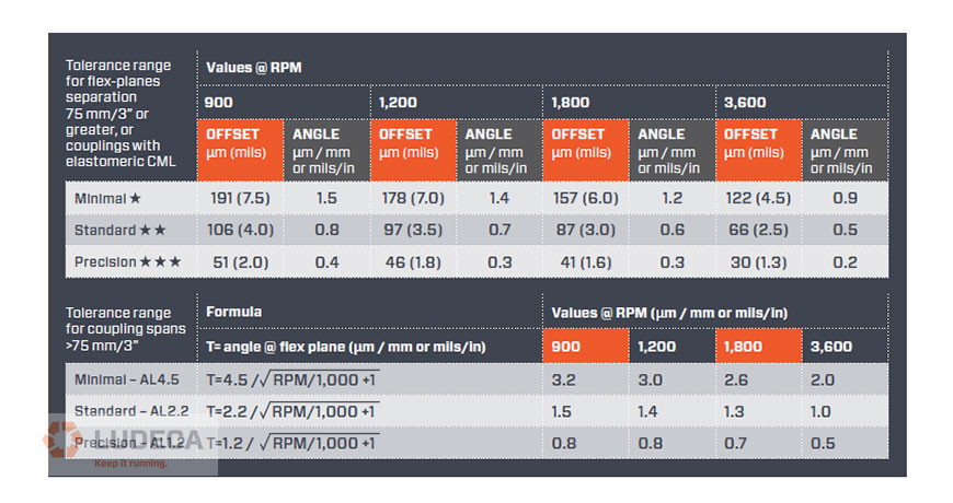
Is “0-0” necessary? The answer is no because you have a shaft alignment tolerance for a given speed of rotation. Lower rotation speeds require looser tolerances and higher rotation speeds have tighter tolerances. Tolerances are to be used to your advantage so you know when to stop the alignment. If the goal is perfect zeroes, it could be possible, but you will be working way too long to achieve a nearly impossible goal. We suggest the use of the ANSI/ASA S2.75-201 standard tolerance as shown below:
Click here to review and purchase your ANSI-ASA-S2.75-201 Shaft Alignment Methodology, Part 1: General Principles, Methods, Practices, And Tolerances
What happens if you do get “0-0” for your alignment? I would advise checking the following to make sure this was not a user setup error:
Check the resolution. Is it set to 0.1 mil resolution (recommended)? If it is set to 1.0 or even 10.0, the lowest number will default to zero.
Are you using the correct units? (i.e. metric vs imperial)
Is the measurement shown to repeat in the measurement table? Is the alignment measurement reproducible?
Were the sensors mounted on each machine shaft? Never mount the sensors on the coupling part that flexes, or you will get an incorrect reading. If you mount on the coupling only, this doesn’t represent the alignment between the machines; you will have an incorrect setup and most likely show perfect alignment.
If you have a solid boss fit style rigid coupling, make sure the boss fit is separated to disengage the coupling with the bolts slightly loosened. This allows the misalignment to be measured. If the coupling is bolted, the shafts will be forced together, showing an incorrect near-perfect alignment.
Request your complimentary copy of our Shaft Alignment Fundamentals Wall Chart which highlights the ANSI/ASA Shaft Alignment Tolerances as well as information and guidelines for the implementation of good shaft alignment of rotating machinery, best practices, soft foot, tolerances, thermal growth, and much more!
Correcting a shaft alignment problem brings a vast set of challenges to the workload of our mechanics, millwright, and engineers. Those issues could be in the form of physical constraints preventing movement or distortion from poor bases or pipe stress. They could be as simple and frustrating as soft foot or old bent shims. But, one of the most intimidating alignments out there is the spacer shaft, especially when it comes to extreme distances.
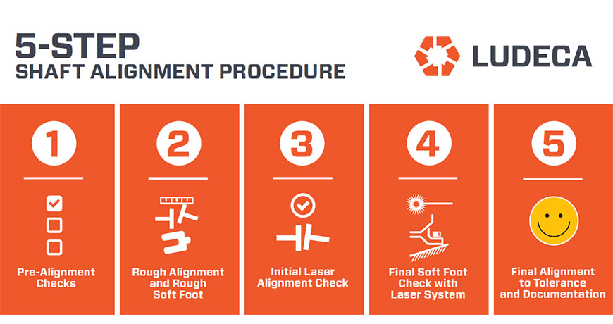
I am not an engineer—oh-oh, half of my readers just left—but for those of you still reading, I want to provide you with a few tips compiled by a few of us here at LUDECA to make your spacer shaft alignments with lasers easier. So, without wasting too much of your time, I refer you to the 5-Step Shaft Alignment Procedure.
Just kidding… sort of.
There are many different types of spacer shafts. So, what is a spacer shaft?
Picture 1
Generally speaking, a spacer shaft (spool, spider, jackshaft, or whatever you want to call it), is a coupling of some kind that spans more than 4″ or 101.6 mm between its flex planes. My goal in this blog is to provide five simple tips to help you align spacers without getting into the mathematical process. I’ll save those questions for the engineers. Keep in mind, these are suggestions for laser alignment of spacer shafts.
Spacer Shaft Tip 1:
Try to make sure you can square the two sensors to one another. By either using the inclinometers, lasers to targets, or really good eyesight – it tells you a lot if your sensors square up to one another. This seems like a simple or obvious tip (which is why it’s the first one) but, this also provides you with an indicator for TIP 2!
Spacer Shaft Tip 2:
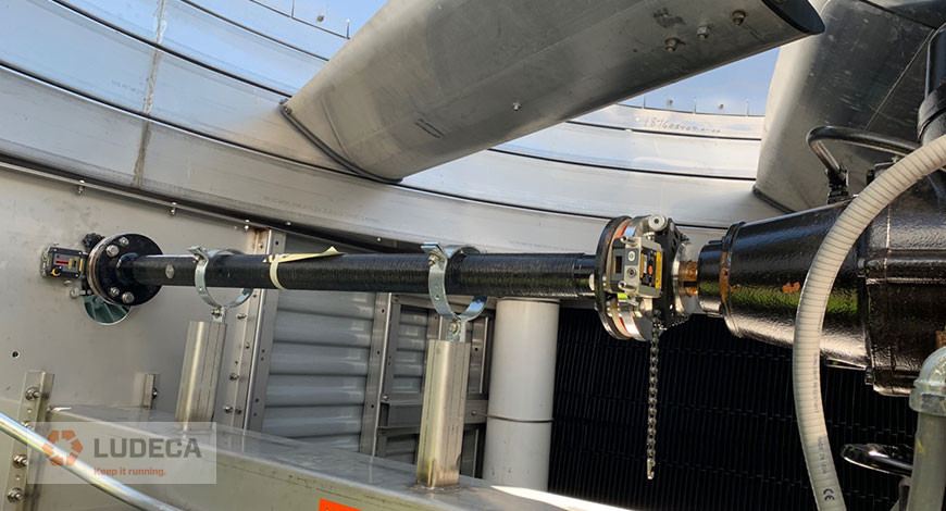
There are two primary ways of aligning spacers: the Two-Step Method and the Single-Shot Method. Now that you can determine how bad your misalignment is – you can choose the method that fits best. The single-shot method is typically done when the alignment isn’t grossly out and the sensors would be mounted on the far ends of each spacer component. The two-step method is used when there is a significant amount of angle or offset to correct. The sensors should be mounted across each flex plane of the spacer individually to close the angle at each.
Picture 2
Spacer Shaft Tip 3:
Soft Foot. If you are following our 5-Step procedure you probably understood that I went a little out of order. However, we needed to know which components we were moving first, right? Now that we have a plan we have a procedure. Soft Foot matters, and it should be corrected and fall within the allowable tolerance. Use this time to also correct any challenges that can be identified visually (clean the base, good shims, etc.) You may want to take a look at our Soft Foot Find and Fix Procedure for an outline of types of Soft Foot including causes and corrections.
Spacer Shaft Tip 4:
Know your tolerances. There are 1,001 blogs and articles on spacer tolerances on the web. The best thing you can do is know what your tolerances are for that specific alignment. Yes, spacer tolerances can be more forgiving in terms of the required corrections at distances. However, there are many ways to represent those spacer tolerances. You could have a specification that is Angle/Angle or Offset/Offset or a combination of those. Make sure you are aware of the required values and representation.
Spacer Shaft Tip 5:
Patience. Don’t rush to get it done. Do it right so you don’t have to do it again.
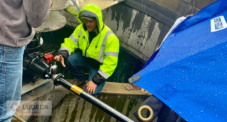
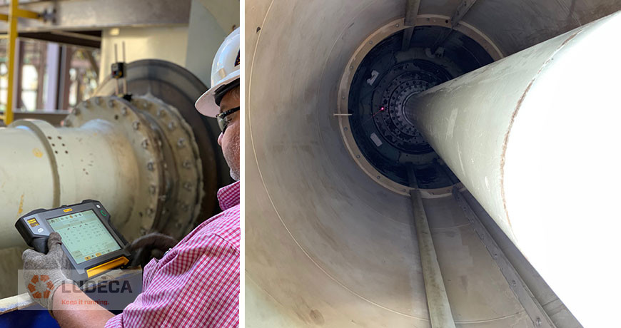
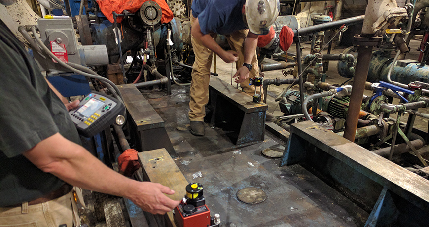
Picture 3 and 4
So, when you find yourself facing a spacer shaft, spool piece, or jackshaft, take a deep breath and follow the same rules of alignment that experience has taught us. I would also like to thank Joel Chapman from Entech Sales & Service Inc. for a lesson in cooling tower alignment in the rain (the umbrella was for me, not the laser, it was very nice of him – picture 2). And, thank you Richard Armstrong of TRACE Reliability, a LUDECA, INC. solutions provider who makes our customers a priority. He shared pictures 3 and 4 of an ID Fan in Louisiana that measured 289” inches from sensor to sensor.
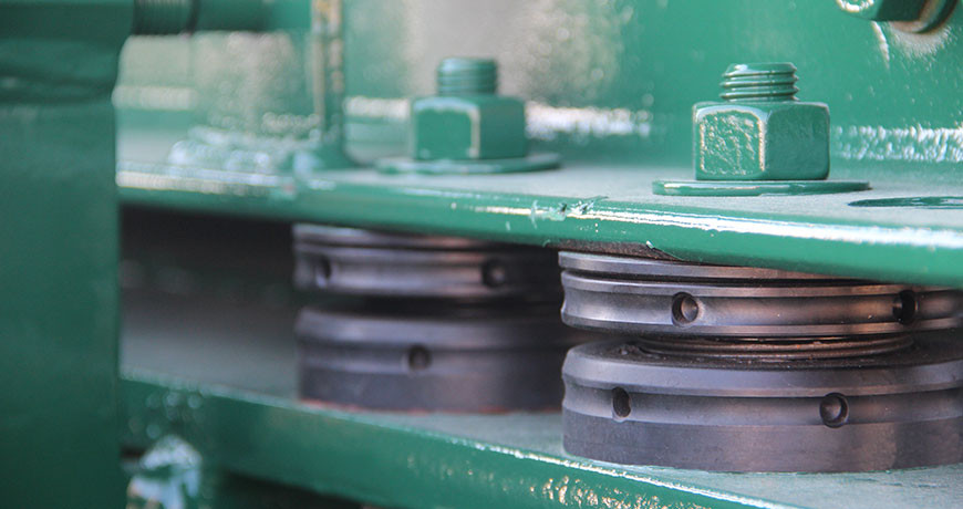
Adjustable chocks have been around for years and are a useful way to accomplish parts of machine mounting and alignment. In some circles, they have either a great or bad reputation. A lot of that reputation may depend on the application and how the chocks were installed.
Adjustable Chocks vs. Shims
First, let’s discuss why a company might want to use an adjustable chock for machine mounting, instead of shims:
Adjustable for height. This means not having to stock lots of shims, in different sizes and thicknesses, to accomplish vertical adjustments in alignment.
Spherical top part. This accommodates issues with feet not being parallel (up to 4 degrees for some manufacturers) with the foundation or skid which eliminates the need for step shimming.
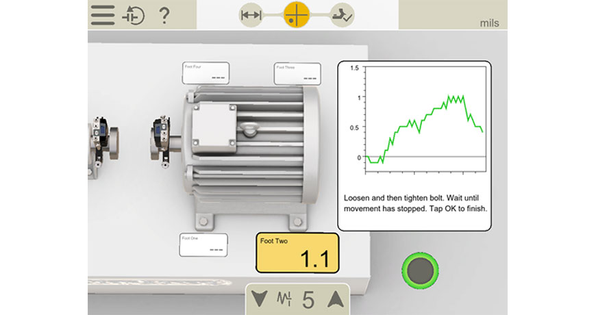
Easy Soft Foot corrections. When an air gap is found, simply fill the gap by adjusting the chock to fill the gap. (Zero Soft foot)
Reduced inventory. Instead of several shims in a kit for each piece of equipment, just reuse the existing chock for adjustments.
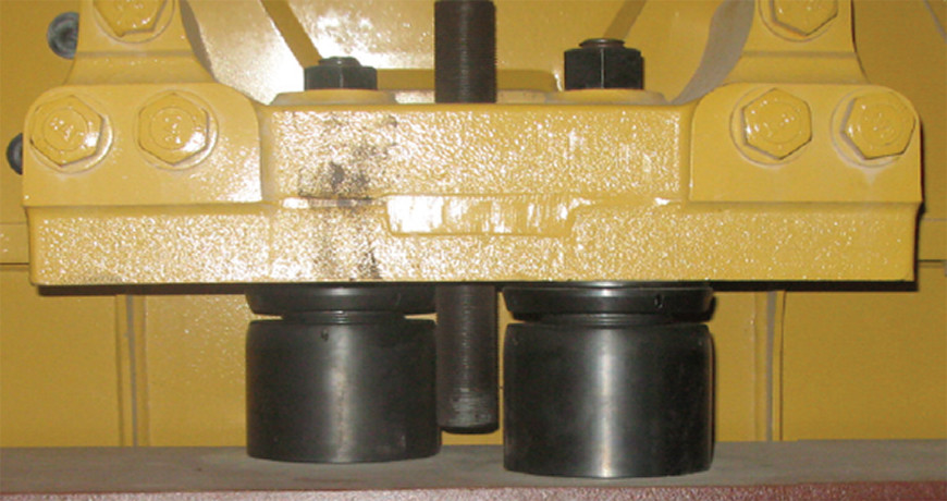
Now, let’s discuss why a company might not want to use an adjustable chock for machine mounting, instead of shims:
Lack of contact surface between mounting foot and base. How can this round element take the place of a full-footprint shim for secure mounting?
Transmission of Energy. Without the solid contact of that full-footprint shim, the energy will never be transmitted to the Inertia Block in the base; therefore, the equipment will shake itself to pieces.
Locked up chock. Once they have been in service for a while, they lock in place and have to be replaced for future alignments.
Loose chock. Upon inspection, the chocks have been found to be rotated down under the foot, and there is a gap/Soft Foot condition.
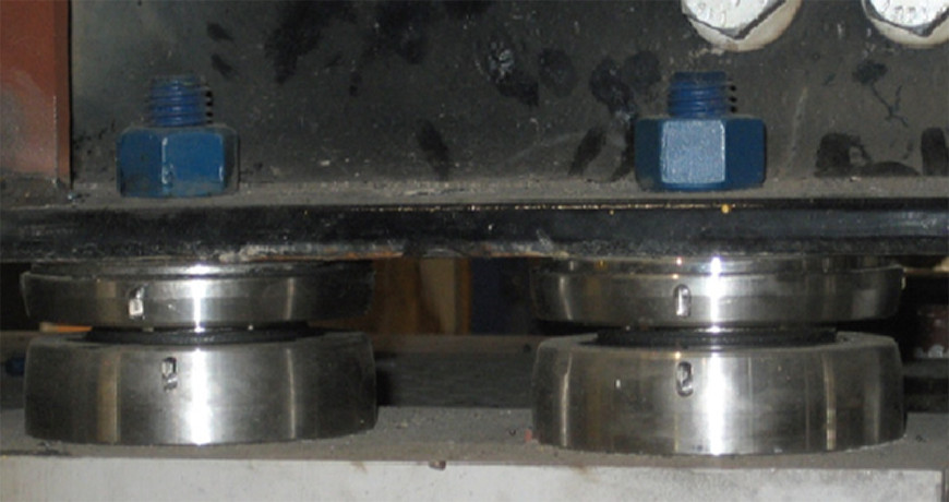
The Cons of Adjustable Chocks
By looking at each of those concerns, answers can be found for how to mitigate the concern and better understand how adjustable chocks can (and cannot) be used. The design and engineering of these devices make them suitable for most applications, but not if selected and used incorrectly.
For the issue of lack of surface area under a foot to the mounting base, looking at the product catalogs show any number of configurations to increase the surface area. Using more than one at each foot, or having two under a foot but staggered. The simplest rule to use is to use the largest chocks that can fit, but with a catch. The top surface must cover at least 75% of the surface area of the mounting foot, and the bottom surface must have 100% of its surface area in contact with the base. Both of these surfaces must be clean.
This leads to the next issue, the transmission of Energy. If the correct size of the chock is selected, and the above rule for coverage is observed, then the Energy will transmit through the body of the chock just fine. The other thing to watch for is cleanliness. Both the bottom of the mounting foot and the top of the base should be clean – reasonable steel-of-the-truck finish (corroded, excessive mill scale, or moon crater need attention, with a minimal primed surface for corrosion purposes. Any amount of paint, dirt, or debris can make for an uneven surface that could result in the bottom of the chock not sitting squarely. Sometimes, a bit of light sanding can go a long way towards promoting proper machine mounting. Check with chock manufacturer for surface finish recommendations.
Now, for the locked-up chock. Oftentimes, comments are made that the machine being aligned is unable to be lifted by the adjustable chock. This is a misconception. The threaded chock is designed to lock under load. It is NOT designed for lifting or lowering the equipment. Normally, equipment that is designed correctly will have vertical jack bolts, and this is what is used to establish the correct elevation for the machine, or, in their absence, use a hydraulic pancake jack or other suitable lifting devices. Beyond that, finding the chocks unable to rotate after being under a piece of equipment can usually be attributed to dirt and debris in the threads. It is a very common practice to lift the equipment on the vertical jack bolts just enough to remove the chocks. Thorough cleaning in a general solvent can remove the particles that restrict movement. After the cleaning, a thin coat of appropriate lubricant (often a specific compound recommended by the chock manufacturer) will help ensure movement. Protecting the cleanliness of the chock after alignment can be accomplished with a heavy protective spray. Anything that seals moisture and debris out is good, as long as it does not trap moisture (just to note: whatever you put on it will need to come off at some point to allow the chock to be reusable – be judicious or better yet contact your chock supplier).
Lastly is the concern of loosened chocks, which has been a topic of much discussion lately. The easiest way to explain this problem goes back to proper training. The technician performing the alignment needs to be mindful of how an adjustable chock is designed to work. The function of that chock is to support the machine. Prior to torquing the hold-down bolts, the machine needs to be resting on the chocks, not on the jack bolts.
The procedure boils down to using the jack bolts to establish the correct elevation, spinning all of the adjustable chocks up to firmly contact with the bottom of the machine, and then perform the final tightening. (Fit all chocks at the same time!!) Back off all lifting and lateral adjustment jack bolts FULLY, then tighten the anchor bolts to the proper torque in the sequence specified by the equipment OEM
Do not tighten the anchor bolts with the jack screws or lifting bolts under load!
The purpose of adjustable chocks is to facilitate proper mounting of equipment, more efficient alignment operations, and a viable replacement for traditional shims. While they might not work for all applications, with proper implementation chocks can work for 90-95% of applications where larger spacing between the machine feet and the mounting base is required; rather than inserting a big pile of shims, a chock can make life easier for the technicians performing realignment. This requires an open flow of information from the design and installation of the equipment, all the way through to the day-to-day maintenance.
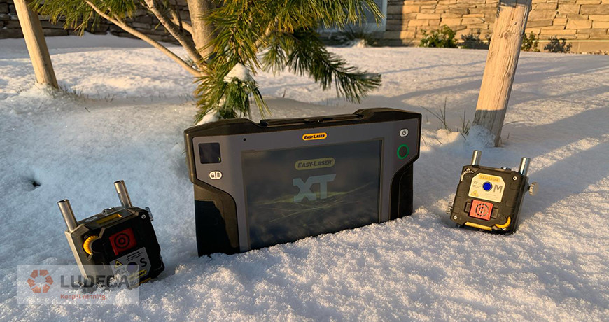
The consequences of positional change due to thermal growth in machinery as it pertains to shaft alignment are well documented. Methods for determining these changes and compensating for them are not only essential to the reliability of machines but can prevent catastrophic failure. It is therefore of great importance that these methods be carried out as carefully as possible—minimizing human error as much as possible to ensure effective results.
One often-overlooked consideration when performing shaft alignment measurement is the temperature and thermal stability of the very components used for these measurements. Brackets, lasers, sensors—all components that are susceptible to thermal growth. Changes in the intensity of sunlight, large shifts in ambient temperature during the job, and performing measurements too soon after bringing the components out to the machine can all lead to lack of repeatability and improper shaft alignment corrections.
Photo credit: Brian Franks with JetTech Mechanical LLC.
You can minimize the effects of these conditions in various ways:
Always allow a suitable amount of time for the alignment system to acclimate to the environment in which you will be performing the measurements. For example, if the equipment is moved from a warm office or truck to a cold environment and measurement is begun immediately without giving the temperature of its components enough time to stabilize, performing the shaft alignment will be a bit like trying to hit a moving target. The brackets and/or laser and sensor housing will still be physically changing in dimensions until stabilization has occurred.
If sunlight conditions are unstable where you are working try to keep the alignment components shielded from the sun. Direct sunlight striking the laser housing of a shaft alignment system can have an adverse effect on the reliability of the readings during a measurement.
Keep portable heaters and air conditioning units away from the area. It is natural to want to work in a comfortable environment, but the unstable air currents caused by heaters or a/c’s can wreak havoc on measurement repeatability.
And one more: if a heat source is intense causing heatwaves in the path of the laser beam, thereby distorting or refracting the laser beam and affecting your repeatability, a simple fan to blow air through that area can help to stabilize conditions or provide a uniformly turbulent atmosphere for the laser to travel through, allowing its true position to be accurately averaged.
Observing these principles while performing shaft alignment readings will allow you to achieve more stable and reliable results and thus help you to #keepitrunning.
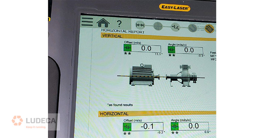
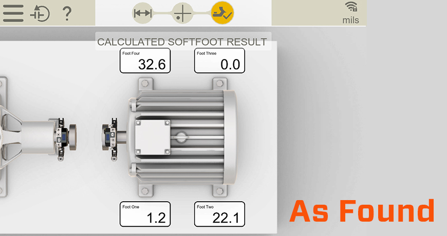
On a recent visit to a power plant, they asked me to help them align a pump with their new EASY-LASER XT Alignment System. It was a machine they had previously aligned with dial indicators, which they thought was “pretty good”. The initial measurement showed a vertical offset of about 7 mils, so we removed all the shims and measured soft foot. The results are shown below.
As you can see, there was a significant issue. We probed and found gaps under both the indicated feet. The foot showing 32.6 mils showed a parallel air gap, whereas the foot showing 22.1 mils had an angular gap that required step shimming.
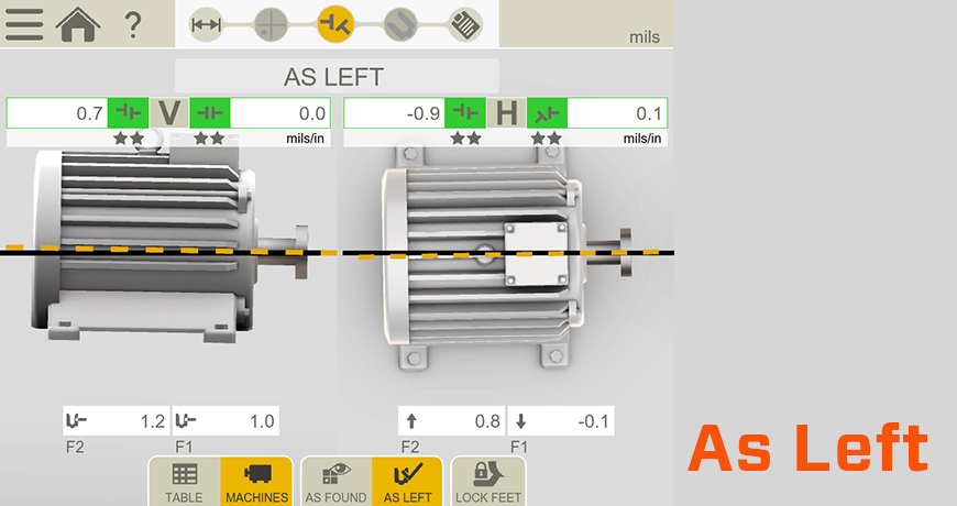
Once the soft foot was corrected we continued with the alignment, and achieved excellent results.
In a later conversation, I learned that the motors had been too high for the pumps when installed, so the contractor ground down the feet with a wheel grinder! That explains the soft foot issue!
Bottom line, ALWAYS check soft foot. Not only does uncorrected soft foot make the alignment more difficult, it introduces stresses to the machine thus reduces reliability.
Download our Soft Foot: Causes, Characteristics and Solutions white paper for additional information that explains in depth the causes and characteristics of soft foot conditions and how to diagnose and solve them.
Many shafts have keyways cut into them to hold the coupling. “Keys” are pieces of square metal stock inserted to hold the hub in place.
If there are two (2) keys, one on each side of the coupling, you should not “align” the keys across the coupling. Instead, it is very important to ensure the coupling mass is balanced during installation. The mass of a key is balanced by setting the two keys 180 degrees apart from each other. If the keys are set on the same side, the coupling will induce a mass unbalance situation.
Often a vibration report will note a misalignment condition, but precision alignment techniques will not find any issue. This can lead to friction between the vibration analyst and the millwright. Keep the keyways 180 degrees apart. You will help improve the life of the coupling and keep the vibration low.
Today’s advancements in technology have allowed many maintenance tasks to be performed more easily and efficiently. Such is the case with using a laser alignment system to accomplish sheave/pulley alignment. However, prior to setting up the laser system to perform the alignment, one important and often overlooked step is to measure and correct sheave run-out. Run-out refers to the situation when an object does not rotate exactly in the plane of the main axis of rotation. If not corrected, sheave run-out can cause a “rubber band effect” where the belt will become slack at one end while the other end quickly snaps into tension. Over time this repetition of the belt going slack and then tightening will wear out the belt as well as the bearings and cause premature failure.
Run-out for sheaves can occur in two forms, radial (rim) and axial (face), and both need to be set within tolerance before performing the final alignment. The typical tolerance for radial run-out should not exceed 5 mils total indicated reading (T.I.R.) for high-speed sheaves (RPM of 1800 or greater) and no more than 10 mils for slower speed sheaves. The tolerance for axial run-out is no more than 0.5 mils T.I.R. per inch of sheave diameter for high-speed sheaves and no more than 1 mil per inch for slow-speed sheaves.
Start by checking for radial run-out. If excessive run-out is measured, check if any shaft run-out is present. If shaft run-out is detected, the shaft may be bent which would require replacing the shaft before measuring for radial run-out on the sheave again. If no run-out was detected for the shaft, replace the sheave instead. Additionally, if the sheave is mounted on a tapered bushing, inspect and thoroughly clean both the inside and outside of the bushing to ensure the sheave is seated properly. Once the radial run-out is within tolerance, check for any axial run-out (or wobble) of the sheave. If axial run-out is measured, correct it by repositioning the sheave on the shaft. Once both types of run-out are within tolerance, install the new belts and perform the alignment.
If you’re looking for more information regarding pulley alignment, download our 5-Step Sheave/Pulley Alignment Procedure for a detailed breakdown of all the steps involved in good Sheave Alignment.
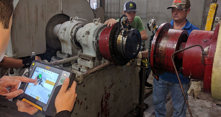
Let us review this case study on a common issue when working on a pump and motor alignment done by Brian Franks, Owner and Field Service Technician of JetTech Mechanical.
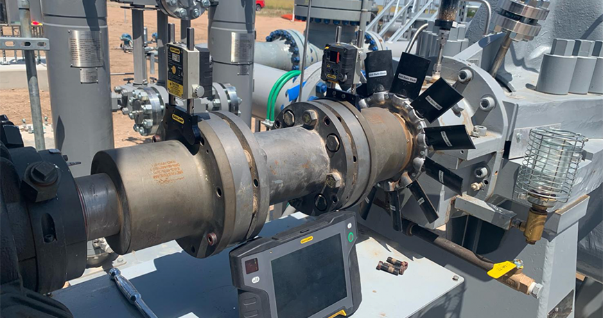
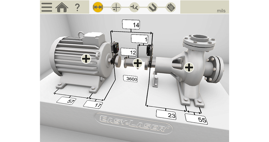
He begins in the normal manner entering the distances of the machine. As you can see this is not a small machine (see Figure 1 below) – there are 57 inches between the motor’s feet and if you add all the measurements together you have 87 inches from the Stationary laser detector unit and the back foot of the movable machine (motor). Notice also that it is a spacer coupling.
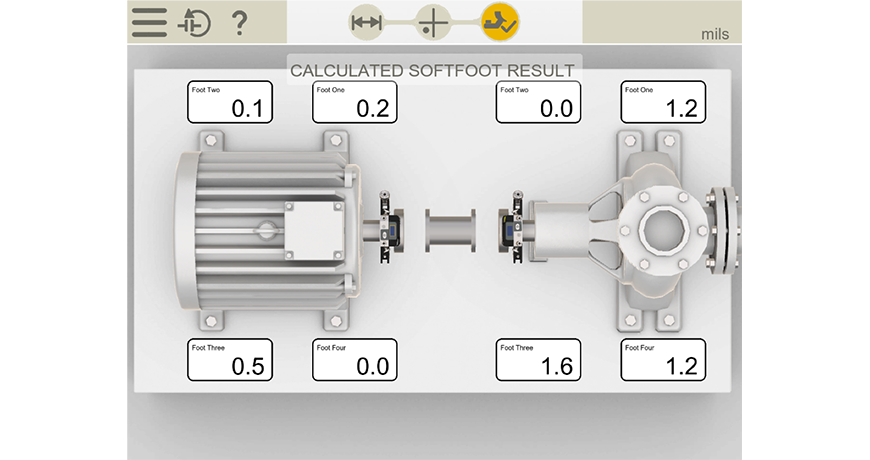
He continues doing the alignment work by taking a soft foot measurement on each of the machines and as you can see, there is very little, so we know it’s a stable base that the machine units are sitting on.
An important note is that they would need the coupling open/loose and the pipe disconnected in order to do this correctly.
The new ANSI standard (ANSI/ASA S2.75-2017/Part 1) allowable soft foot tolerance is two thousandths (0.002 thou or 2.0 mils) of shaft deflection and he is below this, so he is good to go. He documents it for his report.
He now performs the machines’ shaft to shaft alignment.
Notice that he’s removed most of the bolts from the coupling in order to allow the coupling to flex. This is a stiff coupling so you don’t want it locking up during the alignment and you also want to make as few moves as possible. So, this is a good practice. This also tells me they know what they are doing which is good.
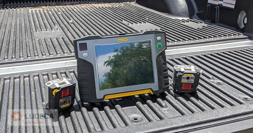
The tool they are using is an Easy-Laser XT770 which is a dot laser system that can read in the horizontal and vertical plane.
Better Running Conditions from Precision Alignment
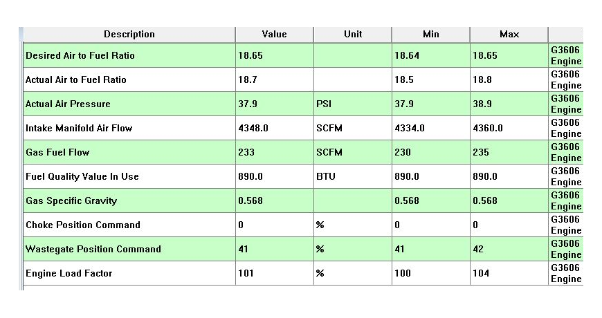
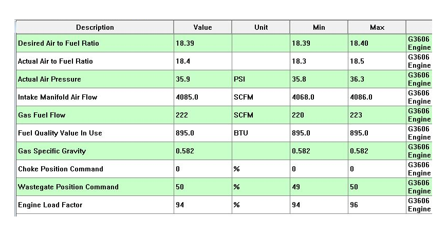
We performed an alignment as part of a yearly check on a Caterpillar G3606 engine mated to an Ariel JG-D compressor. Documentation was established to track the performance of the equipment before and after the alignment.
Before alignment:
The engine was running overloaded, consuming more fuel than budgeted, and over the permitted emissions levels. Initial readings found 0.012” of misalignment, and soft foot of 0.005” in a single mounting pad. Correcting the alignment to within 0.004″, using thermal growth targets, and correcting the soft foot, yielded the results needed for better running conditions.
After alignment:Load was reduced by 6%, and fuel flow dropped by 10 cfm (saving $8800 per quarter). Emissions were well within permitted levels. This mitigated the possibility of a fine, which could be up to $33,750 PER DAY of non-compliance. All of these realized gains resulted directly from a precision laser alignment, carried out with precision tools, performed by properly trained technicians, to the standard of excellence required in today’s cost-aware environment.
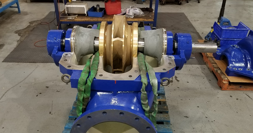
Our colleges at Benchmark PDM recently had a request from a customer to do some pump alignment. When we normally think about pump alignment, we usually think of shaft to shaft alignment. In this case, they wanted bore alignment. They were installing a brand-new pump and when they rotated the shaft, they could hear grinding.
After further inspection one of the techs could see that the bearing housing had been moved – either during shipment or when it was stored. They could see that the dowel pin had been damaged.
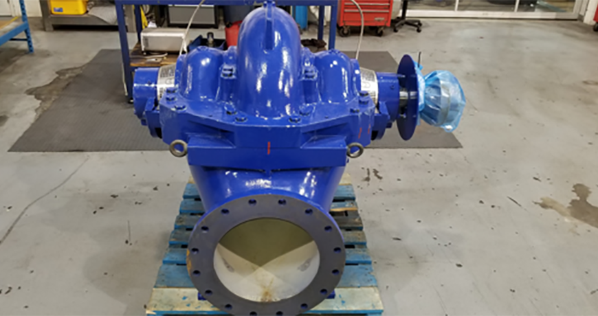
Figure 1
If you pop the lid off this style of pump (See Figure 1 – photo courtesy of KSB Pumps Canada), we see the shaft and the center mounted impeller. On each side of the impeller we have the wear rings, which sit in the bores. Outside of that we have two stuffing boxes or seal bores and outside of these we have the bearing Journals which are also bores. All of these bore centers need to be colinear, meaning in a straight line.
The old traditional methods for doing this type of work was done using piano wire or a mandrel. They would use the stuffing box or the wearing bores as reference points then measure to see if the bearing bores where in alignment. This method was “hit and miss” because its so difficult to set up and measure in this way. It also took a very long time.
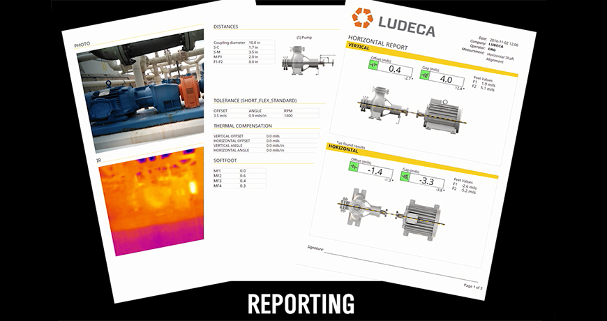
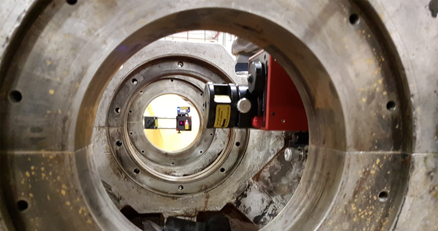
Bore Alignment with Lasers
Using a laser-based measurement system has significantly reduced the time taken to do bore alignment. More importantly, it has improved the accuracy significantly. There are now automatic reports that go with the final bore alignment that has been completed – a documented history of the work is very important.
Figure 2
There are many different applications where bore alignment is done using lasers. For example, extruder barrels that need to be aligned to a gearbox in the plastic industry, crankshaft bearing journal bores in diesel/natural gas engines or compressors in the oil & gas and energy industries and stern tube alignment in the shipping industry. These are just three examples that show how varied the type of alignment work is.
You’ve always heard the adage, “S” Laser on the Stationary and “M” Laser on the Movable.” In this day and age, however, this “truism” has almost become obsolete. You see, the concept of the “stationary” machine, per se, is obsolete. ALL machines CAN be moved if they really need to be (no machine grew out of the ground, like a tree!), so instead we emphasize that the “S” laser should be mounted on the machine that is “more difficult” to move (usually the pump because of the connected piping.)
The flexibility that all Easy-Laser XT-Series systems offer through their lock feet function, as well as the ability to freely flip or rotate the view of the machines to suit your needs, means that you no longer need to concern yourself with “stationary” machines. Your real goal is to find the easiest and most expedient way of aligning your machines. In some cases this may mean moving one pair of feet on the pump just a tiny bit to keep from having to move the motor feet a lot. This means you can save yourself from becoming bolt-bound, or base-bound (not enough shims left under the feet to be able to come down.)
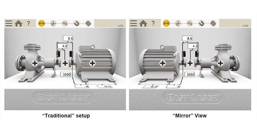
Traditionally, you always try to set up so that your Stationary (or Hard-to Move) machine is on your left, and your Movable machine is to your right. But what if your pump and motor are mounted close beside a wall, and you can only access the machines from one side? As luck and Murphy’s law would have it, that side is always “the wrong side”, with your pump on the right and the motor on the left, instead of the way you are used to seeing them. No matter! Still mount your “S” laser on the pump. Now, since the Easy-Laser XT system wants to move the right machine by default, you can now employ the “Mirror” feature, which will automatically swap the view of your machines left and right, so you can see them the way they really are in the field, and easily move the left machine instead.
If you have two equally hard-to-move machines, each of which you would ordinarily like to consider stationary (such as a heavily piped little steam turbine driving a heavily piped compressor), then it really just boils down to which machine (or combination of feet on both machines) is the most expedient to move. Just mount the “S” laser on the on the left as usual. You can always use the lock feet function to declare the machine on the right stationary and make the machine on the left movable, or ask the tool to make any combination of feet movable so as to find your smallest possible moves or optimal combination of moves to solve bolt-bound or base-bound situations in the field. The Easy-Laser XT products are especially versatile for this, since they let you explore fully optimized centerlines (move ALL the feet in the train), as well as under-constrained and over-constrained centerlines, to cope with the exigencies of the situations you encounter in the field.
Lastly, if you ever need to compare your alignment or your target specs to a drawing or to someone else’s report that shows the machines the other way around from the way you set up, you can always use the Mirror functionality to look at your results from the other side. You use this feature “after the fact”—in other words, after your setup is already complete, with readings taken and results obtained, you can still always rotate the view and see your results as if you had walked around to the other side of the machines.
To summarize, the concept of “Stationary” and “Movable” is history. Use the Mirror feature right at the beginning, when you set up, to make your setup conform to your actual situation in the field. Use the Lock Feet Function to make any machine movable or stationary, and to explore “best possible” correction alternatives. Lastly, you can also use the Mirror feature to look at your alignment differently, after it’s already done.
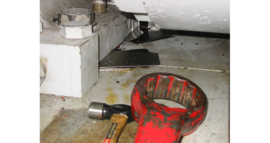
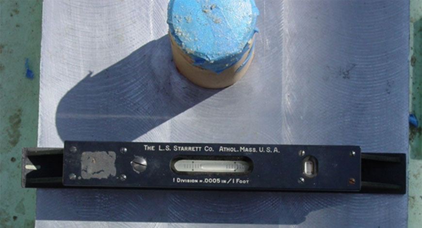
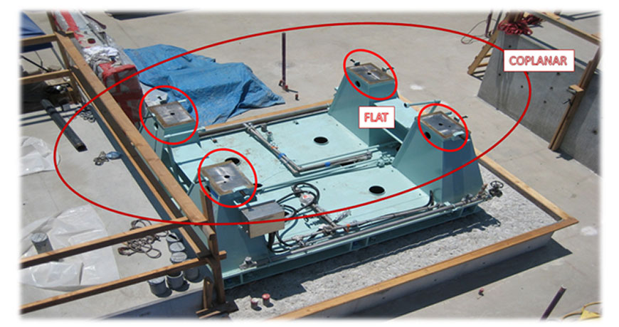
Baseplate tolerances, such as cited in ANSI/ASA Alignment S2.75-2017, specify that a baseplate must be level to <10 mils/ft, coplanar to <2 mils and each foot must be flat to <5mils. The machinist precision level is typically specified to be 0.5 mils per 12”. Automatically, it is assumed that this is sufficient for baseplate installation because the 0.5” per 12” is of a higher resolution than the tolerance.
If you had a granite surface plate, then the machinist level would absolutely work as the entire surface is dead flat and coplanar. You can place the level at any point of the granite surface and assuming that you keep the same orientation, you will get identical bubble readings on the bubble level.
Unfortunately, baseplates are not entirely flat. Depending on where you place the machinist level, you will get entirely different readings. The warp on the baseplate gets magnified by the mounting points, methods of attachment and the weight of the baseplate causing warp from gravity.
Fortunately, there is a field-proven solution to make sure the baseplate is flat and level. The Easy-Laser XT770G, the complete rotating equipment alignment commissioning package, includes the D22 rotating laser.
The laser projects a perfect 263-foot laser plane with a detector that has 0.1 mils resolution. This is far greater than the 12” range of the machinist level. In general, this allows the base to be leveled to 0.02 mils/” and coplanar to under 0.5 mils. Machinist levels can’t ensure that surfaces are coplanar, as shown in the photo below:
A laser works like a high precision straight edge, allowing for such surfaces to be measured all at once.
In the same way it has made shaft alignment easy and accurate, flatness and level measurements can also be taken by the same installation crew prior to alignment. The measurements can be taken, flatness corrected and documented using the same computer that will be used for the shaft alignment task.
Our Easy-Laser XT Series is the only laser alignment platform on the market today with the new ANSI alignment tolerances built-in giving the user the freedom to choose between traditional tolerances, the new ANSI standards, or custom tolerances.
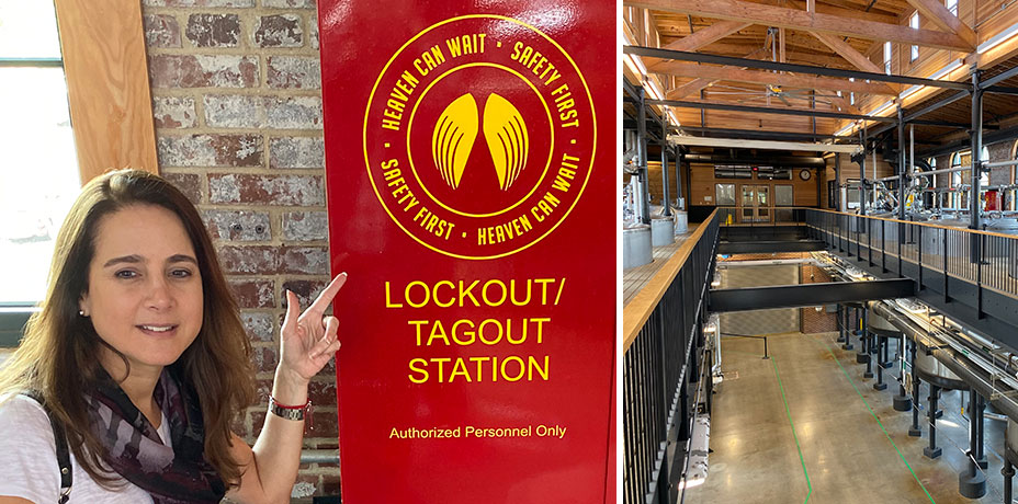
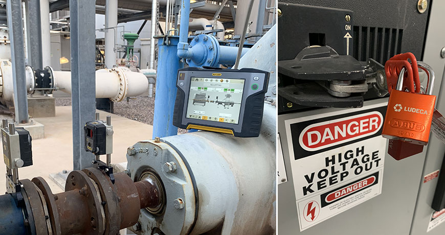
While in Louisville, KY after the #SMRP19 conference, I took a tour of the Angel’s Envy bourbon distillery and was thrilled not only by their fine bourbon finished in port wine barrels but by their attention to safety and unique promotion of safety all around their clean facility. Their clever “Heaven can wait. Safety first” statement obviously applies to all maintenance activities but in this particular case, shown in my photo, it was used to emphasize the importance of lock-out and tag-out procedures, also known throughout our industry as LOTO.
Unlike ultrasound testing, acoustic lubrication or vibration analysis, all of which check machine or facilities condition while up and running, alignment and balancing require machines to be shut down and properly locked out, to adhere to all safety regulations. Only then can the components be mounted on the shafts. This ensures the safe rotation of the shafts and alignment corrections to be made without risk of injury to maintenance personnel.
I can’t stress enough the importance of safety during service or maintenance of machines and encourage you to develop more ingenious slogans like “Heaven can wait. Safety first” to draw more attention to this important concern within your plant.
Here are the six steps to follow for proper LOTO per OSHA 3120:
1. Prepare for shutdown;
2. Shut down the machine;
3. Disconnect or isolate the machine from the energy source(s);
4. Apply the lockout or tag-out device(s) to the energy-isolating device(s);
5. Release, restrain, or otherwise render safe all potential hazardous stored or residual energy. If a possibility exists for reaccumulation of hazardous energy, regularly verify during the service and maintenance that such energy has not reaccumulated to hazardous levels; and,
6. Verify the isolation and deenergization of the machine.
A personal note for Bourbon lovers: if you haven’t already, try pairing dark orange chocolate with your favorite bourbon, what a delicious combination! Heaven can wait. Please drink responsibly.
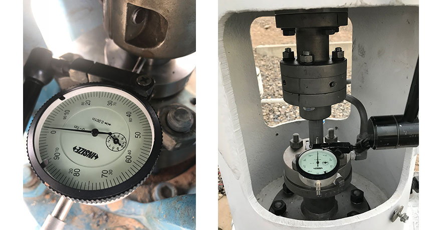
Before precision alignment is to be performed on rotating equipment, best practice dictates that there are a few things that should be checked, even before doing rough alignment.
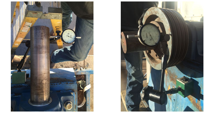
One of those things is checking coupling and/or shaft runout. Runout is a condition where the centerline of the coupling or shaft has deviated from its true axis of rotation. To measure coupling or shaft runout, it is common to use a dial indicator with a standard magnetic base. Simply mount the magnetic base on a stationary surface. Then mount the dial indicator on the surface to be checked. For example, if checking radial runout on the coupling, we would place the dial indicator on the outer diameter of the coupling. We proceed by rotating the shaft of the machine and observing the face of the dial, looking for movement of the needle. This might tell us that the coupling was not bored concentric to the shaft centerline. If excessive runout is found on the coupling, it is good practice to check runout on the shaft as well. If there is also excessive runout on the shaft, this could mean that the runout at the coupling could be due to a bent shaft. At this point, and depending on the severity of the shaft runout, the shaft of the rotating machine may need to be replaced.
In some instances, it is also a good practice to check the axial runout on the coupling. This means we would place the dial indicator on the outer face of the coupling hub and look for movement of the dial. Excessive runout, in this case, would mean that either the inner diameter of the coupling hub was not bored concentric to its true centerline, or the coupling hub was not installed properly onto the shaft (i.e. when a dead-blow hammer is used to mount the coupling hub). Essentially, the axial runout of the coupling suggests that the coupling hub has an angle, in comparison to the shaft. It is very likely that you will find runout on almost every rotating machine that you measure. However, just like for precision alignment, we have allowable tolerances for runout. Typically, the maximum allowable amount for runout is 0.002″ (2 mils or thou). In the case of a higher RPM machine (more than 3600 RPM), a tolerance of 0.001″ (1 mil or thou) should be used. Although some people have thought that checking runout is a waste of time, it certainly is not. It confirms that the coupling was manufactured and installed correctly and that the shaft is not bent.
When you are installing a new machinery in a facility of the organization, there are certain issues. These issues are listed from top to the bottom categorized on the basis of seriousness. The top of the list is shaft alignment. It is the most common issue while installing the machinery. It occurs due to lack of training or of precision instruments, as well as measurement misconceptions. Most organizations think they have achieved alignment just because an instrument showed so. They don’t take the stress and heating mechanisms into account which causes misalignment between the colinear wings of the shaft.
The second issue is the measurement in the base. The machinery installation should start with the removal of stress. The best place to start doing this is by making sure the base is level and flat. You can’t just use any off the shelf leveling tool for that. You need to stick to the height and level measurements from the surface. The third issue is soft-foot. It occurs when one foot of the machine is not in level with the other one. It can cause distortion in the machine casing. It also affects alignment measurements when you are checking for correctness. Download our Soft Foot: Causes, Characteristics and Solutions for the in depth causes and characteristics of soft foot conditions and how to diagnose and solve them
Then comes the pipe strain that causes shaft deflection and case distortion that leads to pump failure. So, you need to avoid putting stress on the pipe. The next one on the list is offline to running. It occurs because of thermal growth in the machine. You can change operating temperature for reducing the initial start-up tork. But there will still be some amount of tork that can lead to this issue. The sixth issue is coupling run-out and machine looseness. It causes vibration in the machine just like misalignment. You can find it out using a dial indicator. You should look for the run-out in coupling and also check the bearings. Watch our Shaft Alignment Know-How video to learn about the effects of running equipment with pipe stress
The number seven is moving the machine. You need to have control when you are moving a machine to avoid sliding. You can use jacking-bolts for that but you need to check the integrity of the bolts as well. You can use the laser to fix this issue or by using graph paper to show how to optimize the machine movement. The next issue is hardware because it makes a lot of difference. Use of poor hardware like nuts, bolts, and key chains can cause machinery issues too. You also need to use proper tools while tightening the bolts and make sure they are calibrated right for the job.
All of this depends on the training because they need to be able to use all the necessary tools. They need to have the proper training. They should be able to do more than just pushing the right buttons. They need to be guided about the proper machinery installation. They should be trained at a standard level for this. The last but not the least thing is to have proper documentation of the quality measures that are taken because it helps you understand the operational phase of the machine.
Thank you James Kovacevic with Eruditio LLC for sharing this [podcast] with us and John Lambert with BENCHMARK PDM for his excellent knowledge on machinery installation!
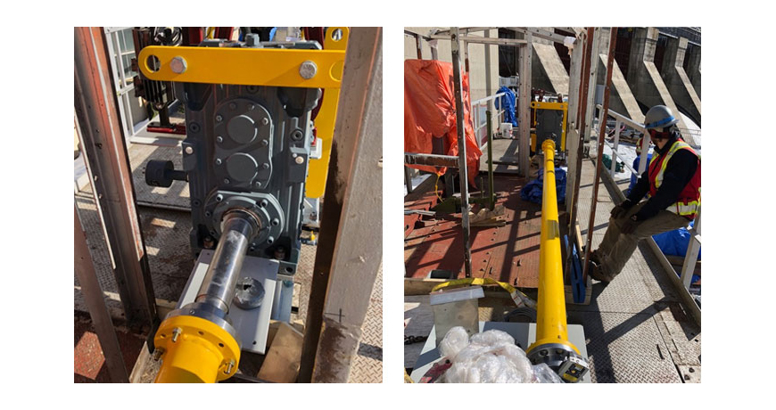
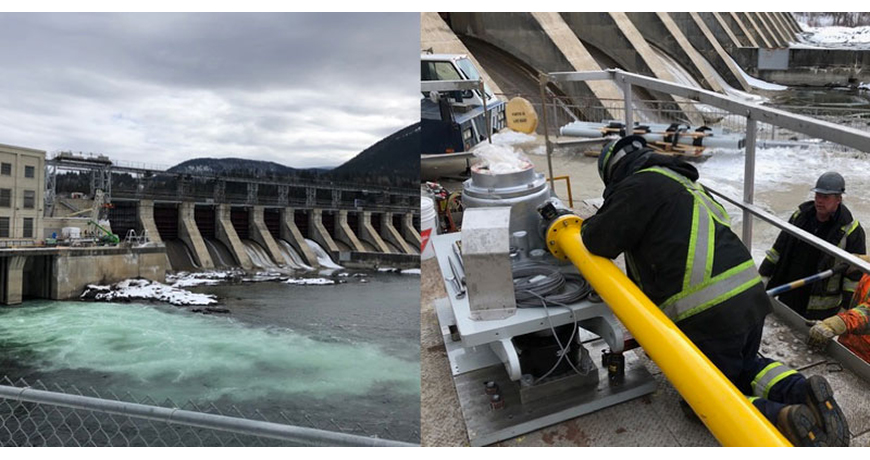
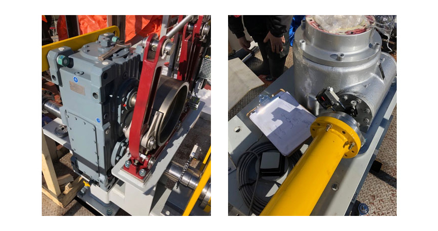
When you are working with nature, you treat it with respect. And that’s what this dam facility on the Kootenay River in British Columbia does (image, above left). When you harness the power of a river you need your control systems to work. The spillway gates control the level of the dam and in this example, it is lifted and lowered by two Worm Drives that are approximately 33 feet apart, so it’s a large gate. Pictured (above right) is one of the worm drives.
The drive motor and gearbox are mounted in the middle and the complete system is being replaced. As with any machinery installation work there will be a lot of alignment work required, including the two drive shafts which are 176 inches in length.
Chad Hansen of CH Mechanical was asked to do the shaft alignment work on the complete drive. Chad owns an EASY LASER XT660 shaft alignment tool which can cover a measurement distance of over 66 feet. He is confident he can do this work however, as the largest span from worm drive to worm drive is 33 feet. But the work doesn’t start on site, it starts back in the shop.
Aligning the Drive Assembly
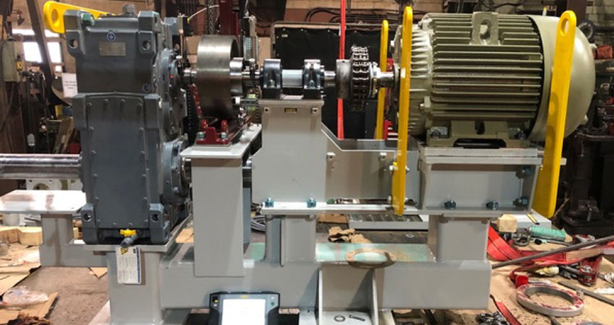
This is the drive assembly (image below) for the two jackshafts that drive the worm drives, which opens/closes the gate. A new base had been fabricated, which in its self is a nice piece of work! Notice that it has four different levels with machine components attached. That’s 8 mounting foot pads, one for each mounting bolt. Each of these mounting surfaces should be flat. Each set of mounting pads should also be coplanar; for example, the four foot pads for the motor should be flat. I could go on about the importance of base flatness but i’ll leave that for another post!)
Now let’s look at the machine’s components. A good-sized motor with standard mounting feet has a shaft coupled with a chain coupling. This connects to the short spacer shaft supported by two pillow block bearings. This is coupled with a flange-mounted rigid coupling which then connects to a drum brake that is mounted on the gearbox input shaft. Now for the gearbox. The one output shaft is obvious, coming out of the front side of the gearbox (left side of image) with the shaft parallel to the motor shaft. The other shaft is harder to see, on the opposite side, under the drum brake pedestal running underneath the motor. The motor and pillow block base will be removed during the installation but this pre-assemble is to make sure it all fits without being bolt-bound or base-bound.
The most important aspect of this machine’s installation is mounting the gearbox and setting the brake, and that where Chad starts. The gearbox input shaft must be parallel with the mounting surface of the brake. This can be achieved by shimming the gearbox and/or the brake. It’s usually a combination of both to get the optimum move but its time well spent. The end goal is that there is no gearbox shaft deflection when the brake is applied. This means no angle or offset. Next, the spacer shaft is aligned to the gearbox shaft. This is a rigid coupling, so it is best to do this with the coupling open (separated). This is done by using the two built-in electronic inclinometers in the measuring units and either the 9-12-3 measurement method or EasyTurn measurement method. Either way you get a high accuracy, repeatable alignment.
After this you can align the motor to the spacer shaft. With the Easy-Laser XT660 Shaft Alignment tool Chad has different measurement method options because this alignment work is important. Here, he can use the multipoint measurement method and take a series of measurements. He can align the motor to the spacer shaft then go over the top to align the motor to the gearbox shaft, his choice. He can use the new ANSI standard tolerances which is in the display and will be shown in the report.
Installing the Drive Assembly and Aligning the Jackshafts
The whole gearbox and drive assembly are installed on site. However, the bearing pedestal, motor, and motor base has been removed for easy access (image, below left).
The right-side jackshaft is installed first, that’s the one closest to the dam. You can see the moveable laser/detector unit mounted on the output shaft just below the drum brake. The worm drive (image, above right) will be the stationary machine with the other laser/detector mounted. The laser alignment data is collected using EASY-LASER’s EasyTurn measurement method with the results showing the amount of misalignment and in which direction they need to move the machine.
The alignment work is completed. There is a little wiggle room at the worm drives however, most of the corrections are made by moving the drive assembly. CH Mechanical uses the new ANSI alignment tolerance for spacer/jackshafts. They are well within spec so it’s a job well done. The actual numbers remain the property of the Dam, so we won’t publish them. However, there is a lot of margin on a 176-inch shaft length. That’s not to say that it’s a quick job, its not. Its actually a very complex job made easy by Chad Hansen and his EASY-LASER XT660 shaft alignment tool.
Thank you John Lambert with Benchmark PDM for sharing this successful story with us!
I remember once performing an alignment where I followed the guidelines at the time to make sure no soft foot was present before continuing the alignment. I struggled to take care of the soft foot issue, yet still had unacceptable results. No more than 3-5 shims under each foot? Check. Pull each shim pack with all feet unbolted and fill in obvious gaps? Check. Inspect shims and remove rusted, damaged or crinkled shims? Ah –hah!
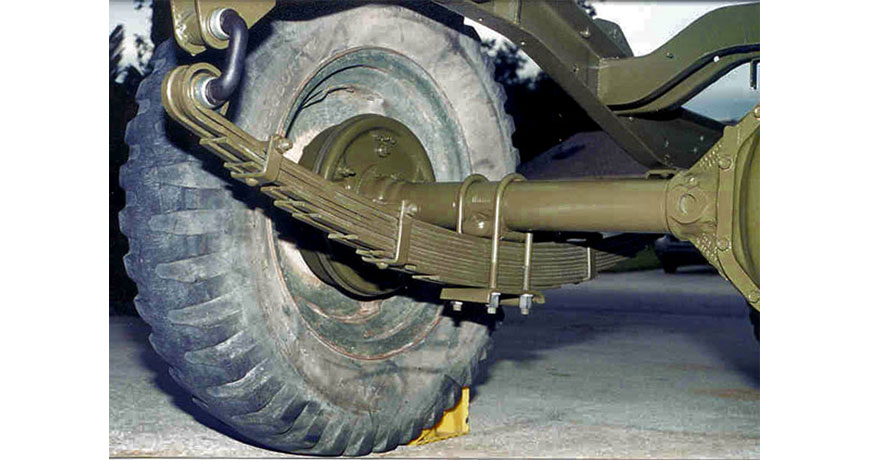
At that point, I inspected the shims and found one, a 150 thou shim, to have a slight bow in it due to it conforming to the base. I essentially had a leaf spring under the foot. No amount of shim corrections will eliminate this situation. A leaf spring is a very common suspension component found in trucks and trailers and shown below.
This leaf spring effect manifests itself in two forms:
The first form is when a very large shim is bent and placed back into the machine foot upside down. This forces the machine foot up when the bolt is loosened during a soft foot check.
The second form is when there are a stack of more than 5 shims, particularly if they are crinkled or bent. The combination of these defects also creates the leaf spring effect.
The importance of pre-alignment checks is important in rotating equipment alignment. It is so important that we have incorporated it as step #1 in our standard Ludeca 5-Step Shaft Alignment Procedure as shown below.
The importance of these pre-alignment corrective actions have been incorporated into the ANSI/ASA S2.75-2017 alignment standard. According to the standard:
Shims should be in clean, smooth condition. Used shims should be discarded if the damage is evident. No more than 5 total shims shall be placed under any machine case foot, excluding the shims to correct angle foot conditions. No more than 1 of those shims shall be less than 0.08 mm (0.003 inches) thickness. The sum of the three thinnest shims shall be 0.25 mm (0.010 inches) or greater.”
Removing the soft foot issues is important and fortunately, there is a field-proven solution to make sure these have resulted in the problem being remedied and documented. All Easy-Laser E-series and the latest XT-series alignment systems, incorporate a soft foot check program.
Using .0001” resolution detectors, the shaft movement observed when loosening and tightening each foot can be documented for soft foot analysis and correction. With soft foot remedied, the alignment can now proceed with peace of mind knowing the corrections will be more precise and that internal frame distortion of the machine is eliminated.
There are many reasons why one would perform an uncoupled alignment. We could have a tight tolerance coupling that cannot be installed without getting the alignment of the shafts close. Or simply, we do not have the coupling available at the moment the alignment needs to happen. Uncoupled alignments are performed using the same 5-step alignment procedure as you would use for coupled alignments. However, there are three differences: how the measurements are taken, how live adjustments are made and how soft foot is checked. Below are some easy-to-follow instructions on how to tackle measurements, live adjustments, and soft foot with Easy-Laser shaft alignment tools:
Alignment Measurement:
Attach measurement unit and brackets to each shaft.
Place the S laser on the stationary machine’s shaft and M laser on the movable machine’s shaft.
Make sure the lasers are at the 12 o’clock position using the lasers’ digital display and the same angle for both S and M lasers are displayed (worst case within 1 degree).
Select the Multipoint measure mode, and take your first point.
Rotate each shaft to the next measurement position of your choosing, making sure the digital display shows the same angle on both S and M lasers (within 1 degree) and take the next point.
Repeat step 5 until the quality of your measurement is above 90%.
Take a second set of measurements to ensure repeatability.
Live Adjustments:
Horizontal live adjustment – rotate the lasers to either the 9 o’clock or 3 o’clock position, making sure the lasers’ digital display shows the same angle for both S and M lasers (within 1 degree).
Vertical it is simply a matter of adding or removing shims. However, to perform a vertical live adjustment rotate the lasers to the 12 o’clock position ensuring the lasers’ digital display shows the same angle for both S and M lasers (within 1 degree).
Go on to the live adjustment screen and perform moves as if the machines were coupled.
Soft Foot Measurement:
After the final alignment measurement, return the lasers to the 12 o’clock position again, ensuring the lasers’ digital display shows the same angle for both S and M laser (within 1 degree).
Access the soft foot measurement screen and check the soft foot as if the machines were coupled.
Watch our 5-Step Shaft Alignment Procedure motion graphic video which outlines an easy and effective way to align your rotating equipment.
We used to assume that once equipment is installed and aligned, it will remain in the same position forever. But this is not always the case.
The alignment should be checked periodically. This valuable information will help you to find problems like pipe stress, unstable foundations, weak frames and loose bolts, among other problems. All the efforts to align your equipment and keep it within tolerance will be worthless if your machinery can’t keep its position. Therefore, the repeatability of the alignment check is your best ally to see how the equipment behaves.
How often should you check?
There are guidelines for how often the alignment should be checked. According to John Piotrowski in his Shaft Alignment Handbook, for newly installed machinery the alignment should be checked after 500 to 2000 hours of intermittent operation, or 1–3 months of continuous operation. If there was no apparent shift in the alignment, then next check should be made at between 4500 and 9000 hours of intermittent operation or 6 months to 1 year of continuous operation. If no apparent shift occurred at any time, then checks should be made every 2–3 years. This interval can of course be influenced by factors such as equipment criticality etc.
If a moderate shift in alignment occurred at any time, then the equipment should be realigned to within acceptable tolerances. If a radical shift occurred, then additional investigation should begin to determine what is causing the shift – a root cause analysis. For example, any indication of excessive wear and tear will also be an indicator of a “non-healthy” machinery installation.
The importance of documentation.
To have properly documented alignment checks is essential to avoid repeating the same installation errors, or to discover and follow up on recurring problems. Of course, there is no exact answer to the headline question. But the documentation will give you a very good understanding of what happens along the way, and help you keep your machinery aligned as long as possible.
Thank you Roman Megela with Easy-Laser for sharing this informative article with us!
We previously discussed the Types of Misalignment and Types of Soft Foot as causes of machine failures. In this blog, we will discuss Pipe Strain and how it can result in misalignment and vibration.
Pipe strain is a form of machine frame distortion caused by the piping as opposed to feet or base condition. The forces from the pipes are transferred through the driven machine onto the driver machine causing vibration and misalignment at the coupling. Sometimes the forces are not great enough to transfer onto the driver, but will affect the internal misalignment of the driven machine and therefore cause premature failure. Here are a few causes of pipe strain:
A shift in the foundation
Incorrect pipe fitting
Thermal expansion of the pipes
Broken, improper, or lack of hangers and wall mounting hardware
Checking and correcting pipe strain in all alignment jobs will eliminate these forces allowing the machines to run properly.
Watch our Shaft Alignment Know-How video to learn about the effects of running equipment with pipe stress


 Load was reduced by 6%, and fuel flow dropped by 10 cfm (saving $8800 per quarter). Emissions were well within permitted levels. This mitigated the possibility of a fine, which could be up to $33,750 PER DAY of non-compliance. All of these realized gains resulted directly from a
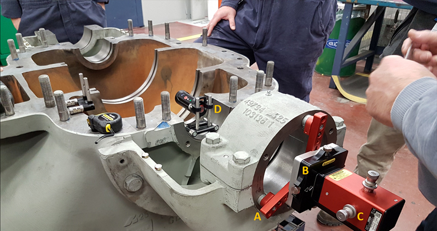


 If you have two equally hard-to-move machines, each of which you would ordinarily like to consider stationary (such as a heavily piped little steam turbine driving a heavily piped compressor), then it really just boils down to which machine (or combination of feet on both machines) is the most expedient to move. Just mount the “S” laser on the on the left as usual. You can always use the lock feet function to declare the machine on the right stationary and make the machine on the left movable, or ask the tool to make any combination of feet movable so as to find your smallest possible moves or optimal combination of moves to solve bolt-bound or base-bound situations in the field. The Easy-Laser XT products are especially versatile for this, since they let you explore fully optimized centerlines (move ALL the feet in the train), as well as under-constrained and over-constrained centerlines, to cope with the exigencies of the situations you encounter in the field.
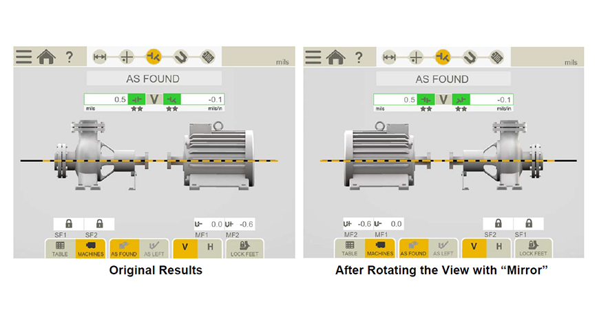


 The right-side jackshaft is installed first, that’s the one closest to the dam. You can see the moveable laser/detector unit mounted on the output shaft just below the drum brake. The worm drive (image, above right) will be the stationary machine with the other laser/detector mounted. The laser alignment data is collected using EASY-LASER’s EasyTurn measurement method with the results showing the amount of misalignment and in which direction they need to move the machine.