
As a Technical Trainer for Ludeca, I teach the importance of following our 5-Step Shaft Alignment Procedure. As Millwright, I have completed many precision shaft alignments over the last 28 years of my career. In this time I have witnessed many other Millwrights and Technicians forget to do a thorough visual inspection of the foundation, grout, and baseplate before attempting the alignment. Following a procedure and ensuring that every section of it is done will help you achieve precision results in your shaft alignments, and get it done much faster.
Foundation
The foundation should be of adequate size and in good condition. A rule of thumb calls for concrete weight to equal at least three times machine weight for rotating machines, and five times that of reciprocating machines. Can you spot the good and the bad in the following pictures?

Grout
A grout base should be made of suitable material, in good condition, with no voids beneath the baseplate. If recently poured, proper cure time for both the foundation and the grout is important. Inspect the grout. What do you see?
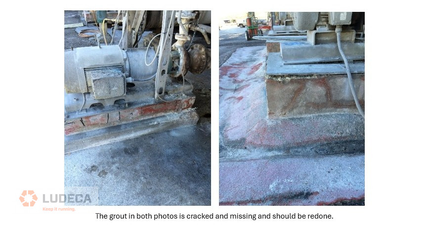
Baseplate
The baseplate must be rigid so that no part of any machine foot moves more than 0.001” out of plane with the other feet of the same machine. Machine mounting pads must be level, flat, parallel, coplanar, and clean. What do you see in the following examples?

Download our 5 Elements Machine Installation infographic for an outline of 5 important elements of machine installation including Foundation, Anchoring, Isolation, Baseplate Level and Flat plus Alignment!
You’ve got it! Why not use it? Taking advantage of visual inspections.
by Diana Pereda
After more than 20 years in the industry, Peter Edström knows exactly what it takes to keep a sawmill running optimally. And with laser alignment, he’s making a real difference.
Peter Edström has been working with Swedish sawmills since 2000 and knows what’s required to create an efficient production line. Over the years, he has helped many customers overcome challenges related to machine settings and alignment. When Wood Control Technology was founded in 2021, Peter became one of the first employees – bringing with him decades of valuable experience into the young company.
Initially, the company focused entirely on selling control systems to sawmills, planing mills, paint shops and other segments of the wood processing industry. But before long, Peter began receiving calls from old contacts asking for help with mechanical issues. That was the start of a new business direction.
“When several of my former customers reached out for help with alignment problems, we decided to expand our services to include mechanical support,” says Peter.
Today, there are two people working with alignment and technical support – and demand just keeps growing.
Small errors, big consequences
A constant challenge for sawmills is maximizing lumber yield and cutting each board to the correct dimensions. To do this, they rely on advanced 3D optimization systems that calculate the most efficient way to saw each log.
“And those systems work,” Peter says. “But how much sawn lumber actually ends up in the yard? The optimization program might say we should get a certain volume, but when we look outside, it’s less. That’s because the sawing isn’t centered, and safety margins are added to account for minor wobbling. So the machines aren’t positioned exactly as the system expects, which leads to lower yield and less lumber in the end.”
Achieving optimal results requires precise machine alignment. And that’s where laser technology, combined with the expertise of companies like Wood Control Technology, makes a big difference.
From problem to solution
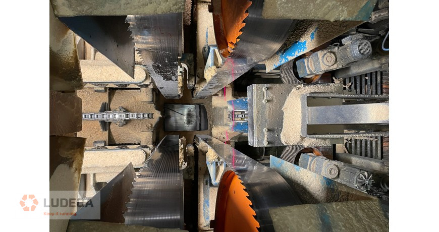
When a sawmill calls for help, Peter and his colleague head out to inspect the saw line. A typical line includes an infeed section that centers the log, a canter, four band saws, and an outfeed section that separates and transports the cut lumber. It’s common for issues to arise already at the log feed stage, such as log rotation or feed errors, meaning the log isn’t properly centered.
“We usually say that a 1 mm feed error in an otherwise standard sawmill can reduce yield by 1%. And 1% less yield means roughly $100,000 USD annually. So it’s a lot of money. And 1 mm is really not much for this industry.”
It typically takes two people about two days to align an entire saw group in a saw line, which fits perfectly into a weekend when production is paused. The cost? Often less than what just one hour of downtime would cost in lost revenue.
The importance of preventive maintenance
Peter sees a clear connection between regular alignment and financial health in a sawmill. It’s all about staying ahead of problems. Many sawmills are proactive and include alignment in their preventive maintenance routines, but far from all.
“Sawmills are good at fixing things. Some go a step further and use preventive maintenance, including mechanical inspections. That way, you catch the issues before they cause a breakdown. But overall, the industry still tends to wait until something breaks,” he explains. “It’s often a matter of cost. They cut back on things that aren’t immediately visible, like mechanical adjustments or lubrication. But those savings come back to bite you.”
“Mechanical settings don’t stay perfect over time, either. Parts get replaced, which can throw off the centering or cause looseness.”
Machines should ideally be aligned at least twice a year, or even four times if production volumes are high. But in practice, it happens far too rarely, Peter says. Many wait until quality issues become unavoidable or customer complaints start rolling in. By then, the financial losses are already significant.
Laser technology makes a difference
When Peter started working in the early 2000s, laser technology was still quite uncommon.
“At first, people were skeptical. They were used to wires and rulers, and optical tooling like theodolites were common. But now everyone wants laser,” he says.
He explains how much quicker and easier it is to set up a laser system compared to older methods.
“You set up the system, then do a rough alignment. You can follow the laser beam along the chains, it’s much faster than using a wire. And the results are more accurate.”
Peter has been using Easy-Laser systems since the beginning of his career and has even contributed ideas for the various fixtures included in the sawmill alignment system. A long-standing, close collaboration.
“I’ve used these systems for so many years, and they’ve come a long way. Even though the software and hardware evolve, like today’s XT980 sawmill system, it still feels familiar,” he says, adding:
“They’re stable, reliable systems with incredible repeatability. And they’re easy and intuitive to use. I love that it’s wireless. You can sit in different places and still see the live values. You don’t have to be inside the machine.”
The right setup maximizes yield
For Peter, it’s all about giving sawmills the best possible conditions for success, from the first log to the final board.
“Every sawmill would benefit from increasing yield, improving cut dimension control, and enhancing quality,” Peter concludes.
Thank you Easy-Laser for sharing this article about Peter Edström’s knowledge of alignment with us!
What is Machine Train Alignment and how important is it? Part 1
by Diana Pereda
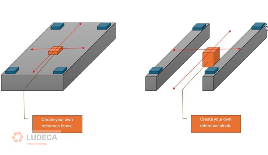
How many times have you replaced a motor and made sure you put the same shims back to ensure the new motor goes back in the same place as the old one? But doing so may end up bringing the issues that caused the old motor to fail to the new one. There is a better way to do things. The Easy-Laser XT550, XT660, & XT770 laser shaft alignment systems can help you make sure you don’t perpetuate an existing misalignment or soft foot problem over and over. Included with the system you also get an app called “Twist” which can help you determine if your base is flat. If you find it’s not, it will tell you what you can do to improve it. While the motor is off the base, create a common point or reference block in the middle of the base. The block can be made by the machine shop in-house and needs to have a top surface of 2 square inches to hold the measuring unit. See Figure 1 below:
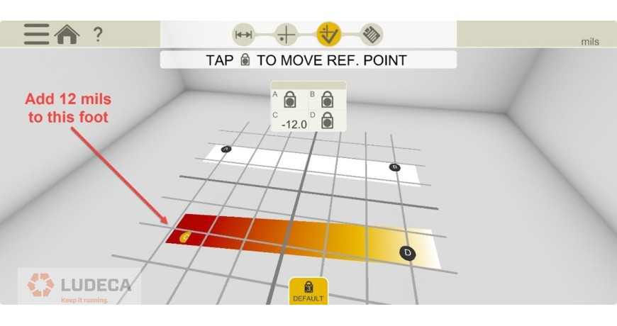
Once the measurement is complete, the Twist app will tell you which machine foot is off plane or not flat and it will tell you how many shims to add under the foot to compensate, see Figure 2 below.
Download our Flatness vs. Levelness using a laser to measure the two infographic for a reference guide to the concepts of flatness and levelness!
by Diana Pereda
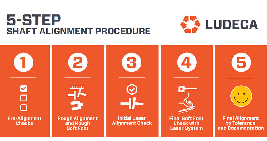
Companies throughout America and the world use the Easy-Laser alignment systems as well as other laser systems for precision alignment. Ludeca has made it “easy and reliable” to perform precision alignment with a simple 5-Step Shaft Alignment Procedure that is easy to follow and accessible on Ludeca’s website in the Knowledge Center. Being a technical trainer for Ludeca, I always use this 5-Step Shaft Alignment Procedure in every training session!
This simple but straightforward guide will ensure that the mechanic, technician or millwright performing the alignment has a set procedure to follow “every time” an alignment is done. Using the Ludeca 5-Step shaft alignment procedure builds consistency into the alignment process for greater success.
It is very important when doing precision alignment that everyone is on the “same page!” So if you are a maintenance or reliability manager who has the responsibility of overseeing and ensuring that precision alignments are done correctly and done right the first time and you do not currently have a standard operating procedure (SOP) or an alignment procedure built into your best practices for your facility, then please consider implementing this at your workplace or at least drawing from this great resource. It takes your mechanics and millwrights step-by-step through a procedure that has proven itself time after time.
From Lock Out Tag Out all the way through final alignment documentation, Ludeca and Easy-Laser make it easy and reliable for you to Keep it Running!
What Machine Components Benefit from Precision Shaft Alignment?
by Diana Pereda

Chain drives are widely used in industrial settings throughout the world. Knowing the advantages and disadvantages of chain drives and how to properly maintain them can help you to keep them running as intended. Chain drives consist of a series of chain links which mesh with toothed sprockets. Chain Sprockets are locked on the shafts of the driving and driven machinery. Chain drives provide a positive form of power transmission. The links of the chain mesh with teeth of the sprockets and this action maintains a positive speed ratio between the driver and driven sprockets.
Chain Drive Advantages:
- Chain drives, unlike belt drives, do not slip or creep.
- There is no power loss due to slippage. This makes them more efficient than belt drives.
- Chain drives are more compact than belt drives.
- Chain drives are a better choice for slow speed drives.
- Chains can operate effectively at high temperatures.
- Chains do not deteriorate due to oil, grease, exposure to sunlight or age.
- Chains typically withstand chemicals and abrasive conditions better than belts in belt drives.
- Chains can operate in wet conditions.
- Chain drives are effective when several shafts are to be driven from a single shaft, as precise timing between the driven shafts is usually required.
- Chain stretch, due to normal wear, is a slow process.
- Chains require less take-up adjustment than belts.
Chain drive Disadvantages:
- Chains cannot be used where the drive must slip.
- Chain drives cannot accept much misalignment.
- Chain drives need frequent lubrication.
- Chain drives are noisy and can cause vibration.
- Chain drives do not have the load capacities of gear drives.
Download our 5-Step Sprocket Alignment Procedure – a simple and effective procedure for sprocket alignment of chain-driven equipment!
Align Your Belt or Chain-Driven Machines with Modern Laser Belt Alignment Systems!
by Diana Pereda
When a new technician enters their field of employment, the normal procedure for training is to send them out with older techs that have been doing the job for a while. This is a good old fashioned OJT (On The Job Training). The goal is to have the new tech up to speed quickly, and self sufficient to the point that they can be trusted to work on their own. Maybe, if they pan out, they can be sent later for formal training. Or, at least tested to achieve a certain level of certification. While they are learning the basics for operations and maintenance for their equipment, they will also be told to memorize certain numbers for the adjustments and settings for that same equipment. And this is where the problems start creeping in. Some of those numbers are being given as the specifications, with little to no understanding of how and why those numbers exist. Let’s look at alignment specifications, since that is what Ludeca deals with the most.
I am going to work with natural gas compression, since that is the industry where I have the most experience. The numbers that are always being tossed around are “5 & 5”, as in .005″ for offset and .005″ for angularity. I call that a classic field spec, not a true specification. There are so many things that those numbers do not address.

Here are a few of those things:
- How much thermal growth does each component have for this particular alignment? There are several different engine makes and compressor brands, which all have different models having different growth signatures.
- For instance, an Ariel JGK compressor is advertised by the manufacturer to grow .011″. And some of those can be coupled to a Caterpillar 3400 series engine, which is advertised to grow .015″. With this pairing, the engine would need to be left .004″ lower to compensate for that growth. Some compressors in that same size frame group can be coupled to a Caterpillar 3500 series engine, which grows .019″. That means the engine would actually need to be .008″ lower than the compressor when everything is cold, so that it will be in the correct position when the engine and compressor achieve full thermal growth.
- What is the Diameter of the coupling? While this has nothing to do with the tolerances, it changes everything if you are using the coupling diameter to reference a gap difference against. This comes from the old equation for correcting angularity when using dial indicators. AB/CD where AB is overall length of the movable component divided by the coupling diameter. And if you really worked it out, .005″ TIR on a 36″ coupling was much tighter than on an 8″ coupling. It makes it look like the entire industry was working on a sliding scale of accuracy, and when I asked about it, I was told that it didn’t matter as much on the smaller ones, because they are “cheap”.
- What is the rated speed of the equipment? Speed dictates the tolerances, plain and simple. Think of an engine built 60 years ago. To rev one up above, say, 5000 RPM would scare a lot of people. They would be sure that it would just come apart running that fast! Engines today rev much higher, with no thought being given to those extra few thousand RPMs. It has everything to do with the tolerances during the design and assembly process for the newer engines. We can run them faster because of the tighter specifications. Alignment is the same way. If a traditional Gas Compressor Tech tries to align a gas turbine the same way they would align an engine-driven compressor, it would be a short run and a long (and costly) repair.

And I know a lot of people will say, “but the coupling manufacturer’s specifications say that they can accommodate so much misalignment”. Yes, the specifications do indicate that a certain amount of misalignment can be tolerated, but only for intermittent lengths of time, like a cold start up, to allow the machines to “grow into alignment” with each other as they warm up and are put under load. The flex in a flexible coupling is normally to allow the machinery to run for a while, until full thermal growth and load is achieved which hopefully has everything in correct alignment. Much more important is to look at the internals of the equipment. How much misalignment can those parts withstand for extended periods of time? Certainly, much less than the coupling is built to take.
These were just a few of the things to consider when discussing tolerances and specifications. I was very careful to call the field numbers “Specs”, not specifications. Some of the specs given are just too arbitrary for the level of safety and operational efficiency needed for this type of equipment. Knowing the actual specifications, and even the reasons for them, is too important to ignore. With a little effort, using dealer contacts, available documentation, and a good search engine, correct Specifications can be found.
A Before and After of Alignment on a Caterpillar Engine mated to an Ariel Compressor
by Diana Pereda
In mechanical design, one of the core principles I learned is that “everything is a spring.” This concept underscores that all materials under stress behave like springs, which has profound implications for machinery installation and maintenance. Machines and the bases they sit on may seem to be perfectly rigid, but when the alignment tolerances required are at the nearest thousandths of an inch (0.02mm), more variables will need to be introduced.
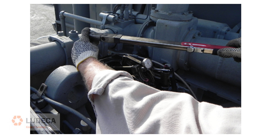
A prime example is the use of torque wrenches, essential tools for ensuring precision. When installing components like a car engine’s valve cover, uneven torque application can distort the component, leading to gasket failures, leaks, or even structural breakdowns. This principle also applies to aligning rotating machinery, where even the slightest internal misalignment (referred to as “soft foot”) can distort machine frames.
The ANSI-ASA 2.75 shaft alignment standard specifies that soft foot should not exceed 2.0 mils (0.04 mm) per foot for optimal performance.
Torque wrenches play a critical role by providing consistent torque application, which is vital for making precise adjustments during alignment processes. This consistency eliminates variations in torque application that might occur with different operators or tools, simplifying what can be a challenging alignment task. Resources like Ludeca’s free Soft Foot Find-and-Fix Infographic offer practical guidance on this issue.
Moreover, understanding the nuances of torque application – whether it’s wet or dry (with or without lubricants) – is crucial for safety and functionality. Wet torque reduces friction; hence less torque is needed compared to dry scenarios where friction is higher. For detailed guidance, resources like the Machinery’s Handbook – Industrial Press are invaluable in any maintenance setting, providing standards and best practices for torque application.
In essence, recognizing that every component can act as a spring helps in anticipating how they will react under stress, thereby guiding the meticulous application of torque to ensure machinery operates at peak efficiency and safety.
by Diana Pereda
Cardan Alignment can be done without removing the bracket when the following requirements are met:
- There is enough room to rotate lasers and the shaft at least 40 degrees.
- A laser shaft alignment system such as the EASY-LASER XT660 or XT770 is available.
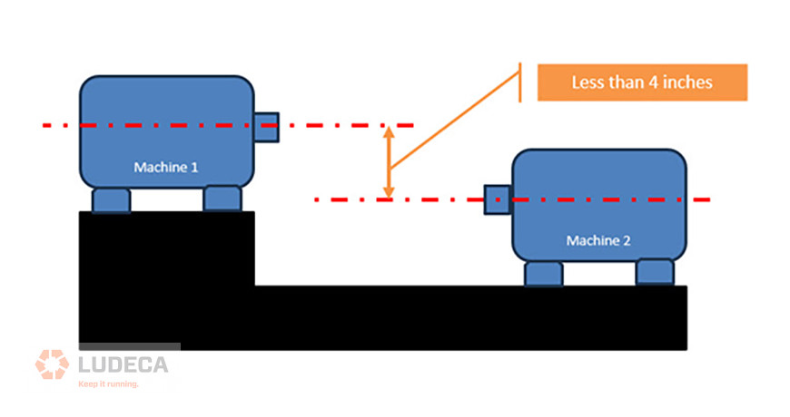
- The offset between machine shaft centerlines does not exceed 4 inches as shown in Figure 1 below.
Using either of the recommended laser alignment systems, select machine train alignment and configure the machine train so as to make the cardan shaft the middle machine. Now measure the misalignment across the left-hand U-joint (Coupling 1) and then the right-hand U-joint (Coupling 2). See Figure 2 below.
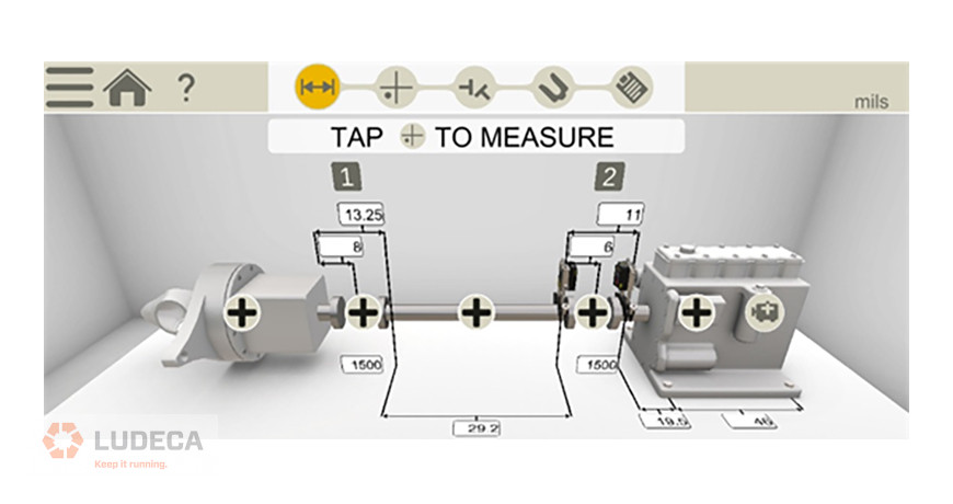
Machines with a cardan shaft have a predetermined offset between them. Therefore, we only need to make sure that the two machines are parallel to each other by eliminating any angularity between them.
Correcting the angle of the movable machine can be done by making the position value of the front foot and rear foot of the movable machine the same with respect to the stationary machine.
Click here for additional information or to download the step-by-step procedure!
A Successful Cardan Shaft Alignment on a Boat using Multipoint Measurement
by Diana Pereda
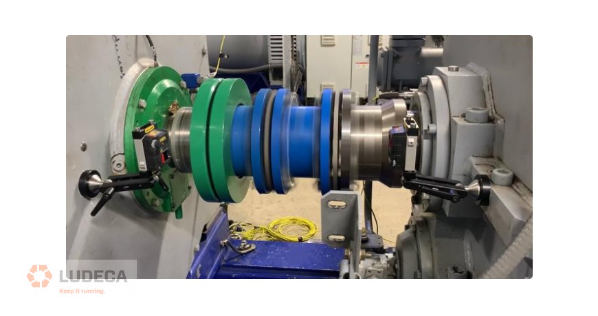
This is where it all gets interesting.
Thermal growth is mainly caused by the temperature difference in a machine when it is offline (cold) vs. online (hot). High temperature causes metals to expand, and different parts of the machine will expand differently depending on the material. This can cause a machine that is perfectly aligned while not in operation to be misaligned out of tolerance when it’s running.
How do we measure thermal growth?
Thermal growth can be measured by first taking an alignment reading when the machine is cold and again immediately after it stops, when it has reached full operating temperature. However, this method might not always be practical due to safety concerns.
Easy-Laser’s dynamic measurement brackets and the program EasyTrend are specially designed to deal with this. The brackets allow us to mount the laser measuring units on the driver and driven machines and measure alignment values in real-time, while the machine is operating. They are specially designed to prevent the transfer of machine heat to the measuring units, as you can clearly see in the infrared image below.

Gearbox – generator alignment on site
Our partner SCI was recently called to perform an alignment job in an energy plant outside of the city of Puebla in Mexico. The machine train consisted of a combustion engine, a gearbox, and an electric generator. The customer stated that they had aligned the train before, aiming for a tolerance within 0.06 mm in cold condition. The manufacturer had not provided any information about thermal growth.
Fransisco Sosa from SCI explains:
“We decided to perform some measurements using the EasyTrend program to achieve precision alignment of the gearbox–generator coupling during operating temperature (hot condition).
In this case, the dynamic measurement brackets were very helpful. Once they were mounted on the machine, we started measuring from the startup of the equipment and then for approximately 3 hours to see the thermal growth.
We were able to see in real-time that the gearbox moved 0.53 mm in the vertical direction due to its operating temperature, which was almost 80 °C. Movement in the horizontal direction was negligible. The operating temperature difference between the gearbox and generator was approximately 30 °C.
When the equipment was turned off, we kept measuring the dynamic movement without vibration during the cool-down period (8 hours), to corroborate the result.”
The measurement report
The black line in the graph shows the offset and angularity in the vertical direction, and the yellow line shows the horizontal direction. The expected thermal growth can clearly be seen.

When checking the alignment after some time of operation it showed the equipment was well within tolerance, as you can see in the report.

In conclusion, dynamic measurement is a great complement that offers valuable real-time insights into your machine’s performance. It will not only help to extend its service life but also minimize downtime and maintenance costs – and at the price of two additional brackets, that is cheap insurance!
Thank you Easy-Laser for sharing this informative article with us!
Watch our Shaft Alignment Know-How: Thermal Growth video to learn the importance of accounting for thermal growth on rotating equipment.
Thermal Growth in Alignment Components: Achieve Reliable Results With These 4 Tips
by Diana Pereda
When dealing with the alignment of a gearbox that has 3 pairs of feet, there are three possibilities when using the Easy-Laser Generation XT systems:
Option 1:
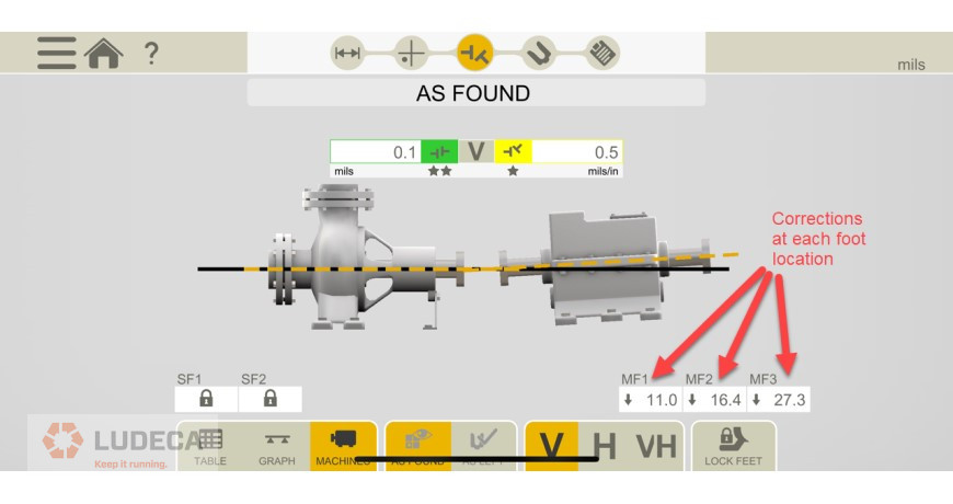
If the feet are located under the shaft and bearing housings, view the gearbox as a normal 4-footed machine. This will give you inboard and outboard corrections for the feet. The end that has the 2 feet should be corrected evenly, and the 3rd foot should be corrected as per the screen.
- Example foot configuration:
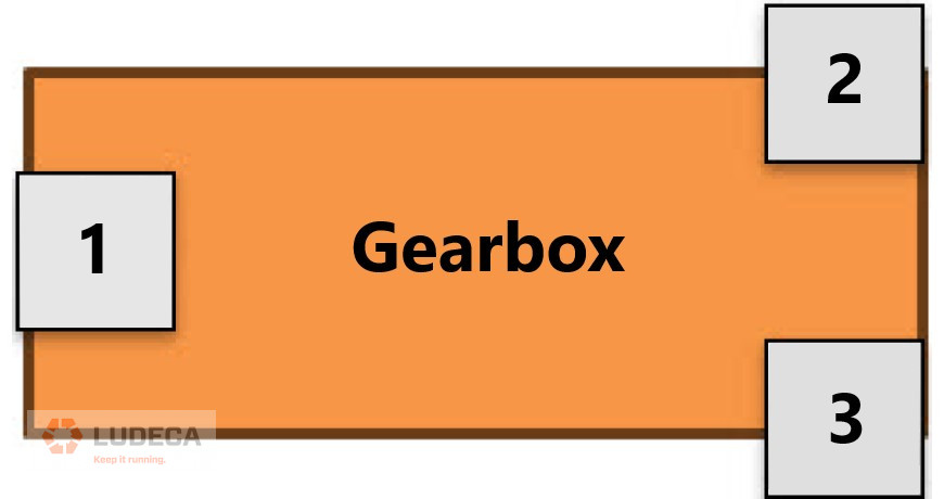

Dimensions set-up:
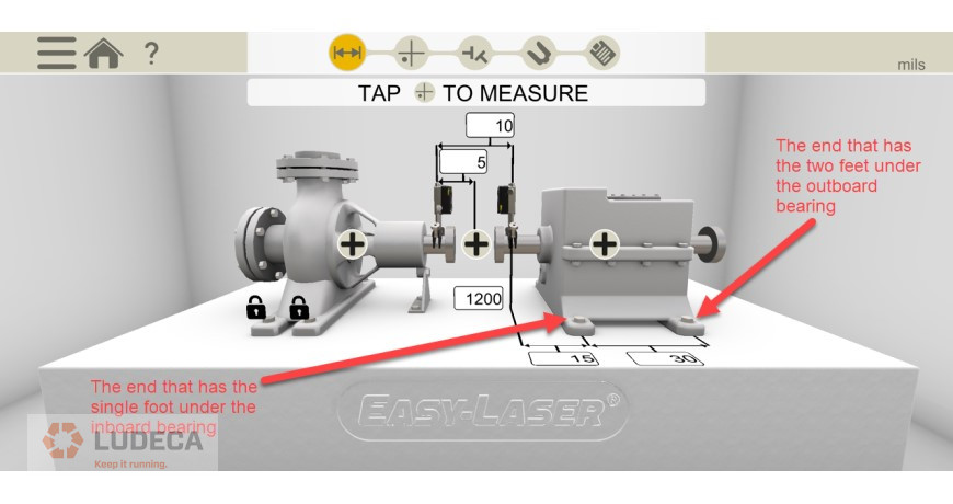
Results view:

Option 2:
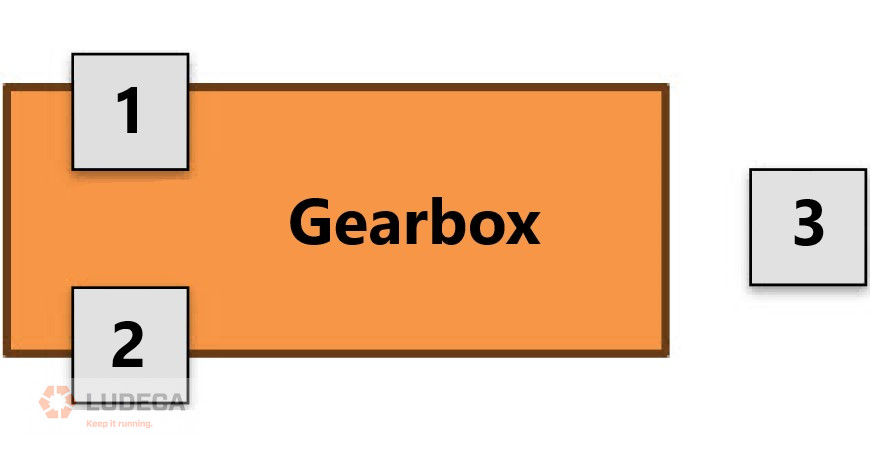
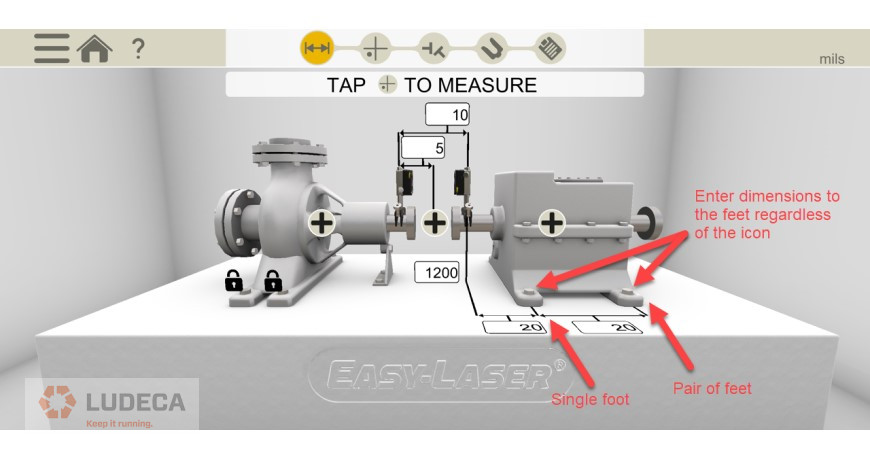
If the feet are not located under the bearing housings, you will still view the gearbox as a normal 4-footed machine. Enter dimensions to the feet and disregard the icon or image of the machine on the alignment tool. Just like in Option 1, the end that has the 2 feet should be corrected evenly, and the 3rd foot should be corrected as per the screen.
- Example feet configuration:

Dimension set-up:
Results view:
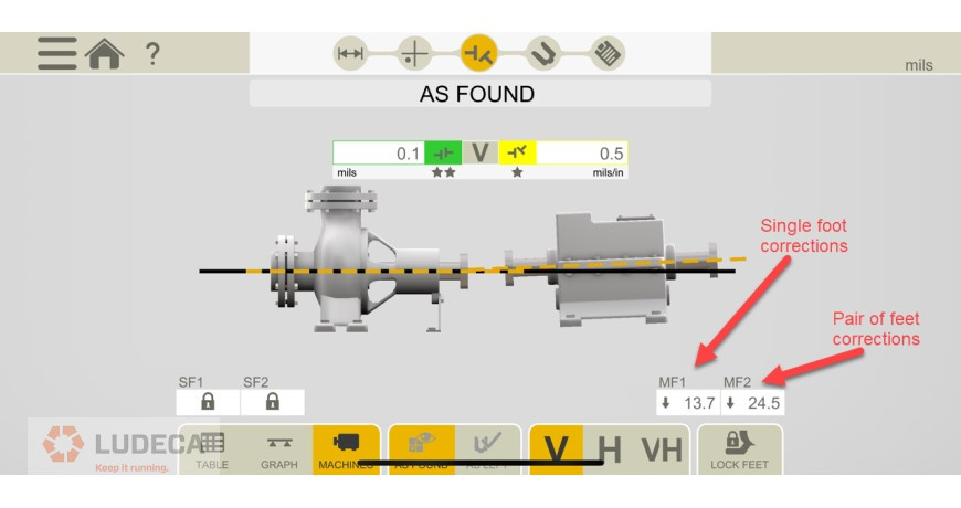
*Note for Option 2: The location of the single foot will not affect the set-up or results. If the single foot was on the outboard side the process would be the same.
Option 3:
If the feet are on the sides of the gearbox, or not under that shaft or bearing housings, then configure the gearbox as a 6-footed machine. This will give you corrections for the inboard, middle and outboard feet. Correct accordingly at each foot.
- Example foot configuration:
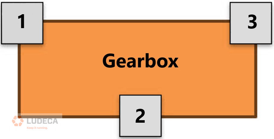

Dimension set-up:

Results view:
3 Signs your Gearbox, Pump and Motor Shafts are not in Alignment
by Diana Pereda
When we talk about industrial machinery, precision alignment plays a pivotal role in ensuring optimal performance and long life. Misalignment between rotating machines can lead to various symptoms that, if left unaddressed, can bring out significant operational issues. Whether we’re talking about pump and motor skids, turbines and compressors, or engines and generators, the impact of misalignment can be costly and interrupt your everyday operations. Below, we explore five common consequences and their symptoms of not performing precision alignment, and understanding the harmful effects they can have across different industrial facilities.
- Vibration: This is easily one of the most noticeable symptoms of misalignment in rotating machines. When shaft centerlines are not properly aligned, this creates uneven forces during operation, leading to vibration throughout the system. This vibration not only compromises the smooth operation of the machine but can also result in faster wear and tear on components. For example, in a centrifugal pump, misalignment between the motor and pump shafts can cause vibration, leading to premature failure of bearings and seals.
- Increased Noise Levels: Misalignment can also show up as increased noise levels in rotating machinery. When components rub against each other due to misalignment, it creates noise that is often louder and more pronounced than usual. This noise can range from a low hum to a loud clank, depending on the severity of the misalignment and the speed of the machine. For example, in a turbine-compressor system, misalignment between the turbine and compressor shafts can produce a distinct whining or grinding noise, indicating potential misalignment issues that need to be addressed quickly.
- Heat Generation: Another symptom is the generation of excess heat during operation. When components are not properly aligned, friction and heat are generated as they rub against each other. This heat buildup not only reduces the efficiency of the machines but can also lead to greater thermal expansion, exacerbating the misalignment issues. This excess heat can also have deleterious effects on the grease in the machine bearings, breaking down its properties. In an engine-generator set, misalignment between the engine and generator shafts can result in overheating, potentially causing damage to critical components such as bearings, flywheels and crankshafts.
- Premature Wear and Tear: Misalignment accelerates the wear and tear of rotating machine components, significantly reducing their operating life. When shafts are misaligned, it increases stress on couplings, bearings, and other components. Over time, this can lead to premature fatigue and failure, requiring costly repairs or replacements. For instance, in a gearbox-driven conveyor system, misalignment between the gearbox and conveyor shafts can cause accelerated wear on gears and bearings, leading to unexpected downtime and extra maintenance expenses, not to mention loss of production.
- Reduced Efficiency: Possibly the biggest symptom of misalignment is reduced efficiency. Misalignment hampers the smooth operation of machinery, resulting in increased energy consumption and decreased performance. Inefficient operation not only leads to higher operating costs but also impacts productivity and operating capacity. For example, in a centrifugal compressor system, misalignment between the compressor and driver shafts can reduce the efficiency of the compressor, resulting in lower output of compressed air, or other gases, impacting production efficiency down the line.
In conclusion, the alignment of rotating machines to precision tolerances is crucial for maintaining optimal performance and reliability across all industrial sectors. By being proactive and addressing misalignment, maintenance departments can reduce the negative effects of the symptoms discussed here. Laser alignment technology such as Easy-Laser’s XT770 offers a precise and user-friendly solution for achieving and maintaining alignment of rotating machinery. With laser alignment tools, industrial facilities can optimize asset performance, minimize downtime, and reduce maintenance costs in the long run. Investing in precision alignment is not only a best practice; it should be a priority for ensuring the continued success and effectiveness of industrial operations in today’s cost-conscious market.
Watch our Shaft Alignment Know-How: What’s Misalignment video and learn the causes and effects of having misalignment in your rotating equipment.
by Adam Stredel CRL
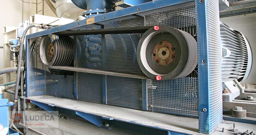
Proper location is very important when collecting vibration measurements on a belt system. If possible, one reading should be taken in line with the sheaves and one reading perpendicular to them on each bearing. Vibration data resolution should be taken into account so that proper separation between belt and driver frequencies can be obtained. Care should be taken to ensure proper belt alignment as well. A laser pulley alignment tool provides the most efficient means to properly align belts. Another issue is how the belts are installed. Was the equipment loosened and the belt put on properly? Were the belts instead rolled on by force, creating potential issues? Have you ever seen a Vee belt running upside down? This is usually caused by the cording in the back of the belt being broken often caused by rolling on the belts. Are sheave gauges being used to check the sheaves for wear? In some cases, the cost of a belt is more than the cost of a new sheave. These are just some of the things to consider for proper installation, maintenance, and identification of belt-related problems.
Don’t just assume that belts are simple and do not require best practice actions for proper operation.
Don’t Forget To Inspect Your Belts! 9 Preventive Maintenance Tips
by Gary James CRL
If non-repeatability is an issue and ambient vibration or mechanical looseness in the setup of the laser has been ruled out, then it may be of interest to check the bearing clearances. This can be accomplished very easily with a laser shaft alignment system. A little bit of information is necessary to accomplish this. We will need the following:
- Acceptable bearing clearance values and tolerances.
- The distance between bearings.
- The distance from the receiving laser (the “M” laser) to the first bearing.
- Easy Laser XT770 shaft alignment tool
For instance, suppose that the distance between bearings is 10 inches, the distance from the M-laser to the first bearing is 5 inches, and the acceptable clearance is 4 mils. This means that with the shaft bottomed out in the bearing, there is a total of 4 mils of clearance available, or lift.
Select the “Values” app and set the lasers at the 12:00 o’clock position; press the SET ZERO button and record the position. This will give you a zero reference for the values displayed on the sensors. See Figure 1:
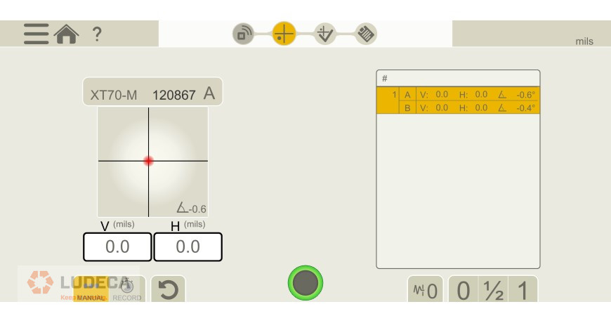
Using a carefully controllable lift mechanism (such as a hydraulic jack stand) carefully lift the shaft until it contacts the top of the bearing and record the position. See Figure 2:

With the above distances, we are allowed 4 mils/10 inches, (or 0.4 mils/1 inch), 10 inches being the distance between the bearings. From the receiver to the front bearing is 5 inches, so with a good bearing, we would expect to see another 2 mils/5 inches, (or 0.4 mils/ 1 inch). Add the two together and we get a total of 6 mils/15 inches. This means that if the lift of the shaft shows 6 mils of change at the M-Laser, the clearance is acceptable. If greater than 6 mils, clearances may be excessive.
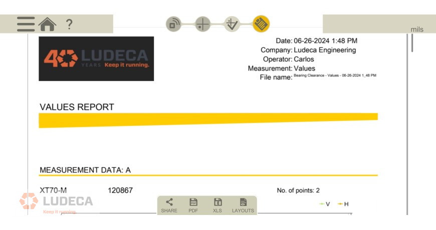
If documentation is needed, touch the clipboard icon to create a PDF report of the measurement. Shown below:
by Diana Pereda
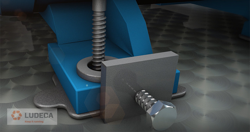
When moving machines for alignment, always use jackscrews. If you don’t have them, beating on the machine frame with a steel-face hammer is a lousy idea.
First, you run the risk of damaging the bearings, seals, and other delicate components in your machines. Secondly, you have little control over the magnitude of your moves. Thirdly, it’s unprofessional. If you don’t have time to weld or screw-on jackscrew assemblies, consider using a couple of carpenter’s pipe clamps, tensed against each other. This makes for a handy portable jackscrew arrangement that is safe, inexpensive, and offers you plenty of control. If this is not possible either, and you must hit the machine with a hammer, then at least do so with a plastic-face, shot-loaded dead-blow hammer.
How to Analyze Unexpected Results After Performing a Shaft Alignment Horizontal Live Move
by Ana Maria Delgado, CRL
With over 14 years of experience in the complex industrial world, it has become evident that certain individual parts within pumps and motors stand out in reaping the benefits of precision alignment. Let’s start with pumps, an indispensable machine in various industrial processes for moving fluid through the plant and maintaining system pressures. Achieving precision alignment is instrumental in increasing the life of certain components within pumps, such as impellers, seals, bearings and shafts. Performing precision alignment not only minimizes wear and tear but optimizes efficiency, ultimately extending the overall lifespan of the machine and contributing to the reliability of the entire system.
Shifting our attention to motors, the unsung heroes driving the majority of industrial operations, the importance of precision alignment is highlighted when looking at certain motor components. Misalignment between two machines can have a crucial effect on elements such as motor windings, bearings and shafts, resulting in an increase in energy consumption, unwanted vibration, and premature failure. Prioritizing precision alignment after installation, and after repair or overhauls will prove beneficial, helping maintenance departments enhance motor efficiency, reduce maintenance costs, and fortify the overall reliability of the machinery.
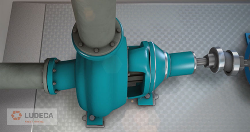
In the world of rotating machinery, laser alignment systems are a key tool in the arsenal of maintenance toolrooms. Laser alignment systems offer unparalleled accuracy for detecting soft foot and pipe stress, surpassing the limitations of traditional methods. Laser alignment eliminates guesswork, providing precise measurements and adjustments to save components such as couplings, shafts, and bearings within most rotating machines, as well as impellers and seals within pumps. Using laser alignment technology not only ensures optimal performance but also minimizes the risk of breakdowns. In essence, the pursuit of precision alignment is not just a best practice; it is a strategic activity for everyone aiming to maximize productivity in the ever-evolving landscape of industrial machinery.
Watch our Shaft Alignment Know-How: The Basics video to learn the fundamentals of precision machinery alignment.
I use a Laser Alignment System, so I am Performing Precision Alignment, Right?
by Adam Stredel CRL

Aligning belt drives and pulleys is crucial for several reasons:
- Efficiency: Precision belt pulley alignment ensures that power is transmitted smoothly from the belt to the pulley, maximizing the efficiency of the system. Misalignment can lead to energy losses and decreased overall performance. Such precision alignment is best achieved with tools such as the Easy-Laser XT190.
- Component Longevity: Correct alignment reduces bearing failures as well as wear and tear on belts, pulleys, and other related components. This extends their lifespan and minimizes the need for frequent replacements, reducing maintenance costs.
- Reduced Vibration and Noise: Misalignment can cause vibration and noise in the system, leading to reduced power transmission efficiency as well as potential damage to machinery.
- Energy Savings: A well-aligned system requires less energy to operate. Misaligned belts and pulleys can result in increased friction, leading to higher energy consumption. Proper alignment contributes to energy efficiency, reducing operational costs.
- Prevention of Overheating: Misalignment can generate excessive heat due to increased friction. This can lead to overheating of components, reducing their effectiveness and potentially causing damage. Proper alignment helps prevent these issues, ensuring optimal operating temperatures.
- Improved Performance: Properly aligned belts and pulleys contribute to overall system reliability and performance. It reduces the likelihood of unexpected breakdowns and ensures consistent operation over time.
- Enhanced Safety: Misaligned belts and pulleys may pose safety risks as they can lead to unexpected failures or accidents. Proper alignment reduces these risks, creating a safer working environment.
- Cost Savings: The combination of increased efficiency, reduced maintenance needs, and lower power consumption translates into cost savings over the long term.
SUMMARY:
Aligning belt drives and pulleys is essential for maximizing efficiency, extending component life, reducing vibration and noise, saving energy, preventing overheating, improving overall performance, enhancing safety, and realizing significant cost savings.
Using a laser alignment tool with visual targets such as the Easy-Laser D92 or the DotLine Laser can achieve greater accuracy than aligning by means of a straightedge or string. However, aligning with lasers that have a digital readout will achieve true precision, and in the case of the Easy-Laser XT190 generate documentation to prove that the work was achieved to specified tolerances.
Download our Pulley Alignment Guide plus 5-Step Procedure for information on the implementation of good pulley alignment of belt-driven equipment including terminology, alignment methods, belt maintenance, storage and tensioning as well as a 5-Step Sheave/Pulley Alignment Procedure.
Uncover Hidden Savings and Opportunities in your Belt-Driven Machines
by Ana Maria Delgado, CRL

What is torque?
By definition, torque is a twisting force, but as it pertains to fasteners, it is the amount of twist we put into that fastener to achieve clamping force with that fastener. Proper torque is the twisting force required to accurately apply the desired clamping force, working within the limitations of the fastener and the materials to be fastened.
What is the reason behind proper torque?
What are we trying to hold together? Different materials call for different torque. Higher loads require higher torque. There is a design parameter that calls for the correct amount of clamping force. The expected performance of equipment is best met when specifications are maintained. Under-torqued conditions normally lead to mechanical looseness. An over-torqued condition can lead to distortion, fastener fatigue, parts fatigue, and structural failure or broken components.
How to store torque devices
Most technicians have been told throughout their career to store a torque wrench at a “0” load. This, in most cases, is incorrect. If the torque wrench is the spring-loaded type, with a rotating handle to set the spring tension, the tool manufacturer normally indicates a specific setting to properly store the device. If left at “0”, the spring is allowed to expand and contract with temperature changes, changes in humidity, or vibration from transport. By having some tension on the spring, those changes are reduced to a minimum effect on the tool’s ability to achieve accurate torque. Newer torque wrenches, like a digital one or the Pall-Pull wrenches, do not have this issue and can be left at the set point for the last use.
How to prepare for proper torque
- What is the torque spec? Most equipment manufacturers will give specifications for fastener torque. If not, standard torque charts are available almost anywhere. Specifications are given for different thread diameter, thread pitch, and quality (or grade) of the fastener.
- To lubricate or not? Adding any sort of lubrication to the fastener drastically changes the coefficient of friction required to apply that twisting force, which in turn changes the clamping force of the fastener. Most manuals will include a note as to what kind of lubrication is to be used if any.
- Proper tooling: Having a tool capable of applying accurate torque is at the heart of the operation. Adding a longer handle to a smaller torque device is not a good way to maintain accuracy. Always work within the design limitations of the tools.
- Proper techniques: Torque should always be applied in a smooth, repeatable manner. Jerking motions on the end of the handle yield much higher loads. Applying the old “double click” trick vastly changes the torque on the second click and should not be done. If you want to verify that something is properly torqued, let everything relax, and apply force smoothly. If the fastener does not turn anymore when the device indicates the desired torque, then it was properly torqued
What to inspect for proper torque
Over time, things can affect how the clamping force changes in a fastener. Heat, vibration, load cycles—all of these can reduce the ability of a joint to maintain a working condition. In some instances, regular checks are required, with intervals that open as the joint is constantly found to be properly torqued. The first time a joint is found to be loose, the interval goes back to short-term checks to prevent failure. Sometimes, the simplest indicators work the best. Cracked paint marks, bolt tabs, or even safety wire can give quick inspection points, and ensure that everyone did their part to #Keepitrunning.
Visit our Knowledge Center for resources and tools to help you succeed when implementing and using our maintenance technologies.
Precision Maintenance: The Torque Wrench. Check Out These 15 Helpful Tips!
by Diana Pereda
Visiting more than 150 industrial sites has helped me realize that precision laser alignment tools have become a focal point in most companies’ maintenance strategies. One significant advantage of employing laser alignment tools is the unparalleled accuracy they offer in aligning rotating machinery. The precision achieved with these tools ensures that critical elements such as shafts and bearings are excellently aligned, reducing wear and tear. This, in turn, extends the lifespan of rotating assets, minimizing the frequency of breakdowns and subsequent downtime. The efficiency gained from precision laser alignment directly contributes to increased reliability and operational continuity, aligning seamlessly with our commitment to optimizing asset performance.

However, it’s crucial to acknowledge the investment and training required for implementing laser alignment tools. The initial cost of acquiring these advanced maintenance tools can be a deterrent for some industrial facilities. Moreover, ensuring that maintenance personnel are adequately trained to operate the laser alignment tool effectively is essential. This training incurs additional costs and may pose a challenge in terms of time and resources. Additionally, as with any technology, there is a learning curve associated with the adoption of laser alignment tools. It may take some time for the maintenance team to become fully proficient, potentially leading to a temporary decrease in efficiency during the initial stages of implementation. Choosing a company like LUDECA that provides resources such as the 5-Step Shaft Alignment Procedure below and providing short and long courses discussing alignment fundamentals, can help expedite that learning curve.
Despite the challenges, the long-term benefits of precision laser alignment tools outweigh the drawbacks. The increased accuracy and efficiency over older methods, reduced maintenance costs, and extended lifespan of rotating assets make the investment worthwhile. As we, in the industry, continue to prioritize the optimization of our processes, the adoption of laser alignment tools remains a strategic move towards achieving operational excellence and ensuring the sustained performance of our rotating machinery.
by Adam Stredel CRL

Casing distortion is not only one of the biggest problems for rotating machinery, it’s also a very common one. But what does it actually mean? To explain it, we can use the famous analogy of a rocking table in a restaurant. This is a situation everybody can relate to. Due to an uneven floor or bad construction of the table, there is space under one leg which makes the whole table rock from one side to another. It’s a problem that is easy to solve; just use a few napkins, and the table will stay still.
The same happens when placing rotating machinery on a foundation that is not flat. Most rotating equipment is designed to be installed on a flat surface. At the manufacturer site, all machine feet are milled to be in a perfectly flat plane. When placing the equipment on a non-flat foundation or uneven sole plates, it will reproduce that rocking situation we just mentioned. That is what we call “soft foot.”
Tiny clearances, big impact
Rotating equipment consists of many parts: rotors, shafts, bearings, mechanical seals, and impellers in compression chambers – just to mention a few. And these all have very small internal clearances. If a machine is bolted down on an uneven surface, the forces applied on the machine’s feet will change the casing geometry. As a result, these clearances will quickly change.
To fix a soft foot condition, it is necessary to compensate for everything above 0.05 mm. That is not much if you consider the fact that the thickness of a human hair is between 0.06 mm to 0.08 mm! This is how little it takes to convert our new or newly overhauled machine into a victim of casing distortion.
Pipe connection issues
Another possible cause for casing distortion is pipe strain. Pipe strain can occur when the pipes are wrongly fabricated and the connection flanges are not aligned. It can also be that the pipe supports are too high or too low, which creates large gaps between the connections. A common solution for this is to force them together, which will result in what we call nozzle load. This, too, will put a lot of stress on the machine casing. (The OEM will specify the allowed nozzle load on the equipment.)

The long-term consequences
So, what kinds of problems can you run into if casing distortion occurs? Previously, we mentioned the internal parts of rotating machinery, such as shafts. How do they get affected?
Well, shafts have mounted bearings to carry the rotating motion, and these bearings operate under designed loads. When casing distortion occurs, the shafts are put under strain and their positions change. That will affect the bearings by changing their designed load, and the rolling elements inside the bearing will move from the designated raceway. This is something that will seriously affect lubrication. The rolling elements of the bearing will push away the lubrication since there will be no space for it. Heat will build up and produce more thermal expansion of internal components, which will gradually reduce their gap until, inevitably, failure occurs (Changing the designed loads in the bearings will reduce bearing life by as much as 50%).
Ensuring proper installation can make the difference between smooth operation and unexpected failure. As we’ve seen, all it takes is a minor gap to throw your machinery off balance. When it comes to rotating equipment, precision is a necessity.
Thank you Roman Megela with Easy-Laser for sharing this informative blog with us!
Visit our Knowledge Center for resources and tools to help you succeed when implementing and using our maintenance technologies! Watch our video tutorials, download infographics, plus explore other helpful information to reduce equipment failures and downtime.
by Diana Pereda

Ensuring proper sheave alignment on multi-belt drives involves several good practices. When dealing with multiple belts and sheaves, a thorough inspection of each belt and its grooves for wear is crucial. In cases where any belts are slipping, it becomes imperative to replace all belts together.
Achieving precise alignment between pulleys can be accomplished through various methods. One approach involves using a machinist’s straightedge, while another entails placing a tightly drawn piece of string across the faces of the sheaves to verify if all four points of contact are made. Alternatively, employing a laser pulley alignment tool such as the Easy-Laser XT190 provides a more advanced and accurate alignment solution including the ability to generate an alignment report.
Regardless of the chosen alignment method, it is advisable to monitor changes in angularity and offset of the sheaves during the belt tensioning procedure. This monitoring should coincide with the tightening of hold-down bolts on the machine being adjusted, to ensure no unwanted or unexpected movement occurs during the tightening procedure. By doing so, the alignment can be maintained accurately, ensuring optimal performance and longevity of the multi-belt drive system.
Download our 5-Step Sheave Pulley Alignment Procedure for a simple and effective procedure for sheave pulley alignment of belt-driven equipment.
Now You Can Detect and Quantify Belt Driven Rotating Equipment Defects!
by Ana Maria Delgado, CRL