Q1. Why is it necessary to look at alignment condition results at the coupling? Why can’t I just get my feet to within 2 thousandths to finish the alignment?
Because the numbers at the feet are only a rough guide to the actual alignment condition. Large corrections at the machine feet don’t automatically point to a misaligned coupling, in which case you are spending more time than necessary on an alignment. The opposite can also be true. Small corrections at the feet don’t automatically mean your alignment at the coupling is good either, in which case you are bolting down a misaligned machine. The coupling is where we want to establish the true alignment condition. Not only is this the point of power transmission but it is also the point where the alignment condition is displayed and specified, and where it can be easily compared to tolerances. Of course, a very experienced aligner, with a good sense for the geometry of the machines, can glean an insight into the alignment condition from the correction values at the feet, but unless precise Rise/Run calculations are performed, the actual alignment conditions at the coupling will not be immediately apparent.
Q2. Why is the coupling our focus?
Two shafts with excessive offset between them at the coupling lead to premature wear and tear of bearings, seals, etc., along with a decrease in efficiency, increased power consumption, increased vibration, and other harmful consequences. The driving machine transfers power and torque to the driven machine via the coupling, not at the machine feet.
Q3. The numbers are so small! How can the machines be misaligned?
Let’s look at an example. In Figure 1, the front and rear feet correction values are both 2 mils but with opposite signs. The distance from the coupling center to the front feet is 10 inches and so is the distance from front to back feet. Keeping your feet values in mind, the alignment at the coupling would not look so good. See Figure 1:
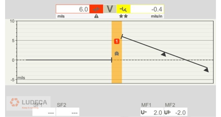
This demonstrates why solely using feet correction values to determine the state of an alignment can be so misleading. Our feet corrections are by no means large, yet the alignment is not within tolerance. Always look at the numbers at the coupling. One method of expressing misalignment is in terms of allowable offset at the coupling center, and angularity between the shafts. Neither alignment condition nor alignment tolerance should ever be notated only by using feet values.
Q4. Can you give me any guidelines or tips that I could use when looking at just the position values for the feet?
In the field you may get bolt-bound or base-bound or come across a machine that is difficult to align. Therefore, it is always advisable to seek out the smallest moves possible necessary to achieve an alignment within tolerances. To efficiently rough-align the machine as well as possible, get the front feet position as close to the offset tolerance as you can. Finish the alignment by correcting the rear feet, with the goal being to decrease the offset at the coupling center or center of power of transmission points. Make sure that the signs (+ or –) of the feet correction value match, and that the back feet correction value is greater than that of the front. Examples: Front foot positive? Then back feet more positive. Front feet negative? Then back feet more negative. See Figure 2:
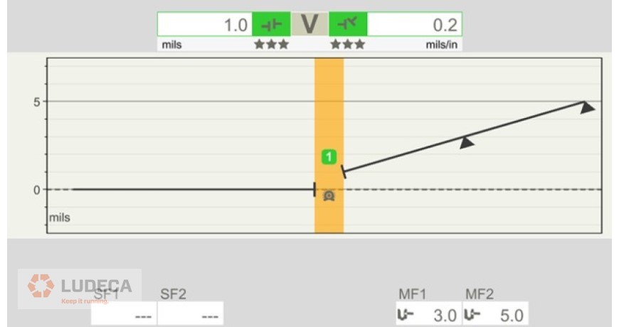
In Figure 2, the feet correction values are greater than those in Figure 1, yet the alignment is better, still within tolerance at the coupling. The offset between the shafts decreases as we approach the coupling, so that the offset falls within tolerance by the time the shafts meet at the coupling. The other parameter that must be controlled is Angularity.
Figure 1 is not within tolerance because leaving the front and rear feet with opposite signs makes it more likely to have a large offset at the coupling center. Having a greater correction value at the front feet also makes a large offset more likely even if both feet have the same sign. Both of these cases could be described as pointed away from the coupling, the opposite of what we want. This applies to both the vertical and horizontal corrections.
Q5. Any final thoughts on alignment tolerances?
We have tolerances because a perfect alignment is unattainable and unnecessary. It is only necessary to get the alignment “good enough”. Tolerances define what good enough means. One way to define that tolerance is by specifying the maximum allowable offset at the coupling center, as well as the maximum allowable angularity between the two shafts. This cannot be done with feet correction values without also specifying all the relevant distances like the distance between the front feet and the flex planes of the coupling. Doing this requires you to process more information and is not as simple as using the coupling values. The distances in question will vary from machine to machine. Focusing on the alignment condition at the coupling allows us to understand more with less information. The best laser alignment systems perform their tolerance evaluation based on the condition displayed at the coupling and compare it to the standards for the operational speed of that machine. The higher the RPM of the machines, the tighter the alignment should be at the coupling.
Check out our Easy-Laser XT Series, with built-in alignment tolerances giving the user the freedom to choose between traditional tolerances, the new ANSI standards, or custom tolerances of the user’s own choosing.
Filed under:
Alignment by Jim Larochelle