You have invested in a high-precision laser shaft alignment system or vibration data collector/analyzer. Why? Because you want more accurate alignments and vibration measurements, done in less time.
But, what if some incident rendered your tool less accurate, or even wrong altogether? If accurate measurement and tight tolerances are key to your vital processes, this would be a grave concern. Proper operation of your critical machinery or safety systems depends on excellent alignment with low vibration under running conditions.
Perhaps your tool was subjected to temperature extremes, or you dropped your laser or sensor, and even though they are shockproof to the IP-65 standard and didn’t break, they are now out of calibration? What if you are trending data for preventive or planned maintenance, and two different tools used for the same measurement significantly disagree? Only a NIST traceable and certified calibration verification can ensure that your systems are working as designed and within tolerances.
Our highly accurate NIST-certified calibration verifications are performed within a 48-hour turnaround time under tightly controlled conditions to NIST standards in a climate-controlled laboratory. For our laser alignment systems, a biennial check (every two years) is recommended. For vibration data collectors and analyzers, a biennial check is recommended also, or whenever the instrument informs you that one is due.
by Alan Luedeking CRL CMRP
PLANT SERVICES • JULY 2011
Misaligned pumps can affect energy efficiency
Align pumps with laser accuracy.
By Heinz P. Bloch, P.E., Process Machinery Consulting
In brief:
- Intern approaches pump laser alignment with laser accuracy.
- Tips to compare the energy wasted by a hot coupling to the energy loss.
- Misalignment affects bearing load and excessive bearing load causes exponential decreases in bearing life.
In the summer of 1994, Jack Lambley, an intern at Imperial Chemical Industries’ (ICI) Rocksavage site in the United Kingdom, was quantifying the effect of misaligned process pumps on power consumption. He arranged to have a surplus pump overhauled and fitted with new bearings. He then had the pump installed in a suitably instrumented closed-loop arrangement operating on the water. Prüftechnik loaned Lambley a laser-optic alignment instrument.
As an undergraduate student, Lambley had learned that misalignment affects bearing load and that excessive bearing load causes exponential decreases in bearing life. His supervisor, Steve Moore, had asked Lambley to read the engineering sections of SKF’s general catalog, which stated that a 25% increase in bearing load cut its rated life in half.
Continue reading “Misaligned pumps can affect energy efficiency”
by Ana Maria Delgado, CRL
One hour-long presentation by Alan Luedeking , training instructor and field service engineer for alignment of rotating machinery at LUDECA. Originally filmed at the CBM 2011 Condition Based Monitoring Conference at the Reliability Performance Institute in Fort Myers, Florida.
This presentation is an in-depth treatment of the subject of soft foot, or machine frame distortion, indirectly coupled rotating machines. The presenter will cover how to measure soft foot with different methods and discuss the pros and cons of each. He will also discuss how to diagnose and correct soft foot conditions, and will then take your questions concerning these topics.
Key Bullets:
- What is soft foot?
- What types of soft foot are there and why is this important?
- How do I measure soft foot correctly?
- How do I diagnose the soft foot condition I measured?
- How do I fix a soft foot?
Embed Code for flash video player – Flowplayer:
This video is courtesy of Reliabilityweb.com and was recorded at CBM-2011 live from the Reliability Performance Institute.
by Alan Luedeking CRL CMRP
Hot alignment checks are often unsuccessful because of delays in installing measuring devices on the equipment which has just been shut down.
Even when good planning and organization allowed you to take readings within minutes of the shutdown, these readings only address the so-called “Thermal Growth”. Often the effects of thermal growth on alignment had been calculated fairly accurately and the “hot alignment” check confirmed them, but still, excessive vibration persists and continues to be traceable to misalignment.
The problem is that machinery moves during operation for reasons unrelated to thermal effects.
Dynamic rather than thermally induced movements may cause machinery to operate misaligned. Since these dynamic effects disappear before the machinery stops rotating, hot alignment checks cannot measure them.
The non-thermal moves, both vertical and horizontal, are often as large or larger than the thermal moves but much more difficult to calculate. In our experience, dynamic moves are usually ignored.
These movements can be caused by foundation problems, pipe strains, and stresses, loose anchor bolts or changes in the load, etc. Whatever the cause or causes, almost the only way to determine the movements is through continuous computerized monitoring of the alignment.
When coordinated with records from the control room it often becomes clear why and how the machinery changed position. Proper “cold” alignment targeting thus becomes feasible and significant operational improvements are usually achieved.
Aside from the well-known consequences of less wear on bearings, seals, couplings, etc., it is sometimes possible to increase the load for the equipment, and last but not least, power consumption will reduce and result in savings which are a multiple of the cost of the monitoring equipment.
Several monitoring systems have been on the market for many years using dial indicators or proximity probes, etc. and now, fully automatic laser systems like the PERMALIGN® and the new Rotalign® Ultra LIVE TREND are available with suitably large measuring range.
by Ana Maria Delgado, CRL
Every asset-intensive organization understands that the greater the uptime of machines, the more efficient and cost-effective operations will be. Keeping your assets in optimal working order is easier and more cost-efficient when advanced technology such as laser shaft alignment is used to increase machine reliability.
The Machine Maintenance Goal
One of the goals of every production-oriented operation is to keep its machines operating at the lowest cost yet highest productivity levels. In order to do so, proper maintenance must be performed on machines. The level of maintenance care of machines can be broken down into four major categories:
- Purely reactive or run to failure
- Basic preventive maintenance and inspections
- Combination of predictive maintenance methodologies and preventive maintenance
- Organizations making use of preventive and predictive maintenance as well as advanced technologies such as laser shaft alignment, vibration analysis, infrared thermography, etc.
At the heart of most good maintenance operations is a CMMS system that records and tracks all asset detail and maintenance work information. The premise of a CMMS is that the more asset and historical work information you have, the more efficient and effective your maintenance planning will be.
Why Shaft Alignment Technology is Necessary?
A natural extension to using a CMMS is the use of advanced shaft alignment technology because it adds valuable information regarding the condition of the machines that might otherwise go undetected until machine failure occurs.
Typical signs of misalignment include:
- Abnormally hot components, the smell of burning insulation
- Bearing issues or grinding noises
- Higher energy usage
- Load imbalances
- Rotor bar problems
- Excessive vibration
One proven method for machinery alignment is laser shaft alignment. With up to 50% of damage to rotating machinery directly related to misalignment, correcting this problem in machines is critical to production as well as operating budgets. But these are not the only reasons:
Top 7 Reasons to use Laser Shaft Alignment
Laser shaft alignment can lower your operating costs through:
- Early identification of problems enables machine maintenance to be proactive.
- Reduced maintenance cost as a result of sharp reductions in bearing, seal, shaft, and coupling failures.
- Reduced vibration lengthens the useful lifecycle of the machine as well as increases the quality of output.
- Less unplanned downtime so production can be optimized.
- Fewer emergency repairs lowering labor costs.
- Error-free and accurate measurements to 0.0001″.
- Reduced energy consumption. Poorly aligned machines require more energy to achieve the same results as a well-aligned asset.
Who Can Benefit from Laser Shaft Alignment
Laser shaft alignment can be used in any industry ranging from manufacturing to the wind power industry that depends on machinery to function. Machinery alignment is a cost-effective solution whenever critical functions are at risk. Some examples include, but are not limited to:
- Processing and centrifugal pumps used by the petrochemical industry
- Boiler feed pumps are found in every power plant and also in general industry
- Vertical turbine pumps found at water treatment plants
- Refrigeration compressors used for food processing and cold storage
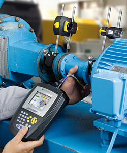 Protecting your machines through precision shaft alignment is not an option, it is a must in today’s competitive environment. Old dial indicator technology may have too low a resolution to measure accurately enough and are subject to reading errors and hysteresis or sticking dial hands. On the other hand, laser shaft alignment is error-free with reports generated directly from the instrument in conformity with ISO 9001 requirements.
“7 Reasons Why Machines Need Laser Shaft Alignment” was written for us by Stuart Smith, MBA, MS. He is an avid writer about CMMS and EAM software solutions for Mintek Mobile Data Solutions. Stuart has over 25 years of experience running operations in multiple industries.
by Ana Maria Delgado, CRL
Have you ever been forced to check for soft foot when your brackets were less than 10 inches apart and the MTBM’s supports were several feet distant? If you answer yes to that question or if you have ever made foot corrections under similar circumstances, then resolution matters to you.
Resolution: The smallest detectable increment of measurement.
Synonyms: sensitivity, fineness

For laser shaft alignment systems mounted on a pair of shafts, the resolution is the smallest movement between the two shafts that the electronics can detect. On all systems LUDECA sells, this value is 1 micron (.00004″) or better. Typically, for any measurement system to be accurate, it must have a resolution at least four times better than the minimum increment of value it is designed to display, and for a “precision” measurement instrument, this ratio should be ten times or better.
Linearity: The closeness of a calibration curve to a straight line. Having output directly proportional to the input.
Synonyms: Straightness, direct proportion.
For a laser shaft alignment system, linearity is easy to evaluate. A graph of the known position versus the displayed value should be a straight line. If it is, we say the system is linear. Our products are linear to one percent.
Repeatability: The ability of an instrument to reproduce displayed values when the same input is applied to it consecutively under the same conditions. Repeatability is expressed as the difference between two or more sets of measured values when given identical input positions of the sensor(s).
Reproducibility: The ability of the experimenter (user) to reproduce or duplicate the conditions of an experiment or measurement. Reproducibility and Repeatability are not the same, but Repeatability (of measurement results) depends on Reproducibility. For instance, if the anchor bolts are loose and the machine moves on you as you are turning the shafts to take alignment readings, your readings will not be repeatable, although they may be accurate for the conditions extant at each reading.
Accuracy: The ratio of the error in measurement to the ideal, or expected, value. How close a result is to the true value of the parameter being measured.
Synonyms: deviation, error, how close a value is to be correct or true.
Accuracy is how close a measuring system comes to measuring the truth. For specific measurements or specifications, the term error is used and is expressed either as a percent of full scale or as an absolute value. Accuracy is adversely affected by non-linearity, non-repeatability, poor reproducibility, and poor resolution.
by Ana Maria Delgado, CRL
This question is of importance because there are now a number of alignment systems on the market, using different methods. To answer, ask yourself the question: What do I want to accomplish? You want to bring offset and angularity within tolerance.
Rim & Face measures the offset through the RIM reading and measures the angularity through a face reading which can easily be inaccurate if the diameter at which it is measured is small such as 8″ or less, or even wrong if the shaft floats in or out during the measurement.
The reverse Indicator takes two rim readings which establish the offset and compute angularity from the difference in these offsets. It is not affected by moderate shaft float but is only accurate if the distance between the measuring devices exceeds 8″. Also, accuracy is dependent on measuring resolution which in the case of laser systems should be at least 5 microns if you expect to see improvements over normal dial indicator readings.
Offset & Direct Angle: Since offset and angularity are what you were out to measure, obviously a system measuring the RIM and DIRECT ANGLE is best, particularly if it also has a measuring resolution of 1 micron (.00004″) like our SHAFTALIGN®, OPTALIGN® SMART, ROTALIGN® ULTRA laser alignment tools.
by Ana Maria Delgado, CRL
June 2011 • TPO Magazine
ACING IT IN OKLAHOMA
Strong skills, preventive maintenance and good planning lead to success at the Coffee Creek Treatment Plant in Edmond.
The Coffee Creek Wastewater Treatment plant in Edmond, Okla., has had near-perfect compliance for 38 years and has won several awards, most recently 2010 Large Wastewater Plant of the Year from the Oklahoma Water and Pollution Control Association (OWPCA).
It all has happened with a staff of five, despite rapid population growth, several upgrades, and various episodes with collection system inflow and infiltration. “When you have only five staff, you have to focus on working smarter, not harder,” says Fred Rice, water resources superintendent for the city. This means preventive maintenance, SCADA monitoring of critical alarms, and ongoing equipment and safety training.
It’s also a matter of teamwork. Kris Neifing, chief plant operator, hired in 2004, supervises two operators, a maintenance specialist, and a lab technician, and is also responsible for one lift station at the plant and nine lift stations located throughout the collection system.
Rice credits Neifing and his staff for the plant’s track record. “Kris has really pulled everyone together as a team,” he says. “All the credit for what we’ve achieved in the last six years is due to Kris and his staff. My role is like coaching a sports team. You can coach them, but the team executes the plays.”
Says Neifing, “What makes us successful is that everybody has different skills that collectively make us the best we can be. Some are better at maintenance while others prefer operations. We believe that no one knows how to do their jobs better than the ones who do it every day.”
Continuous improvement
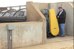
The plant’s compliance and safety record do not mean the staff is complacent. “We strive to continuously improve,” says Rice. “There is no process out there that can’t be improved, especially on the maintenance side.”
Rice and Neifing frequently attend the WEFTEC conference and other trade shows to check out the latest equipment. This has led to several innovations, such as vibration analysis and laser alignment equipment to help ensure that pumps and motors operate normally with the lowest possible maintenance. Rice and Neifing also read trade journals and network with others in the wastewater treatment business to glean ideas.
“The staff comes to us with ideas, like getting air compressors for maintenance, and suggesting better equipment or ways of doing things,” Neifing says. “We empower them to make suggestions, and we listen.” Adds Rice, “The city started a program based on the general concepts in the Good to Great book because we believe that organizations that excel are successful from the ground up. We give our employees responsibility and then hold them accountable.”
Read the entire article Acing it in Oklahoma
by Ana Maria Delgado, CRL
When craftsmen are given the task of laser alignment, quite a few assumptions are made. One very common assumption is that now that a laser system is being used, anyone can do an alignment. Another is that since a laser is being used, everything is alignable. Put a laser system on an unalignable machine and you will still have an unalignable machine, only with an expensive laser alignment system attached to it. A laser alignment system does NOT guarantee that a machine is alignable!!! (Actually, all machines are ultimately alignable, if only you throw enough time and resources at them- perhaps an entirely new base or foundation is needed, and/or redoing the entire piping. The question is, is it worth it in some cases? The point is, that just because you put a laser on a machine, that does not make it instantly alignable, vanishing all other problems.)
However, a laser alignment system, combined with a skilled and trained craftsman and a good alignment procedure, will greatly expedite alignments and help determine if a piece of equipment is alignable at all. The following is a tried and true procedure that will greatly expedite alignments.
Pre-alignment checks are critical in ensuring successful alignment. All surfaces should be clean and burr-free with metal-to-metal contact between the feet and shims, and the shims and base. Shim packs should be consolidated to three or four shims per foot. Jackscrews should be installed. A concentricity and runout check should also be done on the coupling and shaft. It is also a good practice to check the base for flatness.
The next step is to accomplish a rough alignment. Use whatever method that you prefer to get the machines reasonably close, or “eyeball” clean. A straightedge will work on some couplings in short-coupled machines. On machines with spacer couplings, the laser and a tape measure can be used very effectively. The purpose of this step is to remove gross misalignment and ensure that the laser and detector are in line enough to take readings. (Note that the best laser systems offer range extension so even rough alignment can easily be done with the laser.)
After your rough alignment has been accomplished, a rough soft foot check is in order. Eliminate any obvious rocking and fill any obvious gaps. This should be done with all hold-down bolts loose. Now it is time to use your laser alignment system. Make sure that all required dimensions are entered accurately and that initial alignment measurements are repeatable. Assuming you still have a rough alignment, a final soft foot check is in order.
Follow your laser system’s recommendations for this. The ROTALIGN® ULTRA even features a comprehensive soft foot wizard that guides you through the entire process, diagnoses the condition, and suggests a solution. After any corrections are made, retighten all hold-down bolts, then recheck each foot individually with all the others tight.
We recommend a tolerance of 2.0 mils or less. Now for the final alignment: The first correction that should be made is getting the vertical plane in tolerance. When making shim corrections, monitor the horizontal plane to make sure your machine does not move laterally too much. Once you are satisfied the vertical alignment is in tolerance, proceed to final horizontal corrections. Leave the hold-down bolts snug (not tight). They do not need to be all the way loose to make effective horizontal moves. This is where good jackscrews become invaluable, Try to avoid hitting machines with hammers. When the machine is within tolerance alignment is complete. Save the alignment file for documentation and future reference.
Many years of involvement with machinery alignment reveal that this is the best and fastest procedure for precision alignment. Each step is necessary and important in accomplishing the next step. Take your time and be diligent and you will succeed in your alignment.
by Ana Maria Delgado, CRL
May 2011 • MAINTENANCE TECHNOLOGY
Cardan Shaft Alignment: These applications aren’t as straightforward as others. Their special considerations call for special tools and approaches.
A Cardan shaft is, in the simplest terms, a spacer shaft with a universal joint coupling on each end. (Its name comes from a 16th-century Italian mathematician, Girolamo Cardano.) This type of arrangement allows power to be transferred between two machines that are offset from each other.
Widely used in industry, Cardan shafts have proven practical in applications where space is limited—as well as in situations where an element in the machine train (e.g. paper roll) may need to be actuated (dynamically positioned) to an alternate position when the machines are not running. The universal joint allows for limited movement without uncoupling. To ensure sufficient lubrication circulation, which in turn prevents the universal joints from seizing, Cardan shafts are normally installed with an angle from 4 to 6 degrees at the universal joints. Experience, though, has shown that the angle between the shafts of the driver and driven unit should be kept to a minimum, preferably less than 4.36 mrads (0.25 degrees). Ideally, the angles between the driver and driven shafts and the Cardan shaft, shown as ?1 and ?2 in Fig. 1, would be equal. Geometrically, this would equate to zero angularity existing between the driver and driven unit: In other words, the shafts of the driver and the driven machine would be parallel to each other.
Read the entire article Cardan Shaft Alignment featuring the ROTALIGN ULTRA laser alignment tool suited for cardan-shaft applications.
by Ana Maria Delgado, CRL
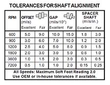 Some coupling manufacturers will sell couplings claiming that the coupling can take shaft misalignment. While this is true for most flexible couplings, it can be easily misinterpreted. Flexible couplings are designed to withstand, without damage, some shaft misalignment. Sometimes it is perceived that, since the coupling can take the misalignment, the machines can run under this condition without any consequences. When running machinery with significant shaft misalignment, bearing and seal life may decrease immensely, and other damage results. Therefore, for longer machinery life, it is always recommended to have equipment laser aligned to standard industry tolerances for shaft alignment, and not to the looser alignment tolerances allowed by the coupling itself.
Learn about Shaft Alignment Tools with Built-in Tolerances.
by Adam Stredel CRL

As the Project Manager for the Millwright Competition and a member of the 2011 ABC Craft Championship Committee, I want to thank you and your company for your support for the Millwright competition.
Even though I have never used that particular laser, it was very easy to use and only took about five minutes to become very comfortable with it. None of the competitors had used the SHAFTALIGN® prior to the competition, which was great. It only took about twenty minutes to show them how it operated, including thermal growth, soft foot, and static feet selection. Even though the competition required an 1800 rpm alignment with thermal growth, one of the competitors did a 7200 rpm alignment within the time limitation, which would never have been achievable with dial indicators.
I am proud to say that with your help and equipment this competition has finally evolved into a modern competition. Your alignment equipment is easy to install, easy to use, and accurate. It is the best alignment equipment that I have ever seen.
Again thank you for your support.
Ed LePage
Mechanical Craft Training Coordinator
CIANBRO Institute
Congratulations to Joseph Ducharme, the first-place winner.
by Ana Maria Delgado, CRL
March 2011 • IMPO MAGAZINE, iPurchase Supplement
As the American economy recovers, how aware, or active, are manufacturers concerning predictive maintenance?
Most manufacturers never lost the desire to increase their overall reliability and predictive maintenance efforts during the recent economic slowdown. Some companies did postpone purchases of predictive maintenance-related products. However, a lot of companies realize that an investment in predictive maintenance technologies is a viable means to decrease overall maintenance expenses, so they do it the right way. A lot of manufacturers, as a result of this understanding, continued to invest in predictive maintenance-related technologies during the recent economic slowdown. This allowed them to reduce overall maintenance costs and place their company in a more competitive position once the economy recovers. Interest in these products is higher this year as companies continue to invest in vibration- and alignment-related products to reduce their costs. increase competitive advantages, and manufacture equipment reliability.
Read the entire interview Q&A Roundtable from iPurchase, a supplement from IMPO Magazine including:
Are there any interesting trends occurring in the maintenance market?
Why do you think laser alignment is important to a manufacturer’s maintenance strategy?
How would you recommend a manufacturer approach the creation of a more robust maintenance plan?
by Trent Phillips
WaterWorld Magazine • February 2011
A Florida water treatment plant recently discovered that having full-flex (double engagement) gear couplings at either end of a spacer shaft connecting a Lufkin gearbox to a 13, 000 GPM Worthington water pump caused self-exacerbating vibration that eventually destroyed the gearbox twice within 3 months, requiring a full rebuild each time. After the second rebuild and re-installation, LUDECA was called in to monitor positional changes between the stopped and running conditions of the entire diesel engine-driven machine train with its PERMALIGN® system to derive true target specifications for the “cold” condition. Thereafter, a laser re-alignment to exact tolerances would be performed to the new targets…
Read the entire case study and view photos
by Alan Luedeking CRL CMRP
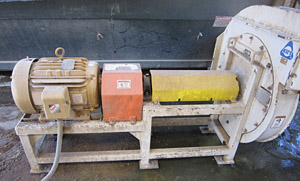
Problem: Exhaust fans
The exhaust fans at two of our process buildings kept having the same common faults (failed bearings, failed motors, and running hot.). We spent over $4, 400.00 on one fan from 2008 to 2010 and over $5, 600.00 on the other fan on parts alone.
Solution: Purchased an OPTALIGN® SMART EX laser alignment system
In July 2010, we received our new OPTALIGN SMART EX and had LUDECA come in and give us an introduction introductory training course. After a few trials on using the laser alignment tool on a motor and pump that we set up in the shop, we were ready to take it out in the field. We went and set the tool up on our two exhaust fans and found out there were way out of alignment. After a few tries, we had smiley faces on both machines in the horizontal and vertical directions. Since the alignment, we haven’t had any more problems with either fan. The OPTALIGN SMART EX is very user-friendly and well worth the money.
Now we have incorporated the OPTALIGN SMART into to our PM program to check the alignment on all rotating equipment as they come up for a PM. In the last few months we have been using it, we are getting good feedback from the maintenance department on how easy it is to use and how much time is saved, instead of doing it the old way (dial indicators). —Bryan Brown, PM Technician with MARTEK Biosciences in Kingstree, SC.
by Ana Maria Delgado, CRL
- Functionality: Do the Predictive Maintenance (PdM) tools you are considering have the ability to make all the measurements required by your physical asset management strategy? Are displays easy to see and interpret? Are the tools easy to learn and easy to use? Learn about our PdM tools. For Software, can it interface with your CMMS system? Can you import data from other systems such as oil data? Learn about our OMNITREND software.
- Durability: Will the tools hold up to your plant’s environment? Are they rugged enough for multiple users? IP ratings such as water–, dust– and shockproof are very important when dealing with industrial tools.
- Service: Will your vendor be available to answer questions or address problems should they arise? What is the vendor’s reputation for customer service? If you have a problem with a tool how soon can you expect a “loaner” until yours is repaired? Are the tools repaired and/or calibrated locally? Learn about LUDECA Repair and Calibration.
- Training: What are the training costs associated with learning how to use the tools? Is training included with the purchase? What training resources are available? Learn about LUDECA Training.
- Support: What level of support do you need? Does the vendor have a call-in tech support center, is it free or paid? Will the yearly costs of maintenance agreements make the tools considerably more expensive than competitors’ tools having similar capabilities? Do they offer free updates? Learn about LUDECA Technical Support.
by Bill Hillman CMRP
Pumps & Systems • January 2011
Aligning an electric motor coupled to a large air blower required multiple measurements.
Around 18 years ago, a client needed assistance aligning an electric motor (more than 1, 000 horsepower) coupled to a large air blower. This was a critical piece of equipment that was routinely shut down for preventive maintenance at regular intervals to ensure trouble-free operation. The mechanical contractor used for this alignment was reputable, and the customer had used him several times in the past for this task with satisfactory results.
Vibration Problems
Upon startup, vibration levels were so high that the package tripped and shut down before reaching full rpm, preventing any meaningful collection of vibration data to help identify the problem. This continued for two days. Convinced that the problem was alignment-related, the contractor made multiple corrections with the same results. Every time the package was started, vibration levels were high, and the package shut down before reaching full rpm.
Laser Shaft Alignment Assessment
The client requested that a shaft laser alignment system be used to ensure correct alignment. The motor and the blower were uncoupled, and all the hold-down bolts were at spec. Initial readings were taken. Remember, this was more than 18 years ago, so the alignment system was a much less sophisticated system than those available today.
Read the entire article Measure Twice, Cut Once!
by Dennis Onken
Machinery Lubrication, September • October 2010
In his book “Machinery Vibration: Alignment”, noted author and expert on precision alignment Victor Wowk illustrates the relationship between misalignment and loss of machine life. Of course, some equipment is more or less tolerant to misalignment depending on bearing type and coupling type. Likewise, the effects of misalignment are magnified as a function of speed.
Read the entire article Shaft Alignment has a Bearing on Lubrication Excellence
by Ana Maria Delgado, CRL
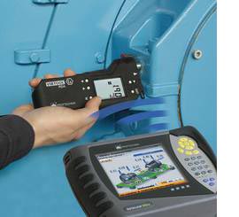 The ROTALIGN® ULTRA VIBRATION ACCEPTANCE CHECK works in combination with the VIBTOOL® vibration meter to measure vibration levels according to ISO 10816-3 international standards. The RMS velocity value is wirelessly transferred and stored back onto the ROTALIGN ULTRA computer where the result is instantly evaluated against the machine classification threshold. This fulfills the recommendation of the acceptance check after installation of rotating machinery or any alignment job, ensuring that machines run without restrictions. The VIBTOOL vibration meter can measure the following parameters: Vibration Severity, Bearing Condition, Temperature, RPM, and Pump Cavitation. More information about the new ROTALIGN ULTRA VIBRATION ACCEPTANCE CHECK
by Ana Maria Delgado, CRL
POWER-GEN Worldwide, September 2010
The alignment of turbine-generator sets poses unique challenges that only the best laser shaft alignment systems can overcome. Not the least of these is the difficulty of turning the shafts (either coupled or uncoupled) and the methods employed in turning them. The intent of this article is to present a few of these challenges and the solutions to them.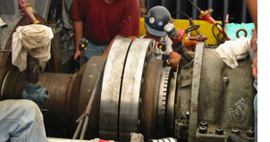
Shaft Rotation
Since a turbine-generator train cannot be readily rotated by hand (unlike most other smaller machine sets), external “helper” forces must be enlisted, such as an overhead crane with a sling around the shaft or coupling. As the crane applies rotational force it also lifts the shafts in the bearings a little, changing their relative alignment and true position in the bearings. This makes using the Continuous Sweep measure mode impractical since you do not want to corrupt the validity of the alignment data you are collecting as you rotate the shafts. The same concerns also apply to other methods, such as the chain fall and pin method…
Read the entire article Turbine-Generator Alignment featuring the ROTALIGN ULTRA alignment system.
by Ana Maria Delgado, CRL
