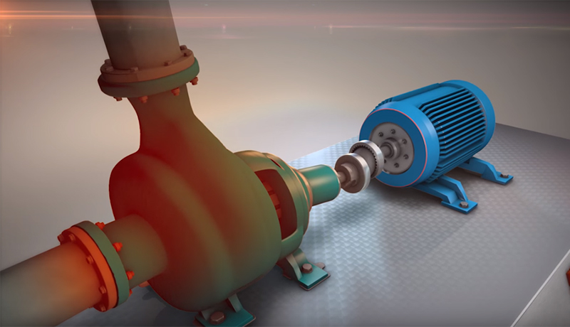
You’ve always heard the adage, “S” Laser on the Stationary and “M” Laser on the Movable.” In this day and age, however, this “truism” has almost become obsolete. You see, the concept of the “stationary” machine, per se, is obsolete. ALL machines CAN be moved if they really need to be (no machine grew out of the ground, like a tree!), so instead we emphasize that the “S” laser should be mounted on the machine that is “more difficult” to move (usually the pump because of the connected piping.)
The flexibility that all Easy-Laser XT-Series systems offer through their lock feet function, as well as the ability to freely flip or rotate the view of the machines to suit your needs, means that you no longer need to concern yourself with “stationary” machines. Your real goal is to find the easiest and most expedient way of aligning your machines. In some cases this may mean moving one pair of feet on the pump just a tiny bit to keep from having to move the motor feet a lot. This means you can save yourself from becoming bolt-bound, or base-bound (not enough shims left under the feet to be able to come down.)
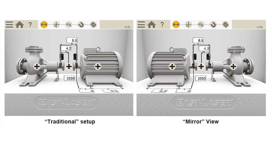
Traditionally, you always try to set up so that your Stationary (or Hard-to Move) machine is on your left, and your Movable machine is to your right. But what if your pump and motor are mounted close beside a wall, and you can only access the machines from one side? As luck and Murphy’s law would have it, that side is always “the wrong side”, with your pump on the right and the motor on the left, instead of the way you are used to seeing them. No matter! Still mount your “S” laser on the pump. Now, since the Easy-Laser XT system wants to move the right machine by default, you can now employ the “Mirror” feature, which will automatically swap the view of your machines left and right, so you can see them the way they really are in the field, and easily move the left machine instead.
If you have two equally hard-to-move machines, each of which you would ordinarily like to consider stationary (such as a heavily piped little steam turbine driving a heavily piped compressor), then it really just boils down to which machine (or combination of feet on both machines) is the most expedient to move. Just mount the “S” laser on the on the left as usual. You can always use the lock feet function to declare the machine on the right stationary and make the machine on the left movable, or ask the tool to make any combination of feet movable so as to find your smallest possible moves or optimal combination of moves to solve bolt-bound or base-bound situations in the field. The Easy-Laser XT products are especially versatile for this, since they let you explore fully optimized centerlines (move ALL the feet in the train), as well as under-constrained and over-constrained centerlines, to cope with the exigencies of the situations you encounter in the field.
Lastly, if you ever need to compare your alignment or your target specs to a drawing or to someone else’s report that shows the machines the other way around from the way you set up, you can always use the Mirror functionality to look at your results from the other side. You use this feature “after the fact”—in other words, after your setup is already complete, with readings taken and results obtained, you can still always rotate the view and see your results as if you had walked around to the other side of the machines.
To summarize, the concept of “Stationary” and “Movable” is history. Use the Mirror feature right at the beginning, when you set up, to make your setup conform to your actual situation in the field. Use the Lock Feet Function to make any machine movable or stationary, and to explore “best possible” correction alternatives. Lastly, you can also use the Mirror feature to look at your alignment differently, after it’s already done.
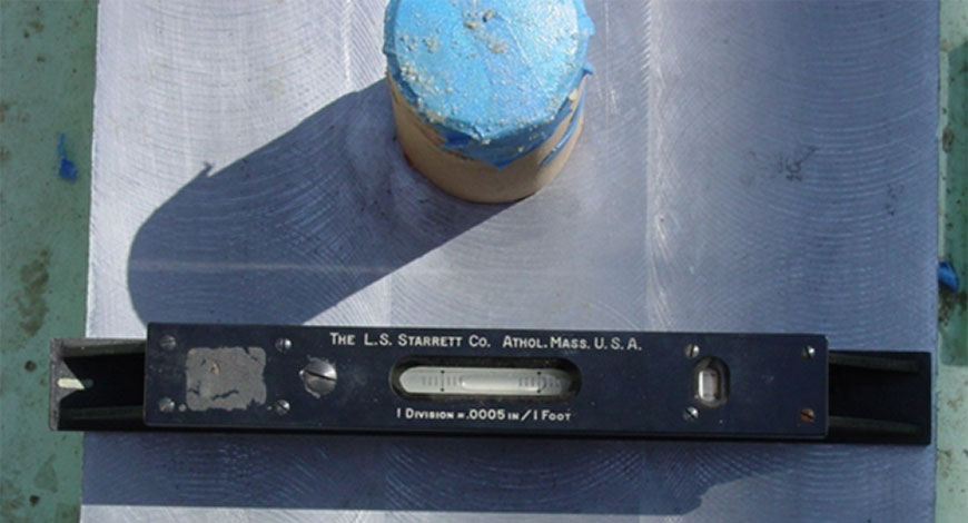
Baseplate tolerances, such as cited in ANSI/ASA Alignment S2.75-2017, specify that a baseplate must be level to <10 mils/ft, coplanar to <2 mils and each foot must be flat to <5mils. The machinist precision level is typically specified to be 0.5 mils per 12”. Automatically, it is assumed that this is sufficient for baseplate installation because the 0.5” per 12” is of a higher resolution than the tolerance.
If you had a granite surface plate, then the machinist level would absolutely work as the entire surface is dead flat and coplanar. You can place the level at any point of the granite surface and assuming that you keep the same orientation, you will get identical bubble readings on the bubble level.
Unfortunately, baseplates are not entirely flat. Depending on where you place the machinist level, you will get entirely different readings. The warp on the baseplate gets magnified by the mounting points, methods of attachment and the weight of the baseplate causing warp from gravity.
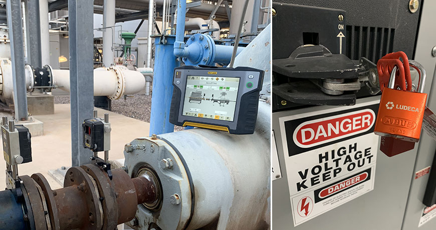
Fortunately, there is a field-proven solution to make sure the baseplate is flat and level. The Easy-Laser XT770G, the complete rotating equipment alignment commissioning package, includes the D22 rotating laser.
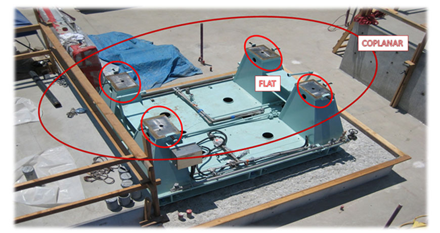
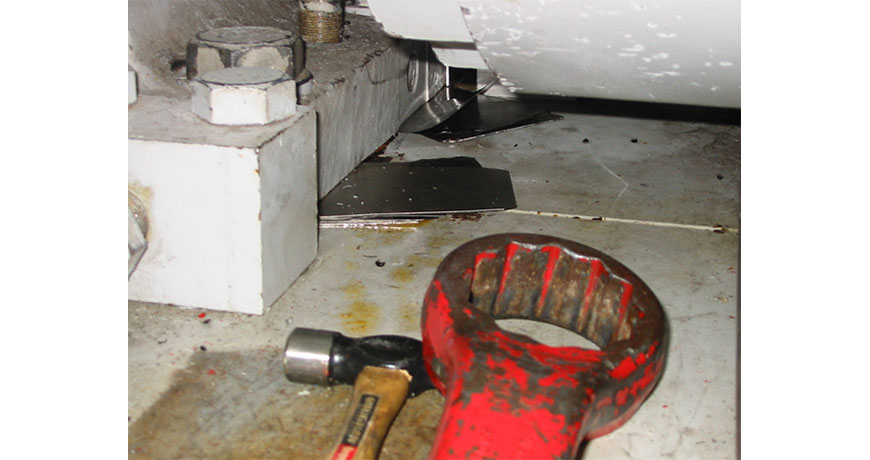
The laser projects a perfect 263-foot laser plane with a detector that has 0.1 mils resolution. This is far greater than the 12” range of the machinist level. In general, this allows the base to be leveled to 0.02 mils/” and coplanar to under 0.5 mils. Machinist levels can’t ensure that surfaces are coplanar, as shown in the photo below:
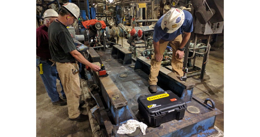
A laser works like a high precision straight edge, allowing for such surfaces to be measured all at once.
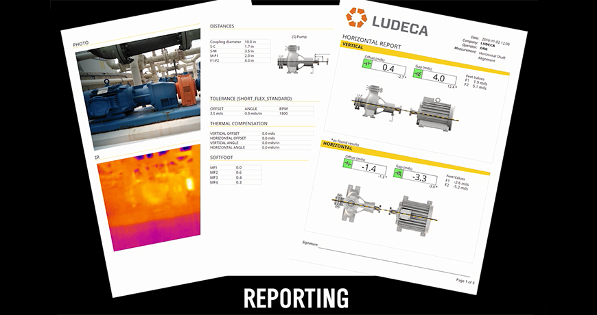
In the same way it has made shaft alignment easy and accurate, flatness and level measurements can also be taken by the same installation crew prior to alignment. The measurements can be taken, flatness corrected and documented using the same computer that will be used for the shaft alignment task.
Our Easy-Laser XT Series is the only laser alignment platform on the market today with the new ANSI alignment tolerances built-in giving the user the freedom to choose between traditional tolerances, the new ANSI standards, or custom tolerances.
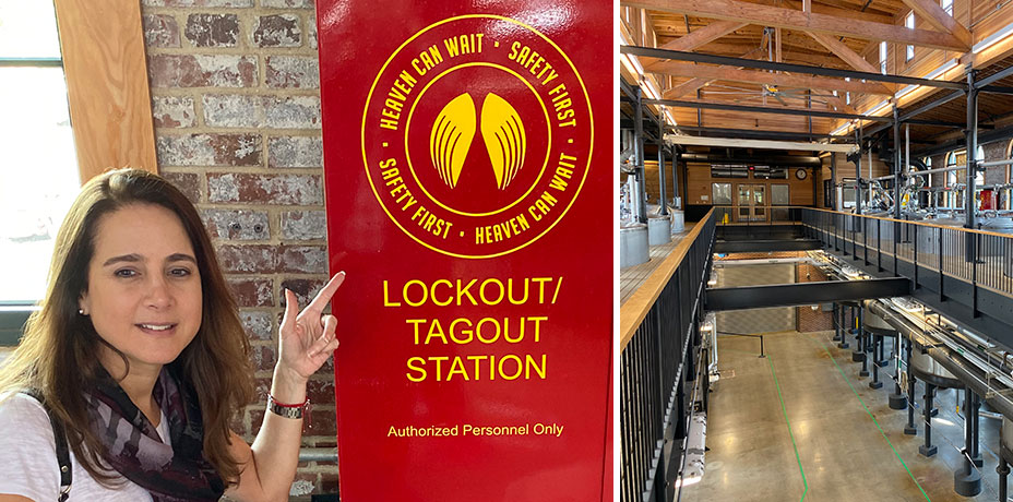
While in Louisville, KY after the #SMRP19 conference, I took a tour of the Angel’s Envy bourbon distillery and was thrilled not only by their fine bourbon finished in port wine barrels but by their attention to safety and unique promotion of safety all around their clean facility. Their clever “Heaven can wait. Safety first” statement obviously applies to all maintenance activities but in this particular case, shown in my photo, it was used to emphasize the importance of lock-out and tag-out procedures, also known throughout our industry as LOTO.
Unlike ultrasound testing, acoustic lubrication or vibration analysis, all of which check machine or facilities condition while up and running, alignment and balancing require machines to be shut down and properly locked out, to adhere to all safety regulations. Only then can the components be mounted on the shafts. This ensures the safe rotation of the shafts and alignment corrections to be made without risk of injury to maintenance personnel.
I can’t stress enough the importance of safety during service or maintenance of machines and encourage you to develop more ingenious slogans like “Heaven can wait. Safety first” to draw more attention to this important concern within your plant.
Here are the six steps to follow for proper LOTO per OSHA 3120:
1. Prepare for shutdown;
2. Shut down the machine;
3. Disconnect or isolate the machine from the energy source(s);
4. Apply the lockout or tag-out device(s) to the energy-isolating device(s);
5. Release, restrain, or otherwise render safe all potential hazardous stored or residual energy. If a possibility exists for reaccumulation of hazardous energy, regularly verify during the service and maintenance that such energy has not reaccumulated to hazardous levels; and,
6. Verify the isolation and deenergization of the machine.
A personal note for Bourbon lovers: if you haven’t already, try pairing dark orange chocolate with your favorite bourbon, what a delicious combination! Heaven can wait. Please drink responsibly.
When you are installing a new machinery in a facility of the organization, there are certain issues. These issues are listed from top to the bottom categorized on the basis of seriousness. The top of the list is shaft alignment. It is the most common issue while installing the machinery. It occurs due to lack of training or of precision instruments, as well as measurement misconceptions. Most organizations think they have achieved alignment just because an instrument showed so. They don’t take the stress and heating mechanisms into account which causes misalignment between the colinear wings of the shaft.
The second issue is the measurement in the base. The machinery installation should start with the removal of stress. The best place to start doing this is by making sure the base is level and flat. You can’t just use any off the shelf leveling tool for that. You need to stick to the height and level measurements from the surface. The third issue is soft-foot. It occurs when one foot of the machine is not in level with the other one. It can cause distortion in the machine casing. It also affects alignment measurements when you are checking for correctness. Download our Soft Foot: Causes, Characteristics and Solutions for the in depth causes and characteristics of soft foot conditions and how to diagnose and solve them
Then comes the pipe strain that causes shaft deflection and case distortion that leads to pump failure. So, you need to avoid putting stress on the pipe. The next one on the list is offline to running. It occurs because of thermal growth in the machine. You can change operating temperature for reducing the initial start-up tork. But there will still be some amount of tork that can lead to this issue. The sixth issue is coupling run-out and machine looseness. It causes vibration in the machine just like misalignment. You can find it out using a dial indicator. You should look for the run-out in coupling and also check the bearings. Watch our Shaft Alignment Know-How video to learn about the effects of running equipment with pipe stress
The number seven is moving the machine. You need to have control when you are moving a machine to avoid sliding. You can use jacking-bolts for that but you need to check the integrity of the bolts as well. You can use the laser to fix this issue or by using graph paper to show how to optimize the machine movement. The next issue is hardware because it makes a lot of difference. Use of poor hardware like nuts, bolts, and key chains can cause machinery issues too. You also need to use proper tools while tightening the bolts and make sure they are calibrated right for the job.
All of this depends on the training because they need to be able to use all the necessary tools. They need to have the proper training. They should be able to do more than just pushing the right buttons. They need to be guided about the proper machinery installation. They should be trained at a standard level for this. The last but not the least thing is to have proper documentation of the quality measures that are taken because it helps you understand the operational phase of the machine.
Thank you James Kovacevic with Eruditio LLC for sharing this [podcast] with us and John Lambert with BENCHMARK PDM for his excellent knowledge on machinery installation!
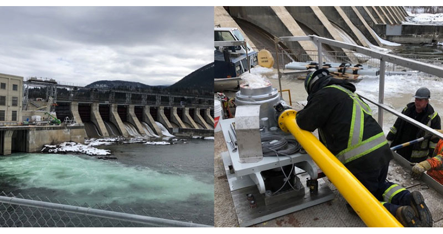
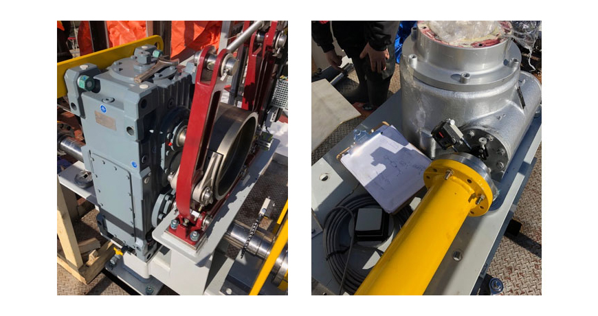
When you are working with nature, you treat it with respect. And that’s what this dam facility on the Kootenay River in British Columbia does (image, above left). When you harness the power of a river you need your control systems to work. The spillway gates control the level of the dam and in this example, it is lifted and lowered by two Worm Drives that are approximately 33 feet apart, so it’s a large gate. Pictured (above right) is one of the worm drives.
The drive motor and gearbox are mounted in the middle and the complete system is being replaced. As with any machinery installation work there will be a lot of alignment work required, including the two drive shafts which are 176 inches in length.
Chad Hansen of CH Mechanical was asked to do the shaft alignment work on the complete drive. Chad owns an EASY LASER XT660 shaft alignment tool which can cover a measurement distance of over 66 feet. He is confident he can do this work however, as the largest span from worm drive to worm drive is 33 feet. But the work doesn’t start on site, it starts back in the shop.
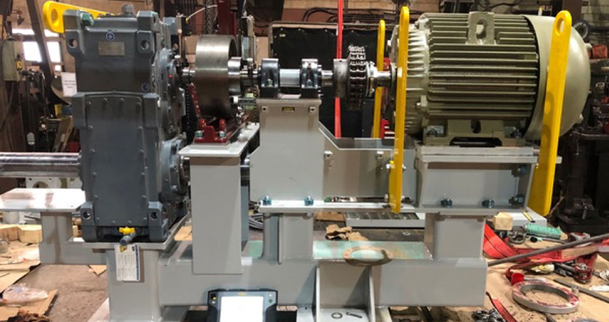
Aligning the Drive Assembly
This is the drive assembly (image below) for the two jackshafts that drive the worm drives, which opens/closes the gate. A new base had been fabricated, which in its self is a nice piece of work! Notice that it has four different levels with machine components attached. That’s 8 mounting foot pads, one for each mounting bolt. Each of these mounting surfaces should be flat. Each set of mounting pads should also be coplanar; for example, the four foot pads for the motor should be flat. I could go on about the importance of base flatness but i’ll leave that for another post!)
Now let’s look at the machine’s components. A good-sized motor with standard mounting feet has a shaft coupled with a chain coupling. This connects to the short spacer shaft supported by two pillow block bearings. This is coupled with a flange-mounted rigid coupling which then connects to a drum brake that is mounted on the gearbox input shaft. Now for the gearbox. The one output shaft is obvious, coming out of the front side of the gearbox (left side of image) with the shaft parallel to the motor shaft. The other shaft is harder to see, on the opposite side, under the drum brake pedestal running underneath the motor. The motor and pillow block base will be removed during the installation but this pre-assemble is to make sure it all fits without being bolt-bound or base-bound.
The most important aspect of this machine’s installation is mounting the gearbox and setting the brake, and that where Chad starts. The gearbox input shaft must be parallel with the mounting surface of the brake. This can be achieved by shimming the gearbox and/or the brake. It’s usually a combination of both to get the optimum move but its time well spent. The end goal is that there is no gearbox shaft deflection when the brake is applied. This means no angle or offset. Next, the spacer shaft is aligned to the gearbox shaft. This is a rigid coupling, so it is best to do this with the coupling open (separated). This is done by using the two built-in electronic inclinometers in the measuring units and either the 9-12-3 measurement method or EasyTurn measurement method. Either way you get a high accuracy, repeatable alignment.
After this you can align the motor to the spacer shaft. With the Easy-Laser XT660 Shaft Alignment tool Chad has different measurement method options because this alignment work is important. Here, he can use the multipoint measurement method and take a series of measurements. He can align the motor to the spacer shaft then go over the top to align the motor to the gearbox shaft, his choice. He can use the new ANSI standard tolerances which is in the display and will be shown in the report.
Installing the Drive Assembly and Aligning the Jackshafts
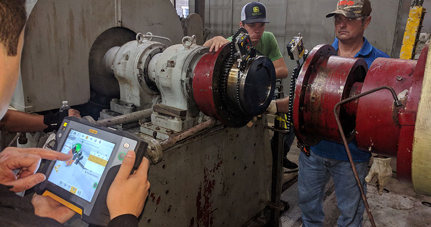
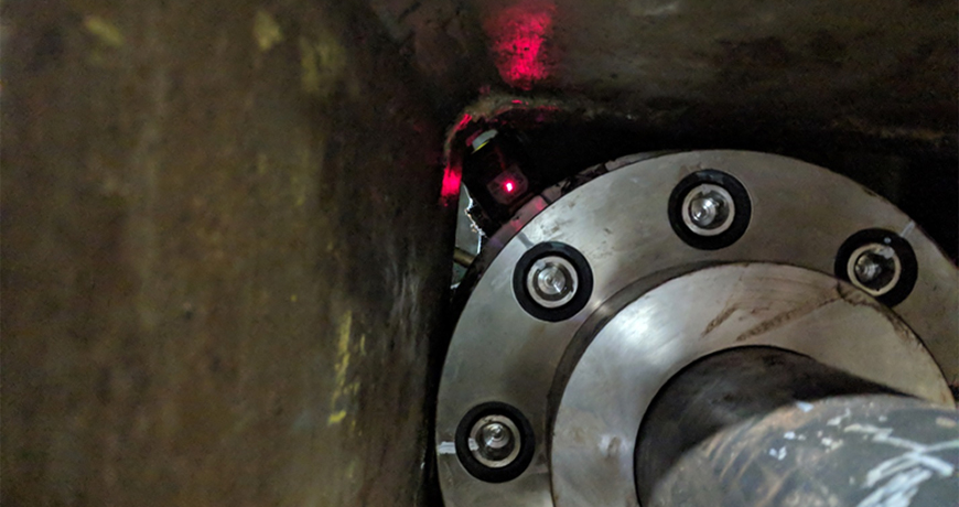
The whole gearbox and drive assembly are installed on site. However, the bearing pedestal, motor, and motor base has been removed for easy access (image, below left).
The right-side jackshaft is installed first, that’s the one closest to the dam. You can see the moveable laser/detector unit mounted on the output shaft just below the drum brake. The worm drive (image, above right) will be the stationary machine with the other laser/detector mounted. The laser alignment data is collected using EASY-LASER’s EasyTurn measurement method with the results showing the amount of misalignment and in which direction they need to move the machine.
The alignment work is completed. There is a little wiggle room at the worm drives however, most of the corrections are made by moving the drive assembly. CH Mechanical uses the new ANSI alignment tolerance for spacer/jackshafts. They are well within spec so it’s a job well done. The actual numbers remain the property of the Dam, so we won’t publish them. However, there is a lot of margin on a 176-inch shaft length. That’s not to say that it’s a quick job, its not. Its actually a very complex job made easy by Chad Hansen and his EASY-LASER XT660 shaft alignment tool.
Thank you John Lambert with Benchmark PDM for sharing this successful story with us!
I remember once performing an alignment where I followed the guidelines at the time to make sure no soft foot was present before continuing the alignment. I struggled to take care of the soft foot issue, yet still had unacceptable results. No more than 3-5 shims under each foot? Check. Pull each shim pack with all feet unbolted and fill in obvious gaps? Check. Inspect shims and remove rusted, damaged or crinkled shims? Ah –hah!
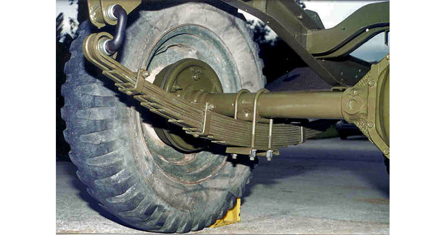
At that point, I inspected the shims and found one, a 150 thou shim, to have a slight bow in it due to it conforming to the base. I essentially had a leaf spring under the foot. No amount of shim corrections will eliminate this situation. A leaf spring is a very common suspension component found in trucks and trailers and shown below.
This leaf spring effect manifests itself in two forms:
The first form is when a very large shim is bent and placed back into the machine foot upside down. This forces the machine foot up when the bolt is loosened during a soft foot check.
The second form is when there are a stack of more than 5 shims, particularly if they are crinkled or bent. The combination of these defects also creates the leaf spring effect.
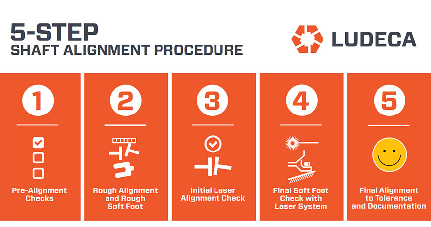
The importance of pre-alignment checks is important in rotating equipment alignment. It is so important that we have incorporated it as step #1 in our standard Ludeca 5-Step Shaft Alignment Procedure as shown below.
The importance of these pre-alignment corrective actions have been incorporated into the ANSI/ASA S2.75-2017 alignment standard. According to the standard:
Shims should be in clean, smooth condition. Used shims should be discarded if the damage is evident. No more than 5 total shims shall be placed under any machine case foot, excluding the shims to correct angle foot conditions. No more than 1 of those shims shall be less than 0.08 mm (0.003 inches) thickness. The sum of the three thinnest shims shall be 0.25 mm (0.010 inches) or greater.”
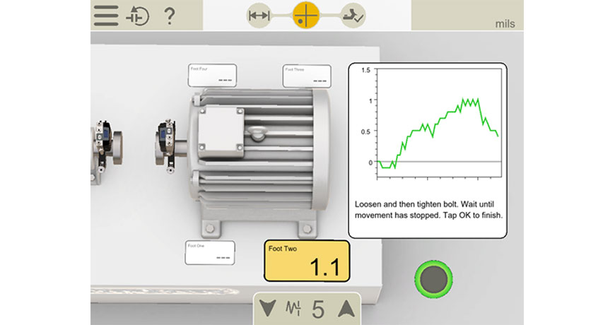
Removing the soft foot issues is important and fortunately, there is a field-proven solution to make sure these have resulted in the problem being remedied and documented. All Easy-Laser E-series and the latest XT-series alignment systems, incorporate a soft foot check program.
Using .0001” resolution detectors, the shaft movement observed when loosening and tightening each foot can be documented for soft foot analysis and correction. With soft foot remedied, the alignment can now proceed with peace of mind knowing the corrections will be more precise and that internal frame distortion of the machine is eliminated.
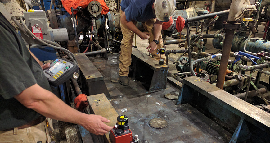
There are many reasons why one would perform an uncoupled alignment. We could have a tight tolerance coupling that cannot be installed without getting the alignment of the shafts close. Or simply, we do not have the coupling available at the moment the alignment needs to happen. Uncoupled alignments are performed using the same 5-step alignment procedure as you would use for coupled alignments. However, there are three differences: how the measurements are taken, how live adjustments are made and how soft foot is checked. Below are some easy-to-follow instructions on how to tackle measurements, live adjustments, and soft foot with Easy-Laser shaft alignment tools:
Alignment Measurement:
Attach measurement unit and brackets to each shaft.
Place the S laser on the stationary machine’s shaft and M laser on the movable machine’s shaft.
Make sure the lasers are at the 12 o’clock position using the lasers’ digital display and the same angle for both S and M lasers are displayed (worst case within 1 degree).
Select the Multipoint measure mode, and take your first point.
Rotate each shaft to the next measurement position of your choosing, making sure the digital display shows the same angle on both S and M lasers (within 1 degree) and take the next point.
Repeat step 5 until the quality of your measurement is above 90%.
Take a second set of measurements to ensure repeatability.
Live Adjustments:
Horizontal live adjustment – rotate the lasers to either the 9 o’clock or 3 o’clock position, making sure the lasers’ digital display shows the same angle for both S and M lasers (within 1 degree).
Vertical it is simply a matter of adding or removing shims. However, to perform a vertical live adjustment rotate the lasers to the 12 o’clock position ensuring the lasers’ digital display shows the same angle for both S and M lasers (within 1 degree).
Go on to the live adjustment screen and perform moves as if the machines were coupled.
Soft Foot Measurement:
After the final alignment measurement, return the lasers to the 12 o’clock position again, ensuring the lasers’ digital display shows the same angle for both S and M laser (within 1 degree).
Access the soft foot measurement screen and check the soft foot as if the machines were coupled.
Watch our 5-Step Shaft Alignment Procedure motion graphic video which outlines an easy and effective way to align your rotating equipment.
We used to assume that once equipment is installed and aligned, it will remain in the same position forever. But this is not always the case.
The alignment should be checked periodically. This valuable information will help you to find problems like pipe stress, unstable foundations, weak frames and loose bolts, among other problems. All the efforts to align your equipment and keep it within tolerance will be worthless if your machinery can’t keep its position. Therefore, the repeatability of the alignment check is your best ally to see how the equipment behaves.
How often should you check?
There are guidelines for how often the alignment should be checked. According to John Piotrowski in his Shaft Alignment Handbook, for newly installed machinery the alignment should be checked after 500 to 2000 hours of intermittent operation, or 1–3 months of continuous operation. If there was no apparent shift in the alignment, then next check should be made at between 4500 and 9000 hours of intermittent operation or 6 months to 1 year of continuous operation. If no apparent shift occurred at any time, then checks should be made every 2–3 years. This interval can of course be influenced by factors such as equipment criticality etc.
If a moderate shift in alignment occurred at any time, then the equipment should be realigned to within acceptable tolerances. If a radical shift occurred, then additional investigation should begin to determine what is causing the shift – a root cause analysis. For example, any indication of excessive wear and tear will also be an indicator of a “non-healthy” machinery installation.
The importance of documentation.
To have properly documented alignment checks is essential to avoid repeating the same installation errors, or to discover and follow up on recurring problems. Of course, there is no exact answer to the headline question. But the documentation will give you a very good understanding of what happens along the way, and help you keep your machinery aligned as long as possible.
Thank you Roman Megela with Easy-Laser for sharing this informative article with us!
We previously discussed the Types of Misalignment and Types of Soft Foot as causes of machine failures. In this blog, we will discuss Pipe Strain and how it can result in misalignment and vibration.
Pipe strain is a form of machine frame distortion caused by the piping as opposed to feet or base condition. The forces from the pipes are transferred through the driven machine onto the driver machine causing vibration and misalignment at the coupling. Sometimes the forces are not great enough to transfer onto the driver, but will affect the internal misalignment of the driven machine and therefore cause premature failure. Here are a few causes of pipe strain:
A shift in the foundation
Incorrect pipe fitting
Thermal expansion of the pipes
Broken, improper, or lack of hangers and wall mounting hardware
Checking and correcting pipe strain in all alignment jobs will eliminate these forces allowing the machines to run properly.
Watch our Shaft Alignment Know-How video to learn about the effects of running equipment with pipe stress
We previously discussed the Types of Misalignment as a cause of machine failures. In this blog, we will discuss Types of Soft Foot and their impact on machines.
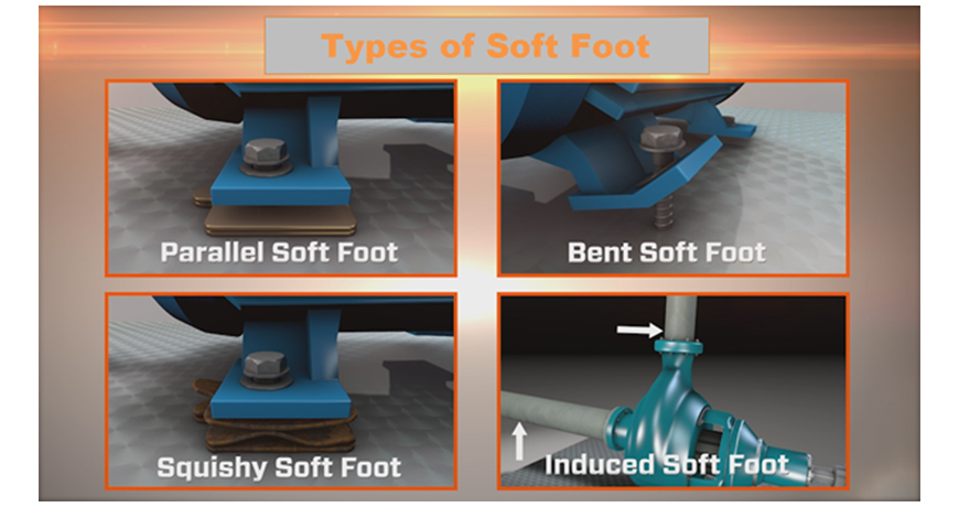
Soft foot means machine frame distortion that occurs when the machine hold-down bolts are loosened or tightened. A soft foot condition can lead to internal misalignment of the machine which will add unwanted loads and forces to the bearings. Soft foot will also deflect the shaft as it accommodates the internal misalignment of the frame of the machine. There are four main types of soft foot:
Parallel soft foot: Occurs when one of the feet on the machine does not touch the base while the other three do. This creates a parallel gap between the foot and the base when that foot is loosened.
Bent soft foot: Occurs when a foot of the machine is deflected or in an angle with regard to the base. However, this also applies to when the base is in an angle with respect to the foot.
Squishy soft foot: Occurs when too many shims are used under the foot. Shims create an accordion effect causing the foot to lift off the ground even when there is no soft foot.
Induced soft foot: Occurs when external forces such as piping or electrical conduit pull or push on the machine creating a distortion of the frame.
Soft foot needs to be checked and corrected to within 2.0 thousand of an inch to allow the machine’s frame to run free from distortion.
Watch our Shaft Alignment Know-How video to learn about the effects and importance of measuring and correcting Soft Foot when performing shaft alignment.
Misalignment occurs when the driver’s (motor) shaft centerline of rotation is not concentric with the driven shaft’s (pump) centerline of rotation. Even today some professionals assume that the coupling will deal with the misalignment. However, the misalignment tolerance built into the couplings merely show how much misalignment the coupling can handle and still transfer power. They are not designed to magically make machine misalignment disappear. The shaft misalignment will transmit critical loads and forces along the shafts creating high vibration and premature wear on both the driver and driven machine. Misalignment happens in both the vertical and horizontal planes and is identified as:
Offset: The distance between the two shafts’ centerlines at any point along their centerlines, also known as parallel misalignment.
Angularity: The angle or rate of change of the offset between the two shafts’ centerlines, also known as gap difference over the coupling diameter, or Rise/Run.
Watch our Shaft Alignment Know-How video to learn about the concepts of Offset & Angularity as they relate to aligning rotating equipment
To ensure your machines run reliably, misalignment needs be checked and corrected to the tolerances provided by the facility or machinery manufacturer.
Watch our Shaft Alignment Know-How video to learn the causes and effects of having misalignment in your rotating equipment
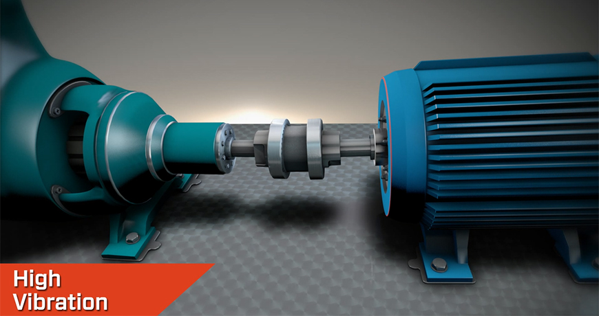
Vibration is everywhere! Vibration is a “back and forth” movement of a structure or component. Vibration can also be referred to as a “cyclical” movement. It can be inherent in a piece of equipment or can be induced by another form of energy. The real question is whether the vibration is detrimental to the equipment and its internal components.
Vibration is typically monitored through some form of analyzer, either online or offline such as the VIBWORKS analyzer.
What causes vibration? Here are just a few causes, but there are so more which can lead to elevated vibration levels. More importantly, if caught early enough, they can be corrected and thereby maximize the life of our equipment:
Installation of the machines
An improperly mounted bearing can cause severe vibration. This can lead to damage of the bearing as well as other components within the machine.
Operation of the machine
Pushing our machine beyond its recommended maximum output. Our machines respond by vibrating more than the recommended allowable limits and will eventually fail.
Watch our video ‘What’s Misalignment’ to learn more about the causes and effects of having misalignment in your rotating equipment
Some common machine problems that generate mechanical vibration:
Misalignment
Misalignment is one of the most common issues that leads to high vibration and eventually failure of the machine. It can be easily detected and corrected. Take the time to laser align machines properly to the recommended tolerance.
Unbalance
Unbalance is another easily missed problem that causes severe damage to our equipment. It can also lead to cracks of the housing itself. If not detected and corrected soon enough it can lead to dangerous catastrophic failure. Unbalance can be easily detected and corrected extending the life of the equipment.
We never have enough time to do things right the first time but always find time to do them again.”
These few issues can be easily detected with properly set-up software. Often, the setup is incorrect and inaccurate. Invalid data is captured in the FFT. Please consult an expert to make certain you are utilizing your condition monitoring software to its fullest potential. Remember… If it’s Critical and Rotates it should be Aligned, Balanced, and Monitored.
A couple of months ago, we were hired to perform an alignment on a motor/gearbox setup with a 9-foot spacer coupling in between. The obstacle this time around was that the spacer coupling was going through a steel support beam. The coupling is round but the hole in the beam was square, just big enough for the coupling to go through. With a circle going through a square, only the corners of the hole were open. This meant that line-of-sight between the two lasers was limited. Because of the obstruction there was no way to obtain data with a continuous reading. Using our dual-laser XT660 system, we decided to take readings in each available corner. We could have taken one point at each 45 degree position. However, taking more points is always beneficial. We decided to take three points (close together) in each of the corners. With two rotations, we obtained excellent repeatability. Once we had repeatable readings, we moved the machine according to the calculated alignment results and aligned it to our customer’s customized tolerances.
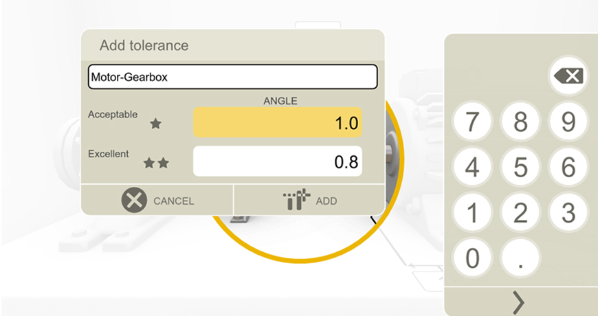
Many times we are faced with awkward alignment situations. It is helpful to have an alignment tool that is very easy to use, yet versatile to adapt to these situations. It helped that the Easy-Laser® XT660 allowed us to change measurement modes (in this case to Multipoint mode). It also helped that the tool allowed us to adjust our tolerances to the customer’s particular needs. The customer did not want to use the built-in Easy-Laser tolerances, nor the ANSI standard tolerances that are included in the system. Instead, they were looking to align the machines to within 0.1 thou/inch (or 1.0 thou/10 inches) of angular misalignment at each flex plane. So we created a custom tolerance instantaneously within the tool for this job. The customer was satisfied with the alignment and the report generated with their tolerances.
When it comes to shaft alignment, experts from industrial service provider Bilfinger have relied on the co-operation with Swedish company Easy-Laser for nearly two decades. Now, the company is introducing a new generation of devices, which will greatly simplify the alignment process for clients and employees, especially in potentially explosive environments.
Maintenance Personnel at Bilfinger Maintenance in Höchst have been using laser-based measurement and alignment systems from Easy-Laser since 2001.
In addition to cost factors, the main deciding factor in our collaboration with Easy-Laser was their user interface, which is easy to understand and, there-fore, very user-friendly, explained Karl-Heinz Bank, head of Machine Technology and Service Technicians at Bilfinger Maintenance in Höchst.
In spring this year, the good working relationship strengthened further. After Easy-Laser had officially launched their XT550 EX shaft alignment system at the Hannover trade show, the innovative measurement system was delivered to Bilfinger, who was the first customer.
Without doubt, the old systems that had been in use for a long time were still reliable, as confirmed by Mr. Jurgen Rabe, Head of Pump and Engine Technology at Bilfinger in Höchst. However, the industry had been waiting with great anticipation for a new shaft alignment system.
MYTH: “You should always do your shimming first and then make your horizontal moves.”
TRUTH: This is generally true for the final alignment after soft foot has been corrected, but is not universally true for all alignments. In fact, for the initial rough alignment you should correct the plane with the largest misalignment first, even if this means making a horizontal move first. Reason: If you have gross misalignment, you could be binding the coupling, deflecting the shafts and imposing undue load on the bearings. By relieving strain from excess misalignment, a truer picture of the alignment condition emerges, and you eliminate an important outside force that creates machine frame distortion (soft foot). Therefore, the correct sequence of events in any alignment job is:
The recently released Alignment Standard (ANSI/ASA S2.75-2017) from the American National Standards Institute, Washington (ansi.org) took nearly three years to develop. A committee of alignment experts discussed every aspect from safety procedures to the mathematics involved in defining the new standard. Alan Luedeking, CMRP, CRL, of Ludeca Inc., Miami (ludeca.com) a member of that committee, has been involved in the development of alignment standards for significantly longer than three years.
Luedeking remembers the “old days” well. Back then, personnel simply aligned components to the best of their abilities with straightedges or dial indicators. “Those alignments,” he said, “usually weren’t that good, due to sag, span limitations, obstructions to rotation, or whatever. But you did the best you could, and that was good enough because it was all you could do.”
In 1982, Ludeca introduced the world’s first computerized dial indicator alignment system (from the now-defunct Industrial Maintenance Systems Inc.), followed in 1984 by the world’s first laser-alignment system. With the improved measurement resolution and accuracy afforded by the laser sensor, a more precise definition of what constituted a good alignment became necessary. So, according to Luedeking, after poring through the sparse alignment literature that existed, Ludeca developed tolerance tables for short and spacer couplings, which, for lack of anything better, end users readily accepted. “Over time,” he noted, “these tolerance values came to be accepted as the U.S. industry standard and were adopted as the official tolerance standard by various corporate and government entities, including NASA and the U.S. Navy.”
So what are alignment tolerances, and why are they important? As Luedeking described them, “Tolerances exist because absolute perfection does not. No matter how hard you try and how long you work, you will never get a shaft alignment absolutely perfect.” He offered the following detailed discussion as to why, along with some expert advice on the meaning of the new standard and how it can help you improve your operations. Read the entire article “Alignment Tolerances Carved in Stone”
Check out the Easy-Laser XT Series, the only laser alignment platform on the market today with the new ANSI alignment tolerances built-in giving the user the freedom to choose between traditional tolerances, the new ANSI standards, or custom tolerances of the user’s own choosing.
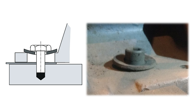
Often, maintenance departments invest in good quality Bolts and Nuts (Grade 8), but neglect to do the same with flat washers. The importance of a good washer cannot be overstated. If you use a typically thin Grade 2 (or worse) flat washer under the bolt head of the hold-down bolts of your machine, this washer will easily be distorted or warped into the hole in the foot upon tightening the anchor bolt. This is particularly true if the difference in shank diameter of the bolt and hole diameter in the foot is significant. This will often be the case when the hole in the foot has been enlarged to overcome a bolt-bound problem. The result of having “dished” washers is that when the anchor bolts are tightened after completing the alignment, the washers will try to center themselves in the hole in the foot and in doing so will pull your machine out of alignment again. This effect is virtually impossible to overcome, resulting in a badly misaligned machine after you just did a good alignment!
Solution: Always discard warped washers and use high quality thick flat washers that will not distort or warp into the hole. This will allow the washers to do their job of supporting the bolt head’s load on the surface of the foot.
MYTH: “All Soft Foot can be corrected by proper shimming.”
TRUTH: Soft Foot is Machine Frame Distortion. This can sometimes be caused by problems not easily fixable by shimming, like pipe strain, which can only be properly corrected by adjusting the piping and interface with the machine. A good laser system with positional change monitoring capability (such as EASY-LASER XT770 with Easy-Trend) is the best way to detect and measure the effects of pipe strain.
MYTH: “Pipe Stress makes the alignment difficult.”
TRUTH: Pipe stress does not have any significant influence on the alignment unless you make corrections on the machine with the piping attached. In most alignment, the corrections to eliminate misalignment are performed on one machine only, typically the one that is easier to move. In a pump-motor set, the corrections are done on the motor. If there is sufficient room to shim and move, excellent alignment can be achieved regardless of how much pipe stress there is on the pump. Of course, pipe stress is undesirable and should be eliminated prior to the alignment.
We often hear “Coupling alignment tolerances provided by the coupling manufacturer are good enough for shaft alignment.” or “There’s no need to align your machines tighter than the tolerances allowed by your flexible coupling.”
This is wrong because good quality flexible couplings may be built to withstand much more misalignment than what is good for your connected machines, in terms of the vibration and other forces created. Bearings and seals may wear out and fail faster than a highly misalignment-tolerant coupling. The reason for this “extra misalignment capacity” in flex couplings is that they may need to withstand significant positional changes resulting from thermal growth or dynamic load shifts. This lets you deliberately misalign machines to “cold alignment” targets.
 If you have two equally hard-to-move machines, each of which you would ordinarily like to consider stationary (such as a heavily piped little steam turbine driving a heavily piped compressor), then it really just boils down to which machine (or combination of feet on both machines) is the most expedient to move. Just mount the “S” laser on the on the left as usual. You can always use the lock feet function to declare the machine on the right stationary and make the machine on the left movable, or ask the tool to make any combination of feet movable so as to find your smallest possible moves or optimal combination of moves to solve bolt-bound or base-bound situations in the field. The Easy-Laser XT products are especially versatile for this, since they let you explore fully optimized centerlines (move ALL the feet in the train), as well as under-constrained and over-constrained centerlines, to cope with the exigencies of the situations you encounter in the field.
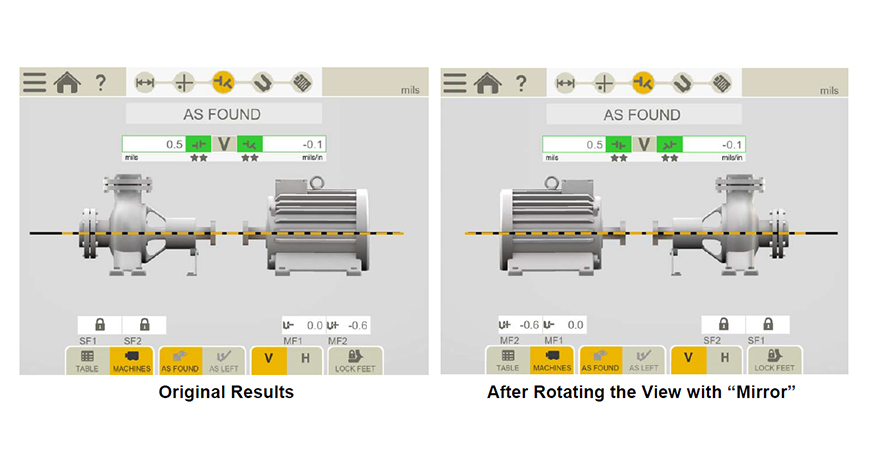
 The right-side jackshaft is installed first, that’s the one closest to the dam. You can see the moveable laser/detector unit mounted on the output shaft just below the drum brake. The worm drive (image, above right) will be the stationary machine with the other laser/detector mounted. The laser alignment data is collected using EASY-LASER’s EasyTurn measurement method with the results showing the amount of misalignment and in which direction they need to move the machine.
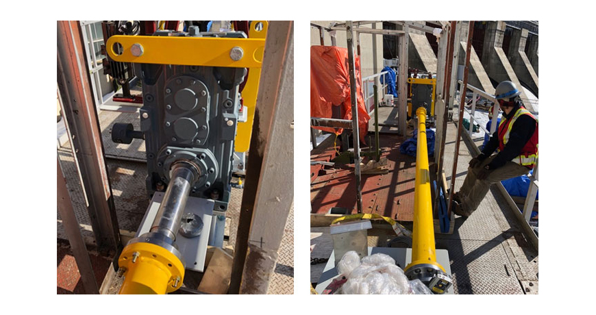


 Often, maintenance departments invest in good quality Bolts and Nuts (Grade 8), but neglect to do the same with flat washers. The importance of a good washer cannot be overstated. If you use a typically thin Grade 2 (or worse) flat washer under the bolt head of the hold-down bolts of your machine, this washer will easily be distorted or warped into the hole in the foot upon tightening the anchor bolt. This is particularly true if the difference in shank diameter of the bolt and hole diameter in the foot is significant. This will often be the case when the hole in the foot has been enlarged to overcome a bolt-bound problem. The result of having “dished” washers is that when the anchor bolts are tightened after completing the alignment, the washers will try to center themselves in the hole in the foot and in doing so will pull your machine out of alignment again. This effect is virtually impossible to overcome, resulting in a badly misaligned machine after you just did a good alignment!