We often hear “Coupling alignment tolerances provided by the coupling manufacturer are good enough for shaft alignment.” or “There’s no need to align your machines tighter than the tolerances allowed by your flexible coupling.”
This is wrong because good quality flexible couplings may be built to withstand much more misalignment than what is good for your connected machines, in terms of the vibration and other forces created. Bearings and seals may wear out and fail faster than a highly misalignment-tolerant coupling. The reason for this “extra misalignment capacity” in flex couplings is that they may need to withstand significant positional changes resulting from thermal growth or dynamic load shifts. This lets you deliberately misalign machines to “cold alignment” targets.
Take a look at our Shaft Alignment Tools
by Yolanda Lopez
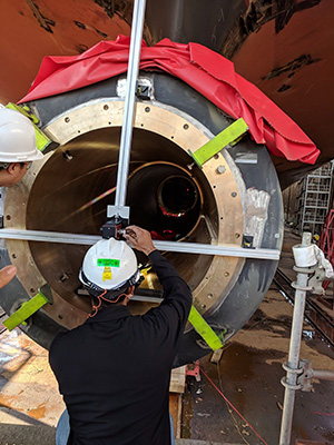
We just returned from performing a stern tube bearing carrier alignment on a large container vessel currently in construction at a leading US shipyard. The one-meter diameter bearing carriers needed to be set to specific tolerances with respect to an established datum line along the longitudinal axis of the ship. Historically, this was accomplished using optics, piano wire and depth gauges. The procedure was time consuming and considering the sizes of some of the vessels being fabricated, performing an alignment was tedious and time consuming work. Sunlight on the hull can cause considerable movement; therefore a faster alignment process would be desirable. Therefore, we were asked to bring in the Easy-Laser E950-B bore alignment system. The quick setup and operation of this wireless laser alignment system made taking bore straightness readings a breeze, saving valuable time on a warm sunny morning in dry dock. The client was pleased with the speed with which the job was performed and the ease of understanding results—a testament to the straightforward design of the E-Series software.
by Yolanda Lopez
Reposted from People and Processes, written by Jeff Shiver CMRP, CPMM, CRL
Do you find yourself wondering why your employees haven’t taken the initiative and approached you for additional training? Well, they must not want the extra training, right? Wrong! Sometimes, employees do want training, but they just don’t ask. Here’s why:
1. THEY HAVE FEAR OF REJECTION
People don’t like to be told no! The majority of employees don’t understand the organization’s vision, goals, brand promise, or key initiatives.
2. THEY FEEL UNSUPPORTED
Employees get worn out from a culture of mediocrity being tolerated, commitments not honored, and requests being ignored.
3. THEY DON’T KNOW HOW TO ASK
Operators, Mechanics, Planners, and even Managers may not understand how to equate the returns of training.
4. THEY DON’T KNOW WHEN TO ASK
Many employees don’t know when there is flexibility within the budget.
5. THEY ARE AFRAID OF BEING NEEDY
If no one else is asking for training, then why should they expect to be treated differently?
6. THEY FEEL AWKWARD OR UNCOMFORTABLE
There must be a commitment for development and the line of communication should be open.
7. THEY DON’T FEEL CHALLENGED
They may be topped out and let with nowhere to go from a promotional perspective.
8. THEY DON’T KNOW WHAT THEY DON’T KNOW
When people have never been exposed to anything else, they don’t know what else is possible.
Keep these things in mind the next time you offer training, or feel that your employees should ask you if they want it. A better approach may be discussing this with your employees individually.
Check out LUDECA training offering for alignment, geometric measurements, vibration analysis, balancing and ultrasound.
by Ana Maria Delgado, CRL
Guest Post by Ricky Smith, CRL, CMRP, CMRT
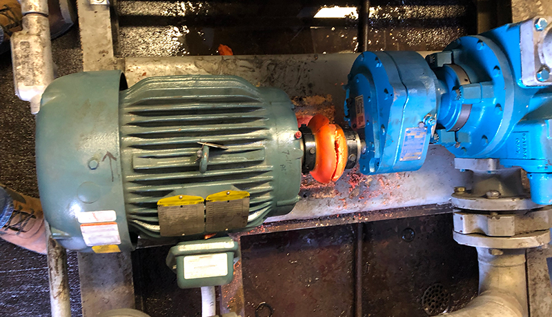
Pipe stress is caused by misalignment of the mating surfaces of two pipe flanges creating abnormal internal stress of pump bearings, seals, motor bearings, and couplings, and can possibly change the displacement of a pump.

General Rules which must be followed by maintenance personnel and contractors: (if you truly want to stop a long term pump problem)
- Pipe flanges attached to pumps must be aligned where the gap does not exceed the thickness of two gaskets or the tolerance established by your company’s engineering standards.
- Pipe flange bolts must drop in without assistance.
- Cable pullers, come-a-longs, or long bars should not be used when aligning a flange that is connected to a pump.
- Validate the elimination of pipe stress by following the guidelines listed below.
Failure Modes experienced from Pipe Stress on Bearings:
- Wear caused by seals leaking
- Wear caused by static vibration
- Indentations caused by overloading while static
- Corrosion caused by inadequate lubrication caused by abnormal loading (seal leaking)
- Flaking caused by misalignment and excessive loading
WARNING: Ensure your contractors follow the same process to eliminate pipe stress. Pipe stress elimination should be validated during the commissioning of a new pump.
Follow this process if you want to inspect your pumps that may have pipe stress:
- Align the two shafts between your pump and driver (typically an electric motor) to the tolerance recommended by the equipment vendor or your company’s engineering standards.
- Validate misalignment to insure motor and pump shafts are aligned to specification.
- Disconnect the outlet flange on the pump.
- Revalidate laser alignment of shafts.
- If alignment has moved then you have pipe stress. Do the same for the inlet flange.
- Make corrections as stated in the following procedures to eliminate pipe stress.
Elimination of Pipe Stress – “The Ricky Smith Method for Pipe Stress” as learned from Dan Turner (his maintenance and engineering manager at Exxon during his career in the 1970s)
- Bolt flanges to pump and insert blind flange gasket along with two regular flanges between pump and mating flanges (cover the hole between the welding area and inside the pump).
- Attached welding ground to flange. (do not attach ground lead to pump; welding group must always be attached to flange) WARNING: Failure to accomplish this one task properly will cause bearing failure by “electric arcing” which is a failure mode of bearings.
- Tack weld flange into place reverse welding each tack.
- Allow cooling for 10 minutes.
- Reverse stitch weld on opposite sides on the flange is similarly used for cast iron welding.
- After initial reverse stitch weld then weld normally using electrode recommended by the American Welding Society (typically E-6010 5P or GTAW)
- After root pass; weld in any direction you wish.
- Allow to cool and then disconnect flange, replace gaskets and;
Validate bolts will drop into holes without a pry bar.
Validate gap between flanges is no more than two gaskets thick.
To learn more about the effects of running equipment with pipe stress, watch the LUDECA Shaft Alignment Know-How Pipe Stress tutorial video.
by Yolanda Lopez
Guest Post by Bob Dunn from I&E Central, Inc.
I had the opportunity to use the Easy-Laser XT440 to assist a customer in aligning a machine that had perpetually given them problems, with bearings always running hot. They had recently aligned the machine with dial indicators, but when we checked, it was off by .007, and this was on a 3600 RPM motor. We removed their old shims and did a soft foot check indicating .032 under one of the feet. Further inspection showed an angular gap under one foot. It turns out that when new, someone had ground down the feet on the motor to better align to the pump – obviously not a precision job. We step-shimmed to fill the angular gap, then aligned the machine in a single move. Several of the techniques we used were unfamiliar to these mechanics.
Takeaways:
- Do your pre-alignment homework to detect and correct foundation issues.
- Be sure mechanics are really trained in alignment – not just how to push the buttons. By the way, Ludeca Inc. and I&E Central provide excellent training.
- The Easy-Laser XT-Series is a fast, accurate, and incredibly easy-to-use tool for coupling alignment and more. If you use something else, you should see what you are missing!
by Ana Maria Delgado, CRL
As Published by Solutions Magazine March/April 2018 issue
by Ana Maria Delgado, CRL and Shon Isenhour, CMRP CAMA CCMP, Founding Partner at Eruditio LLC

During the many root cause analysis (RCA) investigations we facilitate and coach, we notice some themes that continue to manifest themselves in the findings. Often, they are grouped under the heading of precision maintenance or lack thereof. Let’s take a look at some of them and determine if they are also killing your reliability.
The six killers are grouped into three areas: Lubrication, Misalignment, and Undiagnosed Wear.
Click here to read the full article.
by Ana Maria Delgado, CRL
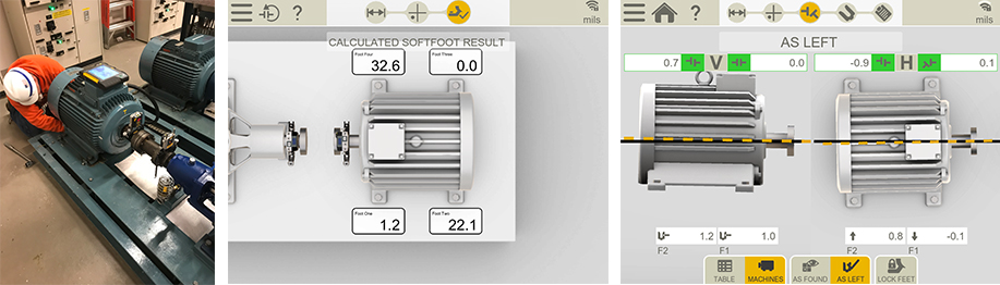
In the 35+ years of experience that LUDECA has in shaft alignment, we have been asked this question many times. How long does it take to do an alignment? People in charge of scheduling have a tough task when allotting time for technicians to do an alignment with precision. In many cases, they may just take a guess, based on the average time it has taken in the past. The answer is not so simple. During a one-day seminar, I had to perform an alignment on a motor to a pump to show the proper steps when aligning a machine. When the time came to start the alignment, all the safety procedures had been taken care of, and the machine had been rough aligned. The soft foot values were within tolerances. So I was able to align the machine in under 45 minutes, within the tolerances specified for 1200 RPM.
On another occasion, I was hired to help align a generator to a turbine. Quite a few things went right as well. The safety procedures had been taken care of by the time I got there. The coupling guard and coupling element had been removed. The machine had also been rough aligned. The special-order shims for the generator feet were available on-site. Even with all these things going my way, this alignment took a day and a half to finish. There are things that come up during an alignment that cannot be planned for. One of them is a soft foot condition. Not checking for soft foot can greatly increase the time it takes to align a machine, mainly because the response to corrections stipulated by your alignment tool will not be accurate. Therefore, knowing the soft foot condition and minimizing it, is key. However, that in itself can take up a long time, depending on the condition of the baseplate, the condition of the anchor bolts, washer, pipe stress, etc.
In both cases, they were a single coupling alignment. Aligning a large generator is obviously more difficult than a 200HP motor. In the first case, I was able to turn the motor with a strap wrench by myself. In the case of the generator, it needed to be uncoupled because the two machines could not be turned together. In most cases, a larger machine takes longer to align because breaking the bolts loose, alone, could take 20 to 30 minutes. Furthermore, there can be a large difference in the amount of time it takes to finish an alignment, between two identical machine sets. The information obtained here can help reduce the alignment time.
I recommend downloading our 5-Step Shaft Alignment Procedure and/or requesting our Shaft Alignment Fundamentals Wallchart for your alignment team. The point is that there is no fixed amount of time required for an alignment of a machine. If a scheduler should err, it should always be on the conservative side.
by Adam Stredel CRL
Reposted from Easy-Laser®
The latest addition to Generation XT, Easy-Laser® XT660, gives you access to four different measurement methods for shaft alignment. Each with its own advantages. Read more to find out how to use them best!
The four measurement methods are 9-12-3, EasyTurn™, Multipoint, and Continuous sweep. Here we describe them individually so that you know when best to use them.
Method 1: 9-12-3
The clock method, or 9-12-3 as it is also known, is the origin of all shaft alignment. Anyone who knows how to use analog dial indicators will recognize this method. A dial gauge is mounted on each shaft, and the measurement values are taken at three different points, corresponding to the 9-12-3 positions on a clock, or the angles 0-90-180 of a circle. It is based on geometry (and trigonometry), more specifically circle mathematics. The mathematical assumption is that if we can measure the semicircle, we can then work out what the whole circle will look like, and consequently determine the center of the circle (rotational center) for both shafts. These centers can then be compared to each other and we can thus work out how well-aligned the machines are to each other. And with a laser-based measurement system, also obtain direct feedback from the adjustment of the machine in real-time.
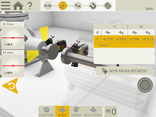
When should this method be used? One answer is that this method can always be used when you are able to rotate the shafts freely, and there are no other physical obstructions preventing you from measuring from the 9-12-3 positions. However, the restriction is that you must position the measurement devices at 9-12-3 as accurately as possible and that the system does not use the built-in inclinometers to calculate the position (in other words, you must check this yourself).
There is, however, one application when you must use the 9-12-3 method; during shaft alignment on-board seafaring vessels. This is because the inclinometers would move in conjunction with the vessel’s movements on the waves, potentially corrupting the collected measurement values. We, therefore, recommend using the 9-12-3 method as the inclinometers are switched off.
Method 2: EasyTurn
EasyTurn is a unique further development of the 9-12-3 method, with the freedom to choose at which clock position (which angle) you start collecting measurement values. With the help of some mathematics, we can also restrict the total measurement range to 40 degrees full rotation. From a practical point of view, this means that you can use this method where there is limited possibility of rotating the machines, due to the lack of space around the shafts.
This method is the standard-setting in most Easy-Laser shaft alignment systems (except XT660, which uses ”Continuous Sweep” as the standard method, see below).

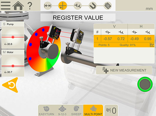
Method 3: Multipoint
Multipoint is, in turn, further development of EasyTurn. Multipoint also means that you can start collecting measurement values from any clock position (angle), and complete collection across as small a rotation as 40 degrees. However, as the name suggests, this method means that values are collected from more than three points.
This is advantageous if taking measurements from larger machines where it is difficult to rotate the shafts. Collect the measurement values across a shorter rotation to increase the mathematical probability of obtaining good measurement values. This method also gives a quality evaluation of the measurement series. The evaluation takes into account shifts in temperature, measurement direction, and a number of measuring points.
Method 4: Continuous Sweep
Continuous sweep can be described as Multipoint with automatic, continuous measurement value collection. In practice, this means that you can collect measurement values continuously with the measurement devices in motion. I.e. you start measurement value collection (at any clock position/angle) and then rotate the shafts without stopping, in one direction. Continue until you have collected enough measurement values to achieve a good quality calculation (quality evaluation is also performed here just as in Multipoint).
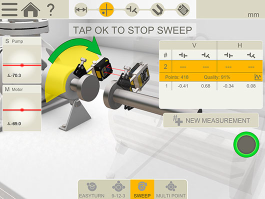
In the end, the shafts’ rotational center is calculated and presented graphically via images and text. This method is very useful in instances where it is difficult to stop the machines to take stationary measuring points, for example, when aligning large turbines.
We hope you now have a clearer picture of the various measurement methods and when best to use them.
The Easy-Laser XT Alignment App can be downloaded free of charge from the App Store and Google Play to try out.
by Ana Maria Delgado, CRL

We at LUDECA proudly share the excitement with our partners at Easy-Laser® for winning the Red Dot Design Award 2018 with their XT11 display unit.
The distinctive Red Dot is established internationally as one of the most sought-after quality marks for good design. Here are some of the things they considered in their evaluation:
• Degree of innovation
• Functionality
• Formal quality
• Ergonomics
• Durability
And yes, this is their second design award with the excellent development and capabilities of the XT11 display unit. They won the iF Design Award in 2017. XT11 has some smart functions, like the screen-lock button which prevents unintentional clicks on the touch screen when you move around the machine you measure. As an option, you can fit your XT11 with a thermal imaging camera, opening up even more possibilities to optimize your machinery for smooth operation.
Easy-Laser XT11 runs the XT Alignment app, which can also be run on iOS and Android phones and tablets. This is a unique feature in the alignment industry – the user can combine display units and different types of measuring units to suit their needs and budget – but will only have to learn one alignment program!
Congratulations to our partners at Easy-Laser for winning this great award for this excellent product!
Contact us if you would like to see the Easy-Laser XT11 display unit in action or watch the XT11 video.
by Ana Maria Delgado, CRL
An arc-second is a measurement unit for angle. It is often used in describing level and plumb.
1 arc second = 1/3600 degree = 0.000278 degree =0.0000048 inches/inch =0.0048 mils/inch = 0.0048 mm/m
1 degree = 17.347 mils/inch
1 mil/inch = 1 thou/inch = 1 mm/m (The metric-imperial relationship is purely a coincidence!)
A high accuracy machinist bubble level, a commonly used tool to check the level of baseplates and foundations, is typically 0.24 mils/foot (often mentioned as a “quarter of a thou per foot” in the field) = 0.02 mils/inch = 4.15 arc seconds.
by Daus Studenberg CRL
“Mil” and “thou” are the same. They are imperial measurements both are synonyms for 0.001 inches. This unit is normally referred to as a “thou” (which is short for a thousandth), or (particularly in the United States) a mil. Mil has its origins in the metric prefix “milli”, which is Latin for “one-thousandths”. The plural of a mil is mils and the plural of thou is thou.
by Daus Studenberg CRL
In rotating equipment installations, there are many tools employed by the concrete pouring team, the baseplate fabricator, the rotating equipment installer, the pipefitter, the alignment team, etc., to get the job done as effectively and efficiently as possible. “Square, plumb, level, and true” is what allows those teams to work together. “True” means something is exact or accurate. In rotating machinery, true can encompass how accurately equipment is aligned, in flatness, straightness, or rotational centerline (coupling) alignment.
Cutting corners in square, plumb, level and true is non-negotiable. If one team does not hold to this principle, it can cause significant problems for the rest of the teams in the form of delays involved in having to work around and remedy the alignment problem. We’ve heard the stories of machinery installations that have bolt-bound issues, pipes that don’t fit, and baseplates that are warped, many resulting in a need for extreme soft-foot corrections.
These are all symptoms of some part of the installation not holding to square, plumb, level, and true. When all teams abide by this principle of square, plumb, level, and true, the installation will be more efficient, have fewer delays and ensure that no costly rework will be needed to undo incorrect installation.

by Daus Studenberg CRL
Condition Monitoring Expert Tip #9 by Mobius Institute
No, sadly, that may not be correct. If the spectrum (and phase readings) indicate misalignment, then the machine will be misaligned. But if there is no indication of misalignment, the machine may still be misaligned. I know that may not make sense, but unfortunately, it is true.
A number of experiments have been performed where real machines were misaligned and the vibration pattern did not change. The vibration pattern depended upon the type of coupling and other conditions, but the bottom line is that the only way you can be sure that the machine is precision aligned is to precision align the machine with a laser alignment tool.
We appreciate Mobius Institute for allowing us to share this tip with you!
by Ana Maria Delgado, CRL
Belt alignment is extremely important, and we recommend you do it with a good laser alignment system such as the Easy-Laser XT190 or the DotLine Laser system.

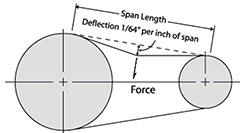
But, once the pulley alignment is done, equally important is to set the belts to the proper tension. Typically, the correct tension is one that allows the belt to be deflected on its tight side by a specified amount of force to an amount of 1/64th inch per inch of span length. The span length is the distance between the nearest points of contact of the belts on their sheaves. If this distance is not known, you can use the center distance between the pulleys; that’ll be close enough.
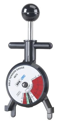
To do this, you use a spring tension gauge, which is a device that measures the amount of force that you apply to something when you push against it or pull on it.
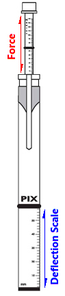
So, say the span length of a given belt drive is 36 inches. You should deflect the belt (in a group of belts, usually the center one, but measure the two outside ones as well) by 36/64″, (or 9/16″) which is 1/64″ of deflection for every inch of span length, and measure how many pounds or newtons of force it takes to do that. This force should not be less (too loose) or more (too tight) than what the manufacturer of the belts recommends for that drive or for that set of belts. Also, you perform this test by pressing down with your gauge upon the belts in the middle of their span length on the “tight side” of the belts. The tight side of the belts is the side that is stretched as the drive turns and the driver pulley applies rotational force to the driven pulley. The return side is the slack side of the belts.
The recommended belt tension deflection forces are usually supplied in a table that takes into account the size, length, and type of belts, the number of belts in the drive, the anticipated application loads and drive ratios of the sheaves. Move the driver until the recommended force specification is met for the desired deflection, being careful not to mess up the sheave alignment while doing so!
Download 5-Step Sheave/Pulley Alignment Procedure
by Alan Luedeking CRL CMRP
Condition Monitoring Expert Tip #10 by Mobius Institute
No, sadly, that is not right. Unless the person has been properly trained, unless the company has specified precision alignment tolerances, and unless the training is followed and the tolerances are achieved, then you are not performing precision alignment.
We see this as a very common problem. Laser alignment systems can achieve terrific results. And a precision-aligned machine is far more reliable than a machine that has been “roughly” aligned with an alignment system, and far superior to a machine aligned with a straight edge. But if your maintenance technicians do not appreciate why that last shim should be installed, and why the motor must be moved such a small amount to the left or right, then those corrections will not be made – and yes, it does matter.
Research by Tedric A. Harris, in the book “Rolling Element Bearing Analysis” (John Wiley & Sons), showed that just 5 minutes (5/60 of a degree) of angular misalignment can reduce the life of a bearing by half. Yes, precision matters!
by Yolanda Lopez
As Published by Maintenance Technology Magazine September 2017 issue
If greater reliability and uptime are of any concern to you, then precision maintenance is a key component in achieving it. This means having clear and simple, yet meaningful, procedures in place for the different tasks involved. Two such tasks are precision alignment and balancing. LUDECA’s 5-Step Procedures will help guide your facility and maintenance staff to achieving precision maintenance.
Get your own copy of these 5-Step Procedures:
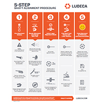
Download 5-Step Shaft Alignment Procedure
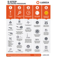
Download 5-Step Balancing Procedure
Why is precision maintenance so important? The reasons are clear:
- Safety
The alignment and balancing procedures lay out the basic steps required to align and balance machines safely, reducing the risk of injury and increasing the likelihood of a quality outcome. Checklists simplify the workflow and serve to remind employees of the processes required to consistently and safely perform the precision maintenance task. - Reliability
Well-aligned and balanced machines run more reliably, with a greatly reduced probability of failure. This allows for better maintenance planning, greatly reduced repair and maintenance expenses, increased uptime, and more profits. - Efficiency
A good alignment procedure ensures that machines are aligned to the proper tolerances for the running condition of the machines, taking into account such things as thermal growth and anticipated positional changes. This ensures that the greatest efficiency is achieved in your running machinery, prolonging their health and reducing power consumption. Studies have shown that well-aligned machines result in a 3% to 10% reduction in power consumption. Noise and heat generation are reduced, producing a safer work environment. - Production Quality
Good alignment and balancing result in better product quality since vibration is minimized, resulting in more uniform and higher product quality. Unexpected breakdowns in production machinery may lead to costly waste from scrappage and high restart costs for the production line. - Training & Procedural Consistency
Once implemented, a procedure ensures all employees involved in the activity face clear and consistent expectations and processes, leading to a better understanding between all staff in the facility. Training expenses can be reduced since often only refresher training is required to update understanding of the technology utilized as updates are rolled out. Records should be kept that document employee training.
The next step in precision maintenance and reliability is the Implementation of formal specifications that detail every step in a task from safety to activity process to documentation, to ensure that anyone involved can follow the procedures and guidelines without confusion, and reach the desired outcome for all machinery types in the plant. Such specifications typically take from two to three months to develop and a further two to three months to roll out and fully implement. LUDECA has written a number of these specifications for customers worldwide. Let us help you as well.
by Alan Luedeking CRL CMRP
LUDECA is proud to announce the new Easy-Laser® XT660 laser shaft alignment system for the United States market. The XT660 is the next evolution in the award-winning Generation XT platform. It builds on the ground-breaking cross-platform technology that was launched last year with the XT440 SHAFT system. You can use your own iOS/Android phone or tablet as a display unit, or purchase the watertight, shockproof rugged XT11 display unit. Or why not do both? The choice is yours! The Easy-Laser® XT Alignment App is free to download, both now and in the future, making it easy to update your tool to the latest features at any time.
The XT660 now offers dot laser measurement technology. You can perform measurements on larger machines and over longer distances. Advanced measurement capabilities, such as continuous sweep and multi-point are now available. The rugged measuring units with integrated Bluetooth® wireless have very long operating times; up to 24 hours!
Easy-Laser® XT660 paves the way for new features with the Generation XT platform. You can export custom PDF alignment reports to a USB flash drive or via Wi-Fi directly to email for documentation of the alignment work. These new features also apply to the XT440 SHAFT alignment system.
LUDECA is also proud to announce the new Easy-Laser® XT190 BTA digital laser tool for belt drive alignment. It can be used “stand-alone” with its built-in display, as an add-on to the XT660 SHAFT system or you can download the free Easy-Laser® XT Alignment App for your phone or tablet. Digital readings allow greater precision and make it easier to meet the alignment tolerances. You can follow the adjustment of the machine in real-time with an interactive 3D view displayed in the App, making it easy to track live horizontal and vertical positional adjustments on the machine.
by Ana Maria Delgado, CRL
Guest post by Bob Dunn at I&E Central, Inc.
I was working with a customer to align sheaves using their Easy-Laser E180 sheave alignment tool. This is a new blower that had been installed by a contractor. Obviously, the contractor did not check alignment before drilling the mounting holes. The horizontal angular error was about 1.25 degrees and required a move of about 1/4″ more than was available given the placement of the bolt holes. Thanks to the digital measurement of the E180, they knew exactly what correction was needed at the feet to align this machine.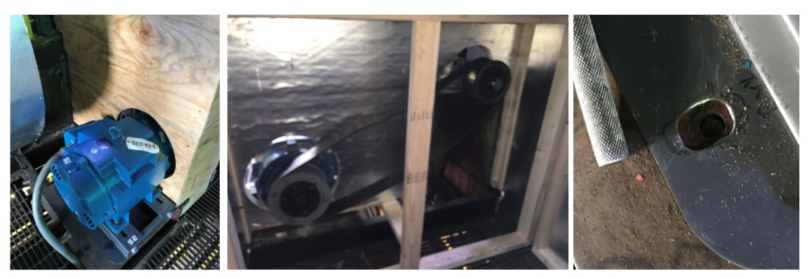
Unfortunately, the solution will be to drill out the holes in the base, then complete the sheave alignment. What should have been a 30-minute job now becomes a much larger project – time and money wasted. My guess is that the contractor checked alignment with a string (or maybe not), which did not get him close enough. Using the right sheave alignment tool makes a difference.
Thanks to Bob Dunn for sharing this case study with us!
by Yolanda Lopez
Guest post by Brandon Weil, CMRP at Eruditio LLC
Belts, chains, and sprockets, chances are you have at least one if not all of these in your facility and chances are you’re relying heavily on experience and judgment instead of quantitative inspection criteria. All too often the importance of proper inspection techniques and defined replacement criteria for these critical parts are overlooked. Don’t believe me? Just pull up some of your PM inspection procedures, discuss the topic at a toolbox meeting, or observe someone performing the inspection, you might be surprised at the range of answers and opinions. If there isn’t a specific measurement or min/max criteria, then you’re leaving the inspection up to chance. Another thing to consider is if these parts aren’t being installed properly in the first place you will undoubtedly see premature failures and reduced operational life. Precision maintenance installation tools such as laser alignment for shafts, pulleys, and chains make a world of difference in preventing the introduction of infant mortality-related failures like premature bearing failures, belt and pulley wear, etc.
The good news is that you can start improving the quality of your preventative maintenance inspections almost immediately; all you need are a few basic low-cost tools [Click Here] and you will find a document with inspection criteria for these three parts to get you started. Improving your PM inspection procedure, putting the right tools in the right hands, and setting quantitative standards for your inspection is a very low-cost high-return activity that can start paying dividends today.
Download Belt & Chain Storage Best Practices
by Ana Maria Delgado, CRL
I have had the opportunity to see, first hand, the improvement in the quality of alignments our Tradesmen have been able to achieve and I attribute it to the availability of the wall charts received from LUDECA as the main reason. There isn’t much that the charts don’t cover but, it’s the references to thermal growth and the causes of lack of repeatability and response to corrections made that are the most helpful at least for us. As the Vibration Analyst onsite it’s been a win-win!!! Thanks from all of us at Cameco – Cigar Lake Operation —Ben Harrison, Reliability Technologist
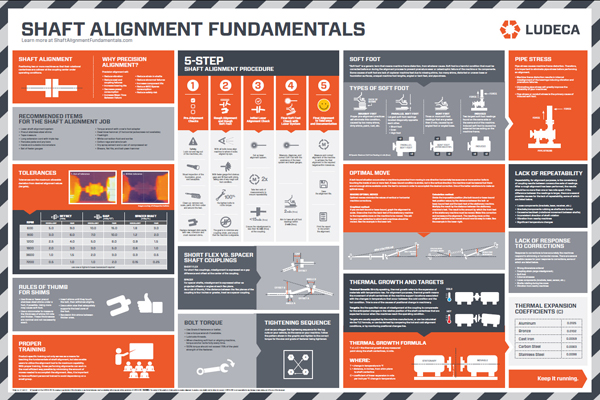
Request your copy of the LUDECA Shaft Alignment Fundamentals wall chart
by Ana Maria Delgado, CRL