Complex Jackshaft alignment made simple with experience and an Easy-Laser XT660 Shaft Alignment Tool

When you are working with nature, you treat it with respect. And that’s what this dam facility on the Kootenay River in British Columbia does (image, above left). When you harness the power of a river you need your control systems to work. The spillway gates control the level of the dam and in this example, it is lifted and lowered by two Worm Drives that are approximately 33 feet apart, so it’s a large gate. Pictured (above right) is one of the worm drives.
The drive motor and gearbox are mounted in the middle and the complete system is being replaced. As with any machinery installation work there will be a lot of alignment work required, including the two drive shafts which are 176 inches in length.
Chad Hansen of CH Mechanical was asked to do the shaft alignment work on the complete drive. Chad owns an EASY LASER XT660 shaft alignment tool which can cover a measurement distance of over 66 feet. He is confident he can do this work however, as the largest span from worm drive to worm drive is 33 feet. But the work doesn’t start on site, it starts back in the shop.
Aligning the Drive Assembly
This is the drive assembly (image below) for the two jackshafts that drive the worm drives, which opens/closes the gate. A new base had been fabricated, which in its self is a nice piece of work! Notice that it has four different levels with machine components attached. That’s 8 mounting foot pads, one for each mounting bolt. Each of these mounting surfaces should be flat. Each set of mounting pads should also be coplanar; for example, the four foot pads for the motor should be flat. I could go on about the importance of base flatness but i’ll leave that for another post!)
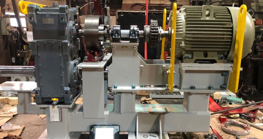
Now let’s look at the machine’s components. A good-sized motor with standard mounting feet has a shaft coupled with a chain coupling. This connects to the short spacer shaft supported by two pillow block bearings. This is coupled with a flange-mounted rigid coupling which then connects to a drum brake that is mounted on the gearbox input shaft. Now for the gearbox. The one output shaft is obvious, coming out of the front side of the gearbox (left side of image) with the shaft parallel to the motor shaft. The other shaft is harder to see, on the opposite side, under the drum brake pedestal running underneath the motor. The motor and pillow block base will be removed during the installation but this pre-assemble is to make sure it all fits without being bolt-bound or base-bound.
The most important aspect of this machine’s installation is mounting the gearbox and setting the brake, and that where Chad starts. The gearbox input shaft must be parallel with the mounting surface of the brake. This can be achieved by shimming the gearbox and/or the brake. It’s usually a combination of both to get the optimum move but its time well spent. The end goal is that there is no gearbox shaft deflection when the brake is applied. This means no angle or offset. Next, the spacer shaft is aligned to the gearbox shaft. This is a rigid coupling, so it is best to do this with the coupling open (separated). This is done by using the two built-in electronic inclinometers in the measuring units and either the 9-12-3 measurement method or EasyTurn measurement method. Either way you get a high accuracy, repeatable alignment.
After this you can align the motor to the spacer shaft. With the Easy-Laser XT660 Shaft Alignment tool Chad has different measurement method options because this alignment work is important. Here, he can use the multipoint measurement method and take a series of measurements. He can align the motor to the spacer shaft then go over the top to align the motor to the gearbox shaft, his choice. He can use the new ANSI standard tolerances which is in the display and will be shown in the report.
Installing the Drive Assembly and Aligning the Jackshafts
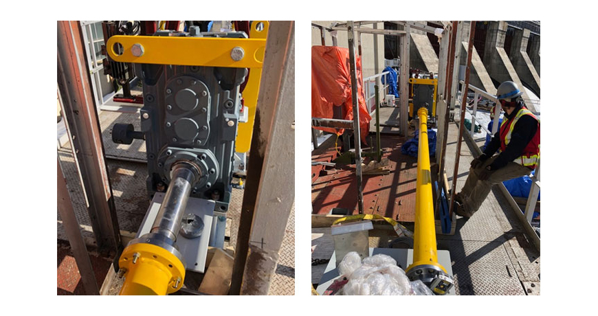
The whole gearbox and drive assembly are installed on site. However, the bearing pedestal, motor, and motor base has been removed for easy access (image, below left).
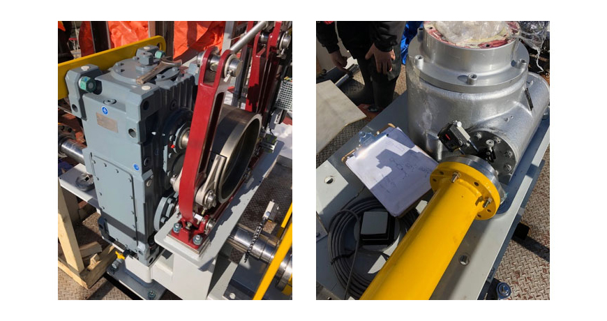 The right-side jackshaft is installed first, that’s the one closest to the dam. You can see the moveable laser/detector unit mounted on the output shaft just below the drum brake. The worm drive (image, above right) will be the stationary machine with the other laser/detector mounted. The laser alignment data is collected using EASY-LASER’s EasyTurn measurement method with the results showing the amount of misalignment and in which direction they need to move the machine.
The alignment work is completed. There is a little wiggle room at the worm drives however, most of the corrections are made by moving the drive assembly. CH Mechanical uses the new ANSI alignment tolerance for spacer/jackshafts. They are well within spec so it’s a job well done. The actual numbers remain the property of the Dam, so we won’t publish them. However, there is a lot of margin on a 176-inch shaft length. That’s not to say that it’s a quick job, its not. Its actually a very complex job made easy by Chad Hansen and his EASY-LASER XT660 shaft alignment tool.
Thank you John Lambert with Benchmark PDM for sharing this successful story with us!
Filed under:
Alignment, Articles and Case Studies by Diana Pereda