Correcting a shaft alignment problem brings a vast set of challenges to the workload of our mechanics, millwright, and engineers. Those issues could be in the form of physical constraints preventing movement or distortion from poor bases or pipe stress. They could be as simple and frustrating as soft foot or old bent shims. But, one of the most intimidating alignments out there is the spacer shaft, especially when it comes to extreme distances.
I am not an engineer—oh-oh, half of my readers just left—but for those of you still reading, I want to provide you with a few tips compiled by a few of us here at LUDECA to make your spacer shaft alignments with lasers easier. So, without wasting too much of your time, I refer you to the 5-Step Shaft Alignment Procedure.
Just kidding… sort of.
There are many different types of spacer shafts. So, what is a spacer shaft?
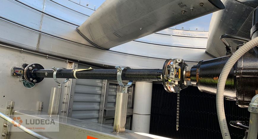
Picture 1
Generally speaking, a spacer shaft (spool, spider, jackshaft, or whatever you want to call it), is a coupling of some kind that spans more than 4″ or 101.6 mm between its flex planes. My goal in this blog is to provide five simple tips to help you align spacers without getting into the mathematical process. I’ll save those questions for the engineers. Keep in mind, these are suggestions for laser alignment of spacer shafts.
Spacer Shaft Tip 1:
Try to make sure you can square the two sensors to one another. By either using the inclinometers, lasers to targets, or really good eyesight – it tells you a lot if your sensors square up to one another. This seems like a simple or obvious tip (which is why it’s the first one) but, this also provides you with an indicator for TIP 2!
Spacer Shaft Tip 2:
There are two primary ways of aligning spacers: the Two-Step Method and the Single-Shot Method. Now that you can determine how bad your misalignment is – you can choose the method that fits best. The single-shot method is typically done when the alignment isn’t grossly out and the sensors would be mounted on the far ends of each spacer component. The two-step method is used when there is a significant amount of angle or offset to correct. The sensors should be mounted across each flex plane of the spacer individually to close the angle at each.
Picture 2
Spacer Shaft Tip 3:
Soft Foot. If you are following our 5-Step procedure you probably understood that I went a little out of order. However, we needed to know which components we were moving first, right? Now that we have a plan we have a procedure. Soft Foot matters, and it should be corrected and fall within the allowable tolerance. Use this time to also correct any challenges that can be identified visually (clean the base, good shims, etc.) You may want to take a look at our Soft Foot Find and Fix Procedure for an outline of types of Soft Foot including causes and corrections.
Spacer Shaft Tip 4:
Know your tolerances. There are 1,001 blogs and articles on spacer tolerances on the web. The best thing you can do is know what your tolerances are for that specific alignment. Yes, spacer tolerances can be more forgiving in terms of the required corrections at distances. However, there are many ways to represent those spacer tolerances. You could have a specification that is Angle/Angle or Offset/Offset or a combination of those. Make sure you are aware of the required values and representation.
Spacer Shaft Tip 5:
Patience. Don’t rush to get it done. Do it right so you don’t have to do it again.
Picture 3 and 4
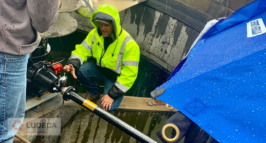
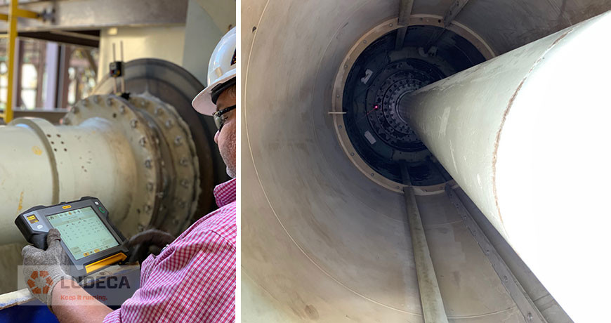
So, when you find yourself facing a spacer shaft, spool piece, or jackshaft, take a deep breath and follow the same rules of alignment that experience has taught us. I would also like to thank Joel Chapman from Entech Sales & Service Inc. for a lesson in cooling tower alignment in the rain (the umbrella was for me, not the laser, it was very nice of him – picture 2). And, thank you Richard Armstrong of TRACE Reliability, a LUDECA, INC. solutions provider who makes our customers a priority. He shared pictures 3 and 4 of an ID Fan in Louisiana that measured 289” inches from sensor to sensor.
Filed under:
Alignment, Maintenance Tips by Matt Hadad CRL