Machines are like people. They all have certain similarities but are different in many ways. Two exact machines in the same operation may perform and respond quite differently.
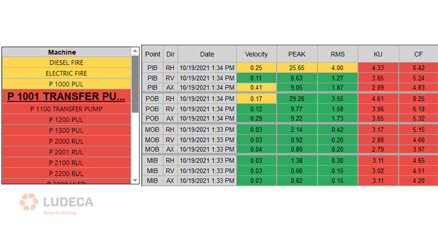
Setting alarm values for your vibration measurements is critical for the success of your vibration monitoring program. Alarms will help the analyst identify when conditions on the machine have changed and assist in identifying specific fault conditions. All of this makes the analysis much more accurate and easier. Additionally, this can reduce the amount of time required to analyze the vibration data collected. However, for all this to work the alarms must be set up correctly.
Does the question become what alarm values do you use? Determination of alarm values is especially difficult for the inexperienced analyst, or when no historical data is available for the equipment. Many sources have published generic alarms based upon specific equipment types and operational speeds. These published alarms can be very valuable in certain circumstances. However, as stated previously, machines are like people and are different in their performance and responses. The best method is to collect data on the equipment for a period of time and set statistical alarms for each machine based on its unique operating characteristics, performance, and type.
This method will always provide the best results for your vibration program and increase the accuracy of your analysis.
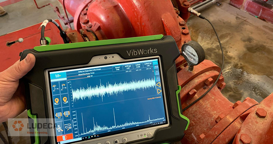
Check out our VIBWORKS vibration analyzer.
by Trent Phillips
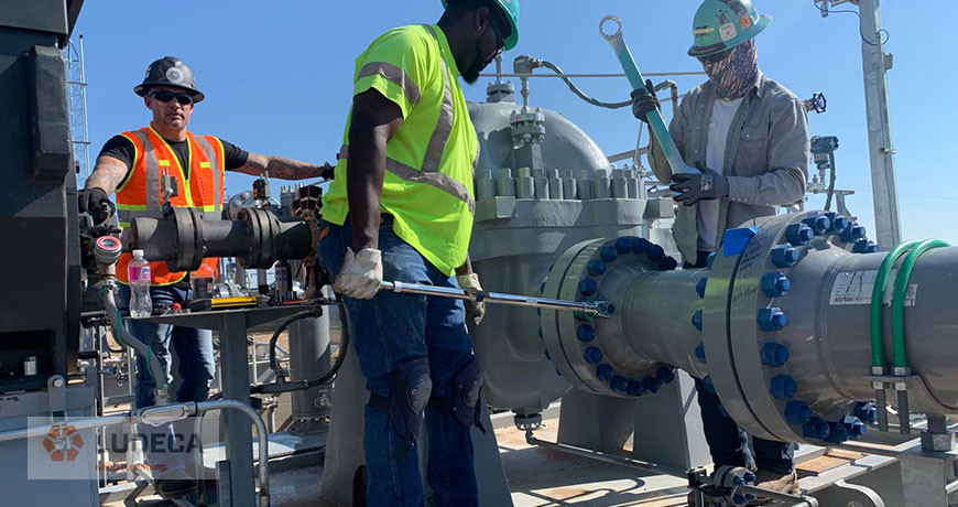
In my previous blog Torque: Why, How, and Where, we talked about the why. Now we need to achieve a correct clamping force, and so we will discuss how to get there.
Here are the normal ways of torquing hardware, in order from the least accurate to the most accurate.
- Impacting
- Hand tightening
- Using a torque wrench
- Torque plus turn
- Hydraulic rotation
- Hydraulic tension
We are going to break down each of these techniques and see what the results can be. Some are good results; others are not so good.
- Impacting – This is very common because it is easy to do and fast. The amount of force derived from an impact, whether it is battery powered or air driven, is almost impossible to know. How fresh is the battery? How much air pressure and volume is supplied by the hose? How loose are the internals of the impact wrench itself? How loose is the socket on the drive? How loose is the socket on the fastener? Is there an extension between the impact and the socket? More about that extension will be discussed later, but you can tell from all of those questions that there are so many variables that accuracy will always be questionable. The next step up on the ladder of accuracy is hand tightening.
- Hand tightening – Some people have it, some don’t. A lot of what is done in the professional world is done with experience. Certain industries have a level of experience that instills some great “Feel” for the tasks. Aircraft Mechanics win this category, hands-down (if you will excuse the pun), because everything they do is critical and sometimes even exotic. Like a titanium bolt going into an aluminum, or even magnesium, receiver. This requires a level of attention and feel that a lot of technicians just do not possess. They have an ingrained muscle memory from years of this type of work and can get very close to specified torque in a lot of cases. I, personally, do not have that kind of feel. Even with that knowledge and tactile experience, they will always verify with a torque wrench because they must! It’s part of the procedures, and no A&P mechanic wishes to be the one who just let an aircraft fall out of the sky. That leads us to the next rung on the ladder.
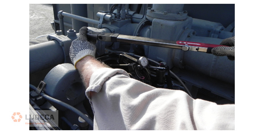
- Torque wrench – Here we are using a calibrated (hopefully) device to accurately measure how much rotational force we are inputting into a fastener. This too has some rules that must be observed to perform the job correctly.
a. No double-click: As in, bouncing off the end of the handle like it’s your own shop Pogo stick. The thought behind the double click is to ensure that the fastener is tight, and boy is it! Since the torque wrench did not return to a relaxed position, it just clicked again, but went way past the desired torque. In a case where something like 100 lb./ft. is desired, that second click made it go to perhaps 170 lb./ft. The proper way to check is to pull slowly and smoothly to the “click”, anticipating when it should happen and stopping at that point. Then, let the tool totally relax and pull again the same way. If the tool clicks with the fastener not turning anymore, then you will know it is torqued correctly.
b. The extension we mentioned earlier: A common misconception is that if you add an extension, you lose torque. While this is true with an impact wrench (because you are adding mechanical looseness), this is not the case with an extension on a torque wrench. We have a load cell that we use to prove this concept, and with about 8 feet of extensions, we asked the technician to apply 100 lb./ft. of torque. There was definitely more flex in the tool, but once all of that flex was taken up, our load cell indicated that he had put 102.3 lb./ft. of force into the sensor. So, there is no significant loss of torque from the use of extensions provided that the tool is used correctly.
c. Torque wrench storage – When I was growing up working in the family shop, my grandfather would lose his cool if he found a torque wrench put away at anything other than Zero. He would declare the tool off limits until it could be calibrated again. Unfortunately, this is another misconception about storage. Every tool manufacturer publishes what setting to set that tool to for storage, and it is normally never zero. The spring in that handle actually wants a set amount of force kept on it so it cannot drift with environmental changes like temperature or vibration. Some are specified to be set at 10% of max, or maybe at the lowest available setting, others have a set number. These specs are normally in the manual that came with the tool, but often that has been discarded or misplaced. But a few minutes on Google will surely provide the answer.
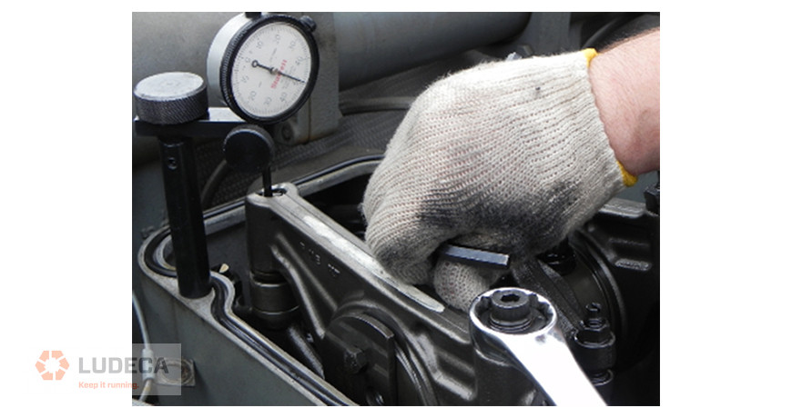
- Torque plus Turn – This picked up a lot of adherents in the 1960’s and 70’s. It is way more accurate than the torque wrench, because in a lot of cases, the torque specified was higher than some torque wrenches could register. The idea is to put a lower torque into the joint using the torque wrench, and then adding the degrees to achieve the much higher clamping force. This works great, especially if the manufacturer supplies a gauge to measure that angle. There is very little guesswork, just turn to the indicated degrees. If you need more than that, we need to get more complex equipment involved, such as hydraulics.
- Hydraulic rotation – This is for the big boys. Anyone who has had to torque something big can attest to how hard that can be with hand tools, even with a torque multiplier. Hydraulic rotation takes that task much easier, albeit more costly. This can take a large fastener, rotate it to 1000 lb./ft. or more with no trouble at all. But by the same token it is more critical to know what that force needs to be. Without much effort, it becomes very easy to over-tighten something, and that could be just as bad as under tightening. If you need more accuracy than that, then you need to apply hydraulics in a different way.
- Hydraulic Tension – this is the most accurate way to tighten a large joint. The engineers that design systems that require this know exactly how much clamping force is needed and specify the amount of force to use. In this case, a collar is threaded onto a stud and the specified pressure is applied to that collar. When it stretches the stud by the correct amount, the nut is simply run down by hand and the pressure is released. This allows the “elastic” properties of that stud to clamp the joint together. The only real issue here is the fatigue that is put into that fastener. Some manufacturers specify how many times a stud can be stretched, while others will have the tech measure the stud each time to insure it has not gone into a yield or plasticized condition.
All of these methods have their place. Anything that makes the job more accurate and more repeatable creates the opportunity for better running conditions. We haven’t yet touched on the topics of torque specs, or lubrication. These will be interesting topics for another day.
Visit our Knowledge Center for resources and tools to help you succeed when implementing and using our maintenance technologies.
Precision Maintenance: The Torque Wrench. Check Out These 15 Helpful Tips!
by Diana Pereda
Vibration Route Frequency
How often do you collect vibration data on your equipment? Is it monthly, quarterly, or even yearly? Most of the time management will allow data collection frequencies based upon the importance they assign to vibration analysis or available resources at the time. Management may ask that vibration data be collected every month or even more frequently if the machine has failed recently. Different companies and managers use different means to determine how often to collect vibration data or any other CM data for that matter.
Assigning arbitrary data collection frequencies (routes) to your equipment may do your reliability efforts a disservice. The best method is to determine the failure intervals of the failure modes (bearing defects, etc.) in the equipment. Assign data collection intervals short enough to identify these failures. For example, a bearing may develop a failure on day one and run for ninety days before it causes the machine to fail. If the machine is monitored with vibration analysis every ninety days, then your analyst may never identify the bearing failure condition in the machine. The result is that your machine will most likely fail without anyone being aware of the issue. If the same machine is monitored monthly with vibration analysis, then the bearing failure condition would most likely be identified with your vibration monitoring program. This would alert the maintenance department of the issue and allow appropriate repair efforts to be budgeted and scheduled.
Watch our Reliability Matters: What Can I Do? video to learn the benefits of vibration monitoring to keep your equipment running efficiently.
by Trent Phillips
I recently spoke to a reliability engineer who was rolling out our alignment and vibration equipment to fifteen plants across the U.S. He involved us early on in the process. His company didn’t just set aside budget money for the equipment purchase, but also enough to properly train their field service personnel in how to properly use and benefit from the new technologies. We addressed not only the use of the alignment tools but also proper equipment installation, lubrication, soft foot, pipe strain, thermal growth, etc.
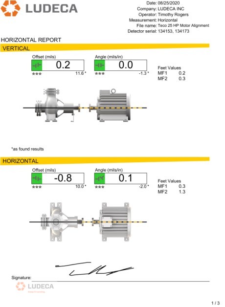
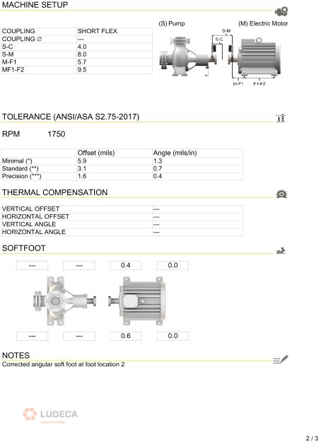
One of the key topics of discussion was alignment tolerances. Since this customer has high-speed ammonia compressors, this was a key concern for good alignment and they, therefore, adopted the new ANSI/ASA Standards alignment tolerances as their corporate standard. Since these tolerances are built into our laser alignment system, it was not only easy for the user to determine if the measured alignment met their established corporate alignment standards, but also for management to review the work to ensure it was correctly completed. This oversight is easily accomplished via signed PDF documentation that allows storage of the “as found” and “as left” alignment results with the work order, and also allows for easy report generation in the field for review.
I was told that their vibration analysis program still identified equipment that was out of the established alignment tolerances. How could this happen? It turned out that contractors were performing work without being held to the same standards as plant personnel, including meeting the prescribed alignment tolerances or using specific alignment equipment to perform the work. In addition, the contractor was not required to provide a copy of the results for review and digital storage.
How could this happen? Unfortunately, it is not so uncommon. Many facilities or corporations do not require that maintenance activities be performed to standards or with the equipment they can trust for the results. Additionally, they do not clearly write job plans that are issued to internal maintenance employees or contractors that specify how the acceptable results are to be achieved (what steps are required, what tools are required, what standards should be met, and what documentation of results is required.) In addition, the Maintenance Planner does not review the results of the completed work to confirm that it was satisfactorily completed within acceptable specifications. Oversight failures, as well as specification failures in job plans and work orders, can easily result in continued reliability and maintenance issues and repeated or wasted efforts to keep your equipment running.
Fortunately, the answer is not too complicated. If the problem is that the contractor is not performing the job to company standards, then the job scope and specification need to be more clearly presented in the bidding process for a job. If the requirements are clearly stated and accepted by the contractor, then they must abide by those standards. Otherwise, the contractor may risk two things: having to come back on-site to fix the issue under warranty and losing you as a customer in the long run. Communication is the key here. Being open and upfront about the expectations can avoid a lot of headaches that will linger long after the contractor has completed the job. In the case of contractors that are “permanently in-house,” the answer is a bit more complicated. A good approach to solving this issue is to involve them in training efforts within the organization. This will get them better prepared for the tasks to be done at the site. If all else fails, have a third-party expert review the work to help understand why the work was not conducted or finished properly.
by Frank Seidenthal CRL
The current business operating culture is experiencing a sea change. Some are being brought on by local and global political shifts, but more is being brought about by a worldwide pandemic and the challenges of having properly trained people available to keep equipment running as expected. Lofty goals have been promulgated in boardrooms, investor meetings, and public relations campaigns, with only marginal guidance given to operations staff to reach those goals. In some cases, these goals are received as “pie in the sky” statements and dismissed in the field as unattainable. In reality, a lot of those goals can be met and exceeded with proper work practices.
Let’s start by stating some of these goals and see what it takes to meet them without requiring a huge overhaul of operations. Upgrading tools and introducing more complete training should be part of any company’s operating plan, so we will see how much impact can be made by implementing solid information and work techniques that can impact the output of the machines, the reduction of stress of maintenance, and the achieved realization of environmental compliance.
Methane Release Reduction
Several operators in the world have a stated goal of a 10% reduction year-over-year for methane releases. These releases come from several sources, whether they are production assets or transmission lines. Very sophisticated equipment has been developed over the years to spot and record leakage, sometimes sampling the air to find the smallest PPM (Parts per Million) of hydrocarbon escaping vessels and piping. That works great when all the “Bad Actors” have been eliminated, but the truth is that most sites have the kind of leaks that overwhelm this type of sensor and make it hard to pinpoint individual sources. Maybe taking a step back and relying on tools that are less sophisticated will have a larger impact. Technology, like the SDT SonaVu, can quickly find leaks and document the source for repair and verification. Some of these leaks are large enough that the first round of audits will yield a rate of reduction much greater than 10%. The only problem for the next audit would be to come up with the same rate of success if everything is already properly repaired!

Emissions Reduction
Current emissions standards are calculated by how much CO (Carbon Monoxide), NOx (Oxides of Nitrogen), and VOC’s (Volatile Organic Compounds) are generated and released in the exhaust stream of an engine, compared to the amount of Horsepower generated by that engine. Any sort of parasitic loss within the system requires that engine work harder to accomplish the work. Reducing that loss allows for more Horsepower to be used for production or provides a buffer for the working envelope of emissions. An engine that is working above rated Horsepower is actually working outside of that envelope because the permits involved are written specifically for the advertised power, nothing over that. So how can we reduce the amount of power needed from an engine to get it back into compliance?
Stay tuned for my next blog in this series where I discuss how to reduce the amount of power needed from an engine to get it back into compliance!
by Diana Pereda
Having taken an inventory of the assets in your plant, you have identified the right tools and training that are needed to minimize unplanned work and avoid creating new defects. Even better, you’ve done some economic analysis, using conservative values, which showed less than a one-year payback and projected substantial recurring annual savings through condition monitoring (CdM) and precision maintenance (PcM).

With the strategy and economic analysis in hand, you’ve convinced your plant manager that CdM and PcM are the keys to driving reliability and profitability. The plant manager funds your equipment and training request. Over the next several months you optimize your interval-based and condition monitoring tasks, train your team members and create CdM routes and train your team on precision maintenance practices.
The CdM and PcM programs start out great. Your team identifies and resolves defects that might have gone unnoticed and perhaps catastrophically failed. The plant manager is happy, your team feels like they’re doing good work. Things are great.
Unfortunately, there is a property of all systems in nature. Systems tend to move from high states of energy to lower states of energy over time. Your CdM and PcM ‘systems’ are no different. As the energy dissipates, the only way to restore the system is to put energy into it.
Leaders have a central role in adding energy to keep systems functioning at a high level. There are three things leaders must do:
- Create a culture that will sustain the performance.
- Provide what’s needed for the team to continue to perform.
- Keep the focus on the big picture – safely delivering asset reliability that generates the best business performance.
Culture is what most people do most of the time. What people do are behaviors. Behaviors are based on long-term memories. Long-term memories are formed as short-term learning is consolidated through repetition. Training loads information into short-term memory. Practice converts short-term to long-term memories. Additional practice generates habits. When enough people have the same habits, those habits become the culture.
Leaders play a role in developing a culture in two ways. First, by providing direction, guidance, and resources. Direction includes mission, vision, values, and objectives. The guidance includes policies, plans, processes, procedures, and measures. Resources include funding, training, equipment purchases/replacements, and time for people to achieve and maintain habits.
Second, leaders develop and reinforce culture by applying productive leadership. Leaders should want to be leaders and want to be accountable. They need to learn and apply leadership roles, leadership attributes, and leadership skills. They should understand and properly apply sources of position and personal power. Leaders must also understand how to influence others based on needs and motivations. And leaders should set motivating goals. More information on these leadership elements can be found in my book, The Productive Leadership System.

Providing what’s needed for the team to perform means making sure your team has what they need to continue carrying out your direction and guidance. Turnover happens. People retire, get promoted, move to other positions, etc. Make sure there is good support in place to train new people and upgrade the skills of current technicians. Leaders have a role in this by planning, budgeting, and defending expenditures for training, replacing/upgrading tools, calibrating sensors, and upgrading software and firmware.
Leaders have a role in keeping the focus on the big picture by identifying and communicating matters related to the CdM and PcM programs. There can be counter-productive matters like operations not allowing time for rotating equipment to be precision aligned or balanced, or not heeding a warning that a bearing is about to fail. Communicate when positive things have occurred; a 50% increase in critical motor mean time between failure, 15% reduction in unplanned work orders, and 5% reduced maintenance costs as a percentage of the total cost.
Thank you Tom Moriarty with Alidade MER, Inc. for sharing this excellent and informative piece with us!
by Diana Pereda
In recent years, “Defect Elimination” has become a hot topic in the reliability world. But what exactly does defect elimination mean? How does it differ from other maintenance practices? Is it more than just a new way to describe planned and predictive maintenance?

Let me start by answering a more basic question. What is a defect? According to Merriam Webster’s online dictionary, a defect is defined as “an imperfection that impairs worth or utility”. The simple definition of a defect that we have used for the past 25 years in The Manufacturing Game® workshops is “Anything that erodes value, reduces production, compromises health, safety or environmental performance or creates waste”. Or in the words of the fictional Chance Brooks, plant manager turned corporate manager in the book Don’t Just Fix It, Improve It “…I came to regard defects as my real enemy. I always thought of them as the little imperfections that caused all of our problems and upsets. Some were big and some small, but when they lined up in just the right way… kaboom!!! A catastrophe would hit.”
A lot of time and attention has been paid to breaking the reactive maintenance cycle – equipment fails, operations call maintenance, maintenance repairs the equipment and turns it back over to operations – rinse and repeat.
Many organizations now perform time-based preventive maintenance, use predictive technologies, and perform operator rounds, all to find defects when they are. Then effective planning (the what, why, and how of the job) and scheduling (the when and by whom of the job) are employed to remove those defects prior to the functional failure or perish the thought, catastrophic failure of the equipment. Those are all characteristics of planned maintenance – simply put, finding defects and efficiently removing them before they cause a failure. A much more efficient and cost-effective approach than fixing broken stuff!
But what can be done to prevent defects from getting into the equipment in the first place? Like death and taxes, having some defects is a certainty – normal wear and tear happens. But most organizations have far more defects than can be ascribed to normal wear and tear. There’s no doubt that “extra” defects sneak in based on how we operate and maintain the equipment. It’s these defects that are not inevitable. And if we prevent them from ever getting into the equipment, we can avoid all of that work required to detect and remove them.
Misalignment is one of those “extra” defects that can be avoided through proper repair and installation techniques, both of which are made significantly easier and more effective with the use of laser alignment tools. Properly aligned equipment has less machine vibration, fewer bearing and coupling failures, and may even consume less energy.

But the opportunities don’t stop there. Tools that have historically been used in support of planned maintenance to find defects that are hidden from the human senses can also be used in a defect elimination capacity to avoid putting defects into the equipment in the first place. For example, ultrasound solutions can be used to provide insight into the current health of an asset in a planned maintenance capacity, but they can also be used in a defect elimination capacity to ensure that the proper amount of lubrication is administered, avoiding the introduction of over or under lubrication defects.

To achieve truly breakthrough performance, an organization has to do more than improve their work efficiency through Planned Maintenance. They must find ways to make some of the work go away. That is where harnessing the power of site‑wide Defect Elimination and available technologies can provide true leverage. To achieve sustainable reliability improvements, the frontline workforce can make or break you. So don’t just tell them about it, don’t just show them; instead, give everyone in the organization a role to play in the process so that they can truly understand and contribute. That brings true buy-in and with it a fighting chance at sustainability. Go beyond Planned Maintenance. Don’t Just Fix It, Improve It!
Thank you Michelle Ledet Henley with The Manufacturing Game for sharing this informative article on defect elimination with us!
by Diana Pereda
The following tips are ideas to consider for when “the going gets tough”, meaning that problems like residual soft foot, “bad geometry”, or becoming bolt-bound impede your ability to easily obtain an excellent alignment. But first, a few definitions:
- Residual soft foot: More soft foot than you are comfortable with, but can’t do anything about. Can be caused by problems like slightly angled feet or a bit of pipe strain.
- Bad geometry: Equipment where the distance from the coupling center to the front feet is equal to or greater than the distance from the front feet to the back feet.
- Becoming bolt-bound or base-bound: When alignment corrections can’t be made because you have run out of room in the anchor bolt holes in the feet, or have to come down but have no shims left under the feet to remove.
Final Vertical Misalignment Correction (Horizontal Misalignment already close)
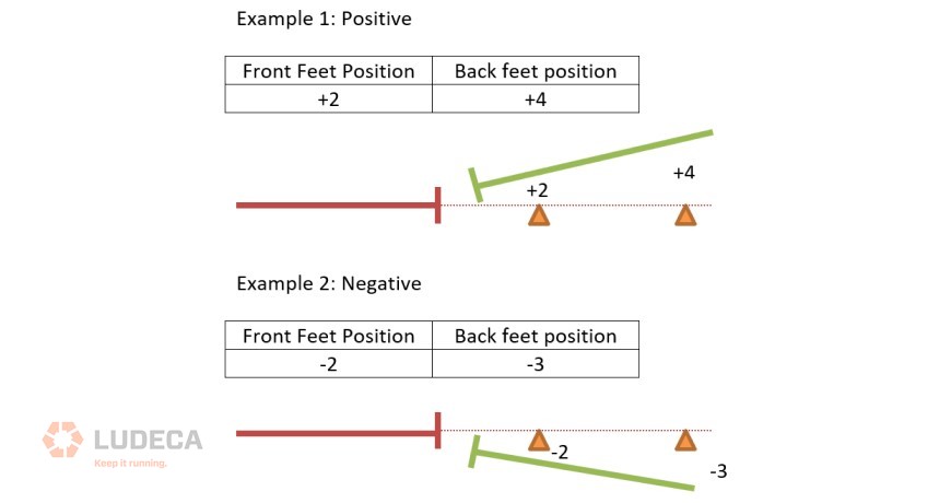
1. Position front feet close to offset tolerance. Finish the alignment by moving the rear feet only.
2. Final foot positioning should make offset at the coupling center decrease. To achieve this, position feet as shown in the below example:
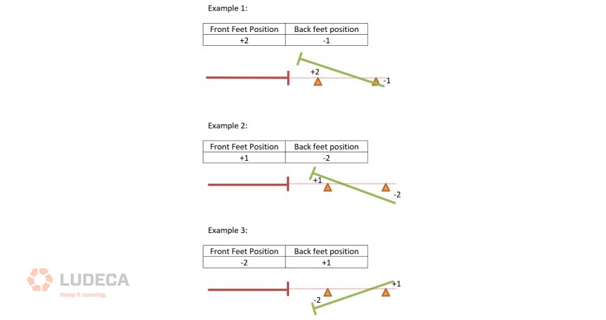
3. One must avoid leaving feet positioned with opposite signs, even if the values are very small. Below is an example:
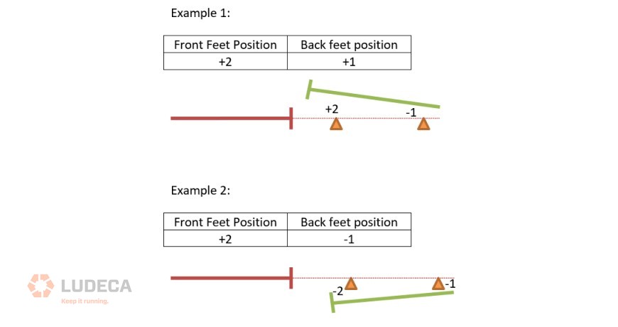
4. One must also avoid allowing the position value of the front feet to be higher than the back feet value, even if they have the same sign. Shown below.
Notes:
- The above rules apply to horizontal corrections as well.
- Remember to torque the anchor bolts on small equipment in steps.
Watch our Shaft Alignment Know-How: What’s Misalignment video to learn the causes and effects of having misalignment in your rotating equipment.
by Diana Pereda
I’m a potential failure! I am the result of improper equipment design, procurement, installation, maintenance, and operation. I exist under extreme conditions for which I was never designed. I haven’t hidden or been silent, but most have ignored me and all have allowed me to grow. I’ll become a risk of severe damage and injury.
One day I will reach my full potential and show everyone what a failure I have become. At that moment, everyone will wish I had been given the early attention and mitigation I deserved.
Don’t feel sorry for me, because I am not alone, and will most likely return. I have created many other potential failures like myself. Some of those failures will cause even more harm and damage. Most likely, I will be reborn on the same equipment again and again due to improper maintenance practices.
If this does not concern you, then do nothing and let me show you what an equipment failure can really cost you when you least expect it and didn’t prepare for it. If you don’t like having me around, then what can you do? Here are some activities your maintenance and engineering departments can perform to prevent me from happening and ensure your equipment is operational upon demand, meaning reliable:
- Design for reliability
- Design for maintainability
- Design for operability
- Manage maintenance backlog
- Plan work, then schedule it and finally ensure it is properly executed
- Focus on PdM activities like vibration monitoring, IR thermography, lubrication analysis, and many more as a routine exercise
- Ensure precision maintenance is routinely done
- Perform operator checks
- Maintain properly written and continually optimized preventative maintenance activities that return value
- Provide training for operators, mechanics, and engineers to help ensure precision maintenance, proper operation, and reliable design
- Perform root cause analysis
- Ensure failure modes and effects analysis is a routine part of your maintenance and reliability efforts
- Ensure that you have identified all critical assets
- Ensure you have mitigation plans in place to deal with critical equipment failures
- Ensure that critical spare parts are available, properly stored, and easily accessible when needed
Visit our Knowledge Center for resources and tools to help you succeed when implementing and using our maintenance technologies! Watch our video tutorials, download infographics, plus explore other helpful information to reduce equipment failures and downtime.
by Diana Pereda
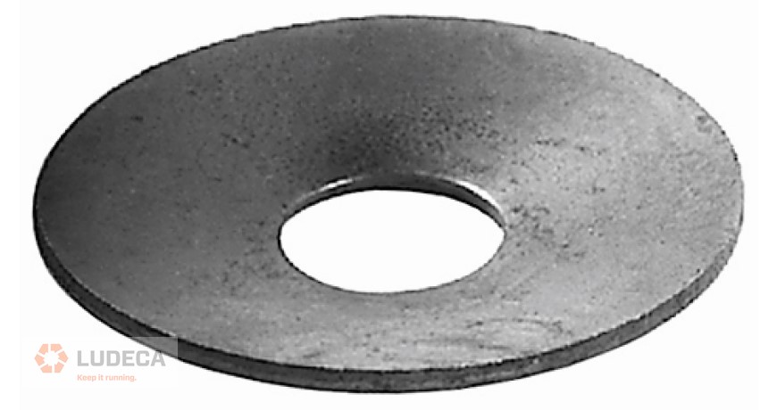
Do your washers resemble cones?
If so, you could be falling victim to a common headache experienced in some shaft alignment jobs. What could mistakenly be diagnosed as soft foot or coupling strain, “dished” or “cupped” washers center themselves in the feet causing the machine you are aligning to move laterally as you tighten the hold-down bolts. Prevent this from happening by performing pre-alignment checks and replacing any washers that exhibit this defect. Also, check the surface of the machine feet for similar grooves that have been cut by washers in the past. These grooves can also cause this effect and make your alignments challenging.
Related Blog: The Impact of Washers on Shaft Alignment
by Diana Pereda
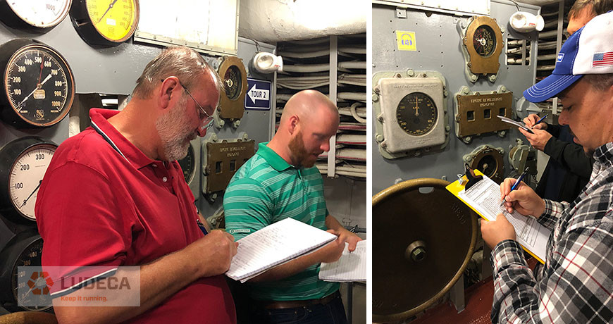
As stated by Daniel Keys Moran, “You can have data without information, but you cannot have information without data.” The driving factor for any reliability program is data; but how do you gather and record the right data to achieve your maintenance and reliability goals? By documenting and generating clear reports with the necessary data. This will permit statistical trends to be developed that can improve uptime and productivity as well as justify repair or replace decisions.
First, let us look at what information should be gathered and documented, followed by how and where you should store the data so that you can use this data over time to develop trends and Key Performance Indicators (KPI’s) to drive your reliability program forward. Harness the data coming out of your maintenance operations and turn it into actionable information that will make a difference in the way you work and what you accomplish.
What data should be captured?
The following list describes the equipment and information that is necessary to make informed decisions and drive the improvement process forward in a maintenance program:
- Instruments used for measurement
- Person(s) completing the task(s)
- Description of the asset
- Date and time
- Tolerance requirements
- As-Found and As-Left measurements
- Reference to the standard used
- Appropriate signatures
Where should my data be stored?
Now that we’ve assembled the needed information, we need to store this data in a way that we can easily access it and refer back to it to identify problems and develop solutions. The preferred storage location should be within your company’s CMMS (Computerized Maintenance Management System.) If your CMMS is configured properly, you may be able to store the As-Found and As-Left measurements directly in the work orders to trend them, thereby allowing the CMMS to automatically create work orders when an asset is out of tolerance. The next alternative is to link the report to a work order and/or asset, allowing the information to be easily accessed within your company. If you don’t have a CMMS, another option is to create a folder structure on a shared drive where the reports can be saved. Keep in mind that there should be a consistent naming structure that is followed by everyone with access to the shared drive so the reports can be ordered correctly and easily located. This will require some training.
What are the Key Benefits?
The goal of any maintenance organization should be asset management with the equipment operated and maintained in a cost-effective manner. Creating detailed reports starting from when the equipment is first installed and continuing throughout the life of the asset allows you to predict when failures may occur so that you can effectively plan and correct the issue in the most efficient manner, in advance of an unplanned failure. With the right data gathered and properly stored, organizations can analyze and develop maintenance strategies to ultimately increase equipment availability, decrease production downtime and generate greater profits for the company. These detailed reports allow communication between operations and maintenance and drive continual improvement throughout the organization by identifying, mitigating, or preventing losses. Ludeca provides a wide range of reliability technologies that generate detailed reports that can be easily shared within an organization to help you “Keep it Running.”
Visit our Knowledge Center for resources and tools to help you succeed when implementing and using our maintenance technologies! Watch our video tutorials, download infographics, plus explore other helpful information to reduce equipment failures and downtime.
by Diana Pereda
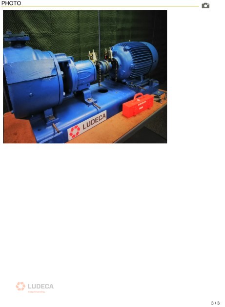
Belt-driven rotating equipment is commonly found in all types of facilities. Typical applications include rolls, fans, motors, shafts, and blowers. It is important to maintain that equipment in order to increase its reliability. Maintenance is essential in today’s industrial environment to ensure assets and equipment are running as reliably as they should.
Like any part that can wear over time, belt-driven equipment should be periodically inspected. This includes the inspection of the pulleys, sheaves, and belts. Worn belts and sheaves should be replaced. Belts should be properly tensioned and the equipment aligned.
It is important to have quantitative values so that the condition of the machine can be evaluated and monitored over time. One way this can be accomplished is through ultrasound and vibration readings. Another value that can be quantified is alignment and belt tension. Belt tension is commonly quantified by force and deflection and determined during the installation of a new belt.
Pulleys and sheaves be should be properly aligned. However, the most common methods rely on pass/fail methods. This includes straight edge and visual laser guides. While they are better than not performing an alignment check, how does one quantify the degree to which the alignment is accomplished? In the same way that it is important to quantify shaft alignment, belt alignment should be quantified as well. This supplies numerical information which the reliability engineer can trend and decide the condition of, in order to plan, rather than react to a maintenance operation.
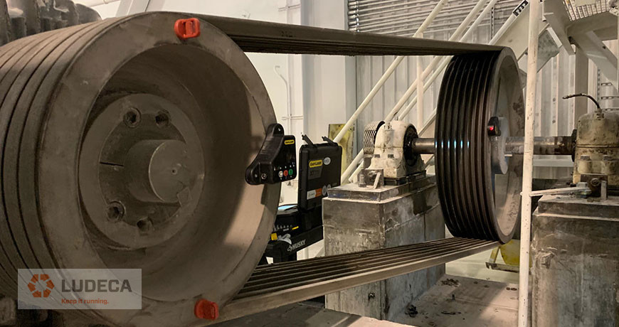
Our Easy-Laser XT190 belt alignment tool can carry out this task and supply numerical values for the current belt alignment condition. A laser transmitter and receiver are placed on the sheaves and pulleys to be aligned. The results are instantaneously projected through the iOS and Android app to supply the current alignment condition in real-time as well as the required corrections. An added benefit is that the users typically only need to access each pulley without having to pull the entire coupling guard off (provided proper lock-out and tag-out procedures are followed). With this advantage, one does not need to visually figure out the alignment as it is all displayed in the app.
The result is that alignments take less time and the reliability engineer can have quantitative data to decide the current and trending alignment condition. This one tool can help move belt-driven rotating equipment from the reactive maintenance stage to the planned and eventually to the precision domain.
Download our Pulley Alignment Guide Plus 5-Step Procedure for information on the implementation of good pulley alignment of belt-driven equipment including terminology, alignment methods, belt maintenance, storage, and tensioning as well as a 5-Step Sheave/Pulley Alignment Procedure.
by Diana Pereda
A few things that should always be inspected during belt PM’s are:
- Inspect grooves for V-belts for wear using a sheave gauge following supplier recommendations.
- Rusted or pitted sheaves should be replaced. Otherwise, belt damage/wear and premature failure can easily result.
- Shiny grooves should not be overlooked and can indicate heavy wear.
- Corrosion on the sheave and especially in the grooves will build up and rapidly wear the belt and result in premature failure. Sheaves should be replaced if corrosion is found.
- Bent sides can introduce wear and damage.
- Replace all belts and never a single belt. Mixing old and new belts results in the load not being shared evenly and could easily lead to damage, premature belt failure and sheave wear.
- The same manufacturer should always be used. In other words, do not mix and match belts from different manufacturers on the same drive.
- Noisy belts can be identified using a squirt bottle with soapy water. Spray the belt during operation with the soapy water. If the noise level changes, then the belt is part of the problem. It should be inspected for damage, proper tension, etc. If the noise remains, then most likely the belt is not part of the problem.
- Ensure that the sheaves are properly aligned. Misalignment will result in premature wear and damage.
Download our Belt & Chain Storage Best Practices which has some basics things to prevent belt and chain damage and contamination thus maximize parts life and performance.
by Diana Pereda
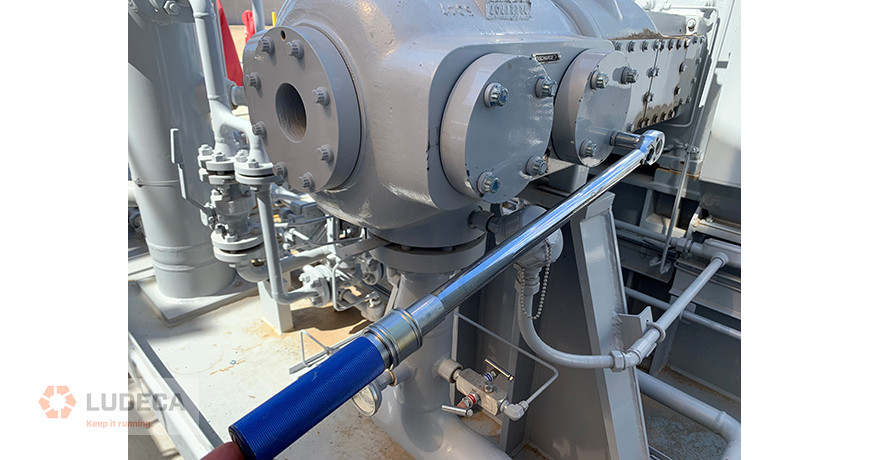
The automotive industry has had a bout with torque related issues recently. This has included over and under torqued items that have lead to failures and even deaths. We see torque related issues constantly in manufacturing facility root cause analysis. Bearing with reduced clearances, life due to over tightening of the housings, loose components due to improper bolt type, and complete disregard for torque specifications are just a couple of recent examples. Part of the solution is proper use of a torque wrench. A torque wrench is a precision instrument designed to apply a specific amount of force to a fastener. Whether tightening head bolts on a small block V-8 engine, lugs for tire and wheel installation, or inspecting fastener tolerances on high-performance equipment, it is extremely important that proper care is used. Guidelines are typically provided noting acceptable torque ranges, the order in which specific fasteners are tightened, and the number of times a fastener must be tightened and loosened to ensure uniform torque application. You must also be mindful of the presence of thread lubricants and the age of the bolt or fastener being used as these affect the torque required. Failure to properly torque fasteners can lead to equipment damage, personal injury, or worse. To help you prevent torque problems in your facility I have collected a few tips for your use. For visual learners, watch How To Use a Torque Wrench.
It is important to follow acceptable safety, maintenance, and use practices, such as:
- Always follow the manufacturer’s directions regarding torque direction, proper force, torque pattern/sequence, use or non-use of lubrication on fasteners, and torque “tighten/release” cycles.
- Do not exceed the recommended working range of the torque wrench. Reliable measurements are based on a percentage of the working range. In general, most mechanical wrenches have a useable range from 20% to 100% of full scale. Most electronic wrenches have a useable range from 10% to 100% of full scale.
- Do not use handle extensions or torque multipliers/cheater bars as we called them unless specifically allowed by the torque wrench manufacturer.
- If you have a torque wrench calibration/verification stand, test the wrench prior to each use.
- Always inspect the tool and check for worn or cracked sockets. Properly lubricate and replace worn parts.
- Avoid dropping or sliding a torque wrench. Dropping a torque wrench on a hard surface can cause the instrument to lose reliable calibration. If you suspect that a wrench has been dropped, have the tool inspected by the manufacturer or reputable calibration service.
- Always store a torque wrench in a protective case and/or location when not in use.
- Avoid exposure to temperature extremes, high humidity, fluid immersion, and corrosive environments. That means do not put them in the parts washer.
- If using a click-type torque wrench, always store it at the lowest level on the scale.
- Avoid marking, etching, or placing labels on torque wrenches.
- Use a torque wrench to apply a specific torque value during the final assembly process. Do not use a torque wrench as the primary means of tightening or loosening fasteners.
- As most torque wrenches are length specific, always grasp the torque wrench in the center of the handle. If two hands need to be used, place one hand on top of the other.
- Apply torque in a slow, methodical manner, and avoid sudden, “jerking” movements.
- When the wrench signals (by clicking, beeping or lights) that a specific torque has been reached, stop pulling immediately.
- After 5,000 cycles or up to one year of use, whichever comes first, have your torque wrench inspected and re-calibrated by the manufacturer or reputable calibration service.
Precision maintenance is key to eliminating your infant mortality and reoccurring failures. A systematic torque application program can get you on your way.
Thank you Shon Isenhour with Eruditio LLC for sharing these useful tips with us!
by Diana Pereda
Below is a short list of when someone should consider using permanently mounted vibration sensors. This scenario would involve either epoxying on the vibration sensors or drilling into the equipment to allow for the sensor to be physically attached to the equipment. A vibration cable is then attached to the sensor and terminated into a junction or switch box. The junction or switch box can vary on the number of points that need to be collected. Once the cables are terminated into the junction box the analyst can collect data directly from the junction box.
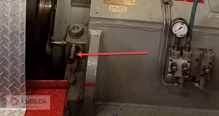

Please note a handheld vibration collector like our VIBWORKS portable vibration data collector, would need to be connected to the junction box to collect vibration data from the permanently mounted sensors.
- Safety – Some equipment can be dangerous to be near
- Saves time – Some equipment can be mounted in hard to reach places
- Avoid hazardous environment – The junction box can be mounted outside the hazardous area
- The first phase of an online deployment – The installation, sensors, and cables are a large cost in any online project. A Cortex online system can be added later to replace the junction box.
Below is a short list of when someone might not consider using permanently mounted vibration sensors. This scenario would involve either epoxying on the vibration sensors or drilling into the equipment to allow for the sensor to be physically attached to the equipment. A vibration cable is then attached to the sensor and terminated into a junction or switch box. The junction or switch box can vary on the number of points that need to be collected. Once the cables are terminated into the junction box the analyst can collect data directly from the junction box.
Please note a handheld vibration collector like our VIBWORKS portable vibration data collector, would need to be connected to the junction box to collect vibration data from the permanently mounted sensors.
- Cost – Multiple sensors and cables can become expensive
- Time – Installation of the sensors, cables, junction boxes, and conduit
- Loss of human interaction – The analyst cannot use their senses (sight, hearing, and touch) as they are not near the machines
- Damaged cables or sensors – Sensors dislocated and cables cut
Do you have any pros or additional cons to using permanently mounted sensors? Do you have any images of junction boxes that are currently in use or comments on why permanently mounted vibration sensors would not function for your applications? Please share those with us!
by Diana Pereda

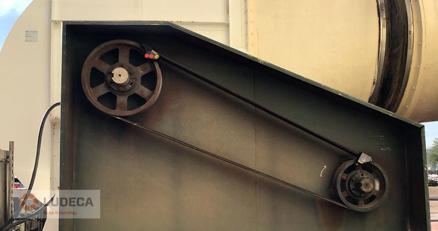
Maintenance departments periodically schedule maintenance checks on their belt- or chain-driven equipment in order to confirm that a good alignment exists between the pulleys or sprockets, especially if evidence of premature wear on the belts, chains, or sprocket teeth is detected.
Visual Pulley Alignment
D90, DotLine Laser, SheaveMaster, or SheaveMaster GreenLine laser pulley alignment tool is ideal. It indicates misalignment in all three degrees of freedom (axial offset, horizontal angularity, and twist angle) instantly.
Digital Pulley Alignment
If you need accountability and documentation of the alignment, then the Easy-Laser XT190 will be the tool you need. The XT190 can be connected to your phone/tablet via the Easy-Laser XT Alignment App or can also be added to your existing Easy-Laser® XT440, XT660, and XT770 shaft alignment systems. Both interfaces will provide a visual representation of the misalignment, the capability of entering tolerances, and a PDF report for documentation purposes.
3 Quick Tips for Precision Alignment
- Always mount your laser pulley alignment tool on the smaller pulley and the targets on the larger one, for maximum resolution.
- Ensure that the mounting surfaces (pulley faces) are free of dirt or rust.
- Don’t forget to verify the proper tension of the belts (or chains) after the alignment.
Download our Pulley Alignment Guide Plus 5-Step Procedure. This guide provides information for the implementation of good pulley alignment of belt-driven equipment including terminology, alignment methods, belt maintenance, storage, and tensioning as well as a 5-Step Sheave/Pulley Alignment Procedure.
by Diana Pereda

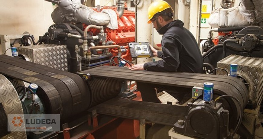
The many applications of Ultrasound, as diverse as they are, rarely get used to their fullest capacity. The Mining Industry poses many challenges in condition monitoring due to various machine types, speeds, and access.
Below are 10 of some of the prime applications for Ultrasound:
- Air Compressors and Blowers designed to supply air on demand often run inefficiently due to leaks. Use Ultrasound and SDT Leak Reporter to locate, document, and report leaks. Download our Leak Management: Find-and-Fix Leak Procedure for an effective procedure to survey your systems and detect leaks.
- Fugitive dust is an environmental problem and is often contained in the mining industry with the use of Baghouse Dust Collectors. The dust collectors require compressed air and diaphragms to purge the baghouse “socks.” A common failure mode for these socks is the ingress of moisture. One source of moisture ingress in compressed air lines are leaks. Another area to utilize ultrasound is for the diaphragms themselves. Use ultrasound to sweep across the diaphragm header to pinpoint a ruptured diaphragm. Typically these are only found after the differential psi indicates plugged bags and requires a physical inspection. Be proactive and efficient with ultrasound.
- Combustion Chambers in dryers that utilize natural gas are another area that can be prone to leaks. Check all the valves, and flanged connections periodically to identify a potential leak.
- Dryers and Kilns run at very slow speeds. Slow speed condition monitoring can be quite difficult using Vibration techniques. The slower the speed, the longer the sampling time and lower the amplitudes. Ultrasound can be utilized to quickly assess the bearing health and to ensure proper lubrication. Although the speed can be quite low, the frequencies of sound generated in rolling element bearings are ultrasonic due to friction of an inadequate lubrication film, or from the presence of subsurface asperities in the early bearing failure stages.
- High Voltage Electricity with potential for arc flash is used both above and below ground. Ultrasound can be used to safely locate arcing, tracking, and corona, without the need to open any panels. Use ultrasound underground on the 4160 V terminal connections, or on your miner Nips to ensure a good tight fit free of discharge. Scan the overhead electrical cables while driving down the conveyor lines and listen for electrical discharge.
- Mines are loaded with long Belt Conveyors both on the surface and underground. Ultrasound is great for monitoring the head pulleys, tail pulleys, take-up pulleys, and for noisy trough idler rollers and return rollers. We all know the havoc a seized idler can wreak on the belt and belt splices.
- The use of grid couplings is quite common on Fans and Crushers. Grid couplings require periodic lubrication and inspection for wear. This requires shutting down the equipment, performing lock out tag out, and disassembly. Use ultrasound and a flex wand to listen under and around the guard of a dryer for a loose fit coupling.
- Hydraulic Systems are used in many applications such as compactors, crushers, and booms on continuous miners. Use the contact RS2 probe to look for faulty psi relief valve and check valves.
- Mines typically have many designated Oxygen-Acetylene Bottle Storage areas. Acetylene is very unstable and can be quite explosive at atmospheric pressures. Use ultrasound to check for leaks and help lower the risk of an explosion.
- Hoists are used to bring ore up from underground. The bearings of the crown sheaves and drums can be quite difficult if not impossible to monitor with vibration analysis as the RPM of the equipment rarely stays constant long enough for good reading. With ultrasound, we need only about 15-20 revolutions for quality reading.
Today’s blog is inspired by a LinkedIn post written by our partners at SDT Ultrasound Solutions.
by Diana Pereda
Maintenance planning, scheduling, and work execution are all critical for the success of best practice returns in maintenance and reliability. Unfortunately, it is easy to confuse and merge these processes together, thereby lowering the efficiency of maintenance activities and the overall health of manufacturing assets. The reality is that each of these efforts is dependent on each other, but separate and critical functions in a well-organized maintenance process.

“We should always plan first, schedule those planned activities and finally ensure the work is properly executed on-time with precision”
The following are stages in creating a well-organized successful maintenance program:
- The first stage in the process is creating a “Work Order Request”. The requestor should always clearly specify “where”, “what”, “why” and “severity” of the work required and enter the work request as early as possible. Work order requests should always be reviewed, prioritized, and approved by management from both operations and maintenance. Doing this requires a valid criticality ranking of the equipment, consisting of specific maintenance, operational, and EHS considerations. This creates buy-in from everyone affected and ensures only necessary work approval and progression through the process.
- Once the work request is approved and prioritized, it becomes a “work order” entering the planning backlog and becomes the responsibility of the Maintenance Planner. The Maintenance Planner is a strategic role and should not be involved in daily maintenance work activities. The maintenance planning stage ensures accurate job/work instructions are created, labor skills and hours required are understood, parts availability is ensured or ordered (some parts may have a long lead-time), required support is identified (contract labor support, cranes, etc.) and safety permits identified. The planner should review existing work plans to see if one is already available for this task or create a new job plan if needed. The Maintenance Planner works with the MRO department and is notified when all required repair parts are available. These parts should be kitted, in a controlled area, so everyone knows they are available to complete the work when the time comes. Once the planner has assured these things are complete the work order and process moves to the next stage.
- Now the work can progress to the “schedule ready” phase and the Maintenance Scheduler takes over. At this stage, everything is in place to get the work done. Functional repair steps are correctly written, safety concerns are identified, and permits issued as needed, parts staged, and available to do the work and common and special tools available. The Maintenance Scheduler works with the maintenance and operations management, and coordinates within workforce restraints (vacations, etc.) and places the work on a schedule to be completed. This schedule is reviewed and approved by all stakeholders and posted so everyone is aware of what they will be working on in the days ahead. At this point, every effort is taken not to break the work schedule and ensure it is completed as planned.
- The Maintenance Supervisor now takes over and assigns individuals to complete the work on the scheduled day/week. The Maintenance Supervisor is responsible for ensuring the daily workflow is followed, problems addressed, the work is correctly completed on-time as scheduled. This individual is working daily in the plant with the maintenance and operational groups.
- The maintenance workers should follow the work instructions and provide feedback with missing steps, parts, tools, safety concerns, and issues and actual time to complete the work assigned to them. This feedback is critical because it allows future work to be better planned, scheduled, and executed, thereby increasing efficiency, reducing unscheduled downtime, and saving cost.
- The Reliability Engineer should use all of this information to analyze and determine routine equipment failure patterns and potential ways to eliminate this work from being required in the future through “Reliability Improvement Projects” (RIE), etc.
Within your facility, you may encounter different job titles as described in this article. However, it is extremely important that the overall roles and processes be in place and routinely followed. Not doing so will lead to dysfunctional work processes and prevent your company from achieving best practice maintenance and reliability goals.
For further reading, we refer your attention to Alan Luedeking’s excellent blog: Reliability – A Holistic Effort.
Need a platform that is going to take your planners/schedulers to the next level? Contact our colleagues at Eruditio.
by Diana Pereda
Correcting a shaft alignment problem brings a vast set of challenges to the workload of our mechanics, millwright, and engineers. Those issues could be in the form of physical constraints preventing movement or distortion from poor bases or pipe stress. They could be as simple and frustrating as soft foot or old bent shims. But, one of the most intimidating alignments out there is the spacer shaft, especially when it comes to extreme distances.
I am not an engineer—oh-oh, half of my readers just left—but for those of you still reading, I want to provide you with a few tips compiled by a few of us here at LUDECA to make your spacer shaft alignments with lasers easier. So, without wasting too much of your time, I refer you to the 5-Step Shaft Alignment Procedure.
Just kidding… sort of.
There are many different types of spacer shafts. So, what is a spacer shaft?
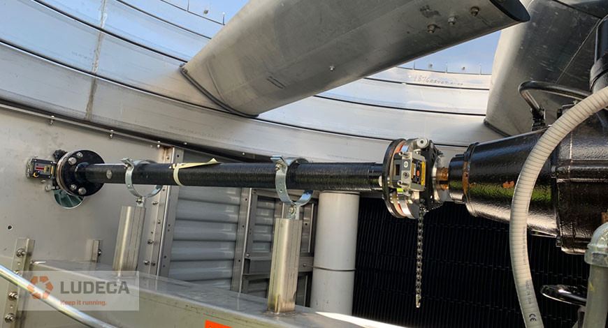

Picture 1
Generally speaking, a spacer shaft (spool, spider, jackshaft, or whatever you want to call it), is a coupling of some kind that spans more than 4″ or 101.6 mm between its flex planes. My goal in this blog is to provide five simple tips to help you align spacers without getting into the mathematical process. I’ll save those questions for the engineers. Keep in mind, these are suggestions for laser alignment of spacer shafts.
Spacer Shaft Tip 1:
Try to make sure you can square the two sensors to one another. By either using the inclinometers, lasers to targets, or really good eyesight – it tells you a lot if your sensors square up to one another. This seems like a simple or obvious tip (which is why it’s the first one) but, this also provides you with an indicator for TIP 2!
Spacer Shaft Tip 2:
There are two primary ways of aligning spacers: the Two-Step Method and the Single-Shot Method. Now that you can determine how bad your misalignment is – you can choose the method that fits best. The single-shot method is typically done when the alignment isn’t grossly out and the sensors would be mounted on the far ends of each spacer component. The two-step method is used when there is a significant amount of angle or offset to correct. The sensors should be mounted across each flex plane of the spacer individually to close the angle at each.
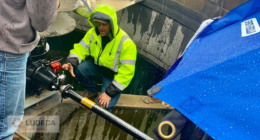

Picture 2
Spacer Shaft Tip 3:
Soft Foot. If you are following our 5-Step procedure you probably understood that I went a little out of order. However, we needed to know which components we were moving first, right? Now that we have a plan we have a procedure. Soft Foot matters, and it should be corrected and fall within the allowable tolerance. Use this time to also correct any challenges that can be identified visually (clean the base, good shims, etc.) You may want to take a look at our Soft Foot Find and Fix Procedure for an outline of types of Soft Foot including causes and corrections.
Spacer Shaft Tip 4:
Know your tolerances. There are 1,001 blogs and articles on spacer tolerances on the web. The best thing you can do is know what your tolerances are for that specific alignment. Yes, spacer tolerances can be more forgiving in terms of the required corrections at distances. However, there are many ways to represent those spacer tolerances. You could have a specification that is Angle/Angle or Offset/Offset or a combination of those. Make sure you are aware of the required values and representation.
Spacer Shaft Tip 5:
Patience. Don’t rush to get it done. Do it right so you don’t have to do it again.
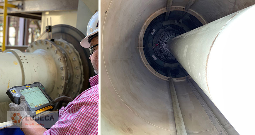

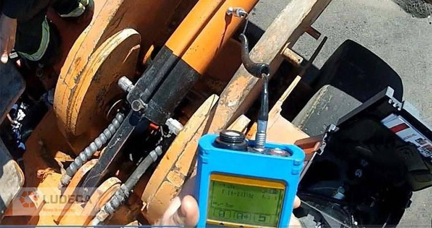
Picture 3 and 4
So, when you find yourself facing a spacer shaft, spool piece, or jackshaft, take a deep breath and follow the same rules of alignment that experience has taught us. I would also like to thank Joel Chapman from Entech Sales & Service Inc. for a lesson in cooling tower alignment in the rain (the umbrella was for me, not the laser, it was very nice of him – picture 2). And, thank you Richard Armstrong of TRACE Reliability, a LUDECA, INC. solutions provider who makes our customers a priority. He shared pictures 3 and 4 of an ID Fan in Louisiana that measured 289” inches from sensor to sensor.
by Diana Pereda
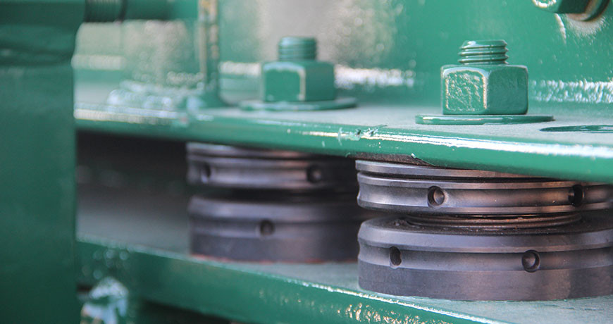

Adjustable chocks have been around for years and are a useful way to accomplish parts of machine mounting and alignment. In some circles, they have either a great or bad reputation. A lot of that reputation may depend on the application and how the chocks were installed.

Adjustable Chocks vs. Shims
First, let’s discuss why a company might want to use an adjustable chock for machine mounting, instead of shims:
- Adjustable for height. This means not having to stock lots of shims, in different sizes and thicknesses, to accomplish vertical adjustments in alignment.
- Spherical top part. This accommodates issues with feet not being parallel (up to 4 degrees for some manufacturers) with the foundation or skid which eliminates the need for step shimming.
- Easy Soft Foot corrections. When an air gap is found, simply fill the gap by adjusting the chock to fill the gap. (Zero Soft foot)
- Reduced inventory. Instead of several shims in a kit for each piece of equipment, just reuse the existing chock for adjustments.
Now, let’s discuss why a company might not want to use an adjustable chock for machine mounting, instead of shims:
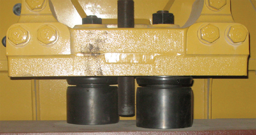
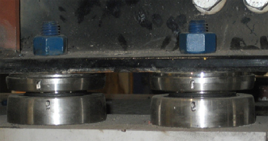
- Lack of contact surface between mounting foot and base. How can this round element take the place of a full-footprint shim for secure mounting?
- Transmission of Energy. Without the solid contact of that full-footprint shim, the energy will never be transmitted to the Inertia Block in the base; therefore, the equipment will shake itself to pieces.
- Locked up chock. Once they have been in service for a while, they lock in place and have to be replaced for future alignments.
- Loose chock. Upon inspection, the chocks have been found to be rotated down under the foot, and there is a gap/Soft Foot condition.

The Cons of Adjustable Chocks
By looking at each of those concerns, answers can be found for how to mitigate the concern and better understand how adjustable chocks can (and cannot) be used. The design and engineering of these devices make them suitable for most applications, but not if selected and used incorrectly.
For the issue of lack of surface area under a foot to the mounting base, looking at the product catalogs show any number of configurations to increase the surface area. Using more than one at each foot, or having two under a foot but staggered. The simplest rule to use is to use the largest chocks that can fit, but with a catch. The top surface must cover at least 75% of the surface area of the mounting foot, and the bottom surface must have 100% of its surface area in contact with the base. Both of these surfaces must be clean.
This leads to the next issue, the transmission of Energy. If the correct size of the chock is selected, and the above rule for coverage is observed, then the Energy will transmit through the body of the chock just fine. The other thing to watch for is cleanliness. Both the bottom of the mounting foot and the top of the base should be clean – reasonable steel-of-the-truck finish (corroded, excessive mill scale, or moon crater need attention, with a minimal primed surface for corrosion purposes. Any amount of paint, dirt, or debris can make for an uneven surface that could result in the bottom of the chock not sitting squarely. Sometimes, a bit of light sanding can go a long way towards promoting proper machine mounting. Check with chock manufacturer for surface finish recommendations.
Now, for the locked-up chock. Oftentimes, comments are made that the machine being aligned is unable to be lifted by the adjustable chock. This is a misconception. The threaded chock is designed to lock under load. It is NOT designed for lifting or lowering the equipment. Normally, equipment that is designed correctly will have vertical jack bolts, and this is what is used to establish the correct elevation for the machine, or, in their absence, use a hydraulic pancake jack or other suitable lifting devices. Beyond that, finding the chocks unable to rotate after being under a piece of equipment can usually be attributed to dirt and debris in the threads. It is a very common practice to lift the equipment on the vertical jack bolts just enough to remove the chocks. Thorough cleaning in a general solvent can remove the particles that restrict movement. After the cleaning, a thin coat of appropriate lubricant (often a specific compound recommended by the chock manufacturer) will help ensure movement. Protecting the cleanliness of the chock after alignment can be accomplished with a heavy protective spray. Anything that seals moisture and debris out is good, as long as it does not trap moisture (just to note: whatever you put on it will need to come off at some point to allow the chock to be reusable – be judicious or better yet contact your chock supplier).
Lastly is the concern of loosened chocks, which has been a topic of much discussion lately. The easiest way to explain this problem goes back to proper training. The technician performing the alignment needs to be mindful of how an adjustable chock is designed to work. The function of that chock is to support the machine. Prior to torquing the hold-down bolts, the machine needs to be resting on the chocks, not on the jack bolts.
The procedure boils down to using the jack bolts to establish the correct elevation, spinning all of the adjustable chocks up to firmly contact with the bottom of the machine, and then perform the final tightening. (Fit all chocks at the same time!!) Back off all lifting and lateral adjustment jack bolts FULLY, then tighten the anchor bolts to the proper torque in the sequence specified by the equipment OEM
Do not tighten the anchor bolts with the jack screws or lifting bolts under load!
The purpose of adjustable chocks is to facilitate proper mounting of equipment, more efficient alignment operations, and a viable replacement for traditional shims. While they might not work for all applications, with proper implementation chocks can work for 90-95% of applications where larger spacing between the machine feet and the mounting base is required; rather than inserting a big pile of shims, a chock can make life easier for the technicians performing realignment. This requires an open flow of information from the design and installation of the equipment, all the way through to the day-to-day maintenance.
This post was written in collaboration with www.machinerymountingsolutions.com
by Diana Pereda