While in Louisville, KY after the #SMRP19 conference, I took a tour of the Angel’s Envy bourbon distillery and was thrilled not only by their fine bourbon finished in port wine barrels but by their attention to safety and unique promotion of safety all around their clean facility. Their clever “Heaven can wait. Safety first” statement obviously applies to all maintenance activities but in this particular case, shown in my photo, it was used to emphasize the importance of lock-out and tag-out procedures, also known throughout our industry as LOTO.
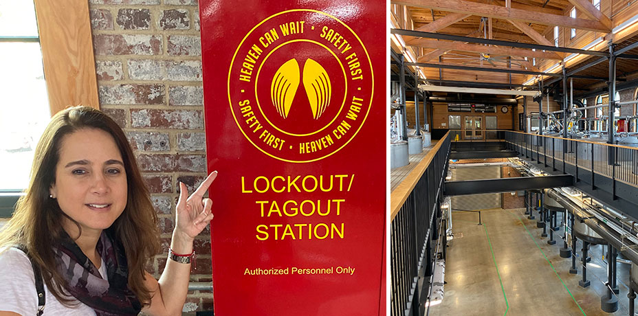
It reminded me of what we assiduously preach in all of our training courses: always lock out and tag out your machines before beginning any alignment procedure or balancing procedure.
Unlike ultrasound testing, acoustic lubrication or vibration analysis, all of which check machine or facilities condition while up and running, alignment and balancing require machines to be shut down and properly locked out, to adhere to all safety regulations. Only then can the components be mounted on the shafts. This ensures the safe rotation of the shafts and alignment corrections to be made without risk of injury to maintenance personnel.
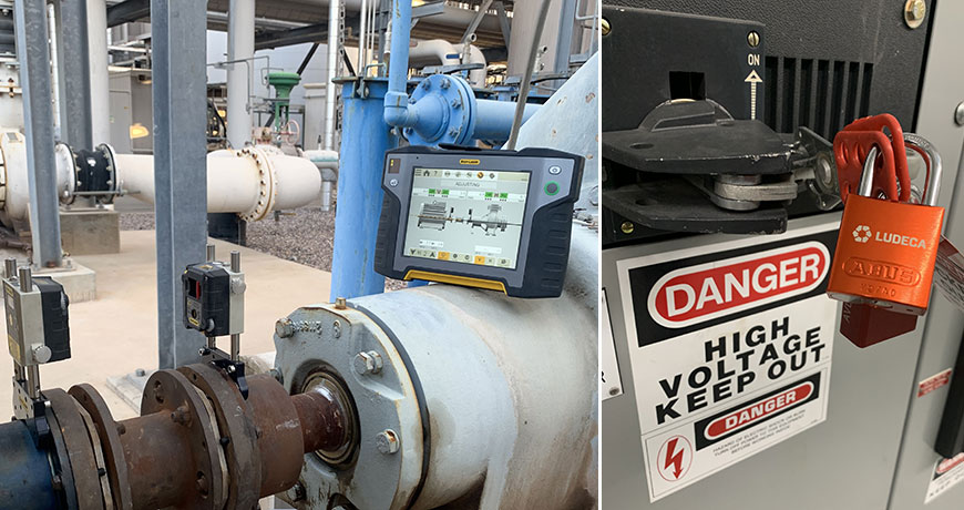
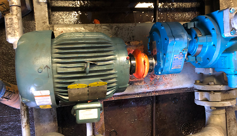
Thank you, Brian Franks with JetTech Mechanical for these great field photos featuring the Easy-Laser XT770!
I can’t stress enough the importance of safety during service or maintenance of machines and encourage you to develop more ingenious slogans like “Heaven can wait. Safety first” to draw more attention to this important concern within your plant.
Here are the six steps to follow for proper LOTO per OSHA 3120:
1. Prepare for shutdown;
2. Shut down the machine;
3. Disconnect or isolate the machine from the energy source(s);
4. Apply the lockout or tag-out device(s) to the energy-isolating device(s);
5. Release, restrain, or otherwise render safe all potential hazardous stored or residual energy. If a possibility exists for reaccumulation of hazardous energy, regularly verify during the service and maintenance that such energy has not reaccumulated to hazardous levels; and,
6. Verify the isolation and deenergization of the machine.
Source: Control of Hazardous Energy Lockout/Tagout. OSHA 3120 – 2002 (Revised)
A personal note for Bourbon lovers: if you haven’t already, try pairing dark orange chocolate with your favorite bourbon, what a delicious combination! Heaven can wait. Please drink responsibly.
by Ana Maria Delgado, CRL
Compressed air is one of the three highest cost utilities in use at your plant. It is also one of the least maintained in terms of system leaks. Leaks are expensive and wasteful, but most often ignored. Leaks may occur anywhere in your compressed air system. Here’s our list of top ten most common leaks:
- Connections on air supply lines (pipes)
- Quick couplers
- Filters
- Pneumatic cylinders
- Pressure regulators
- Air dryers
- Isolation valves
- Control valves
- Automatic drain traps
- Air separators
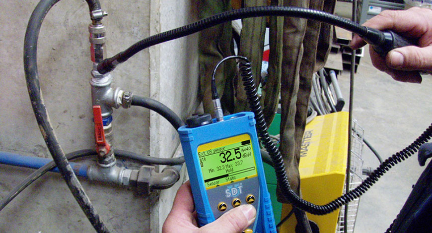
Finding and fixing these leaks is an easy way to reduce energy costs, but finding them is not easy because of background noise. A good quality ultrasonic detector can hear turbulence despite the ambient noise of the factory floor.
Download our LEAK SURVEYORS HANDBOOK and learn how to reduce or eliminate wasted compressed air with ultrasound through effective leak detection and repair.
Source: Ultrasound Leak Surveyor’s Handbook by SDT International.
by Diana Pereda
A route for vibration programs is the order in which machines that need to have vibration data collected on them have that data collected. To be able to optimize the data collection time and effort, the best practice is to have multiple routes. The machines in the route should be listed in a strategic and time saving list. If you were walking through the plant, which machines would be reached first, second, third, and so forth. The order of the routes themselves is very important as well and the time it takes to gather the data. If some machines (such as slow speed gearboxes) take a lot longer to collect data on, then perhaps a separate route might be needed just for them.
If the routes are not in a logical order then additional time is needed on the instrument to select the correct machine to start data collection. While 10 seconds might not seem that long to select the correct machine, if you have 200 machines on a route it could easily take an additional 30 minutes to finish that route if it is not logically configured. Data collection on that one route each month for the entire year could quickly turn into 6 hours of wasted time. Most plants have multiple routes and this wasted time figure could increase very quickly.
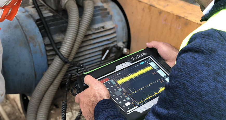
Routes are only the list and sequence of the equipment and do not hold any data themselves (within the VibWorks systems) and can therefore easily be deleted and re-created as many times as needed.
Reviewing your routes yearly could assist in eliminating wasted time.
by Diana Pereda
Problem
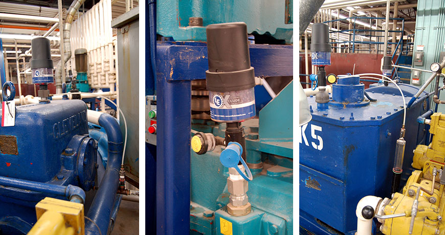
Dirt particles as small as 5 microns can easily damage bearings and gears in equipment. Unfortunately, gearbox vents and hydraulic breather caps only prevent particles larger than 25-45 microns from being ingested into machinery from the surrounding air. As a result, those large particles are broken down into much smaller particles resulting in premature equipment damage. For example, one teaspoon of dirt in a 55 gallon drum of lubricant can create one billion particles that are 4 microns or larger in diameter in that same drum. Imagine how much damage this can cause in equipment, leading to unwanted maintenance downtime.
Additionally, these vents and caps provide no protection from moisture ingress into equipment. Water is one of primary defect sources for industrial machinery.
Solution: Install good quality desiccant breathers on your equipment
A good quality desiccant breather has a 3 micron filter as part of the design to help prevent harmful particles from being introduced into equipment. As a result, premature equipment failures, loss of capacity and unneeded maintenance expenses will largely be prevented.
Additionally, desiccant breathers provide an insight into the equipment health through how the desiccant is being spent.
It is very important to have good quality desiccant breathers installed on equipment to prevent the introduction of equipment defects and help improve your return on assets.
Desiccant Breather Assessment
- If the top of the desiccant breather is pink there is an internal moisture source from the reservoir headspace.
- If the bottom of desiccant breather turns pink first then there is an external moisture source from the outside environment.
- If the desiccant breather turns amber or brown instead of pink, then it is likely an indication of oil misting.
- If the breather has turned completely pink then the desiccant is spent and the breather is at full water saturation.
- Reservoir water content: If the breather changes quickly from blue to pink when first installed, then the breather is likely working to remove water already in the system. It may take two to three breathers to dry the headspace before the breather begins operating normally.
- Sizing: If breathers continue to spend quickly, the size may not be appropriate for the application.
Things to check if your breather is not spending at all
- Dry Environment: If the environment has been abnormally dry there may not be enough ambient moisture for the silica to adsorb.
- Breather Size: The breather may be larger than what is required for the system. Check the recommended system sizing. The breather should be changed after one year, regardless of visible condition, to renew particle filtration.
- Intake Holes: Check that the proper number of plugs have been removed. Instructions on the breather packaging indicate how many holes are needed for various air flow requirements.
Note: The actual color changes above will vary depending on the supplier of the desiccant breather. All breathers will have some type of color change indicating condition. The above colors are applicable to two well-known desiccant breather manufacturers.
Desiccant Breather Air Vent Plugs
- Some combination of air vents should always be pulled depending on the air flow in the machine. This is a common mistake when installing breathers.
- If the CFM is greater than 12-16 CFM you should pull all of the air vents from the breather.
- When selecting a breather, always select a model with a CFM rating greater than the CFM requirements of the application.
- Breathers should not be selected by the size of the tank or reservoir. Breather size is always determined by the maximum fluid movement in/out of the fluid reservoir.
- Not all equipment, for example gearboxes, may specify a CFM value. If needed you can use this rule of thumb o calculate the CFM and select the correct breather for the application:
7.5 GPM = 1 CFM.
CFM = GPM/ 7.5.
Learn more about Lubrication Best Practices and desiccant breathers from Paul Llewellyn at our Rethink Maintenance Training Roadshows
by Diana Pereda
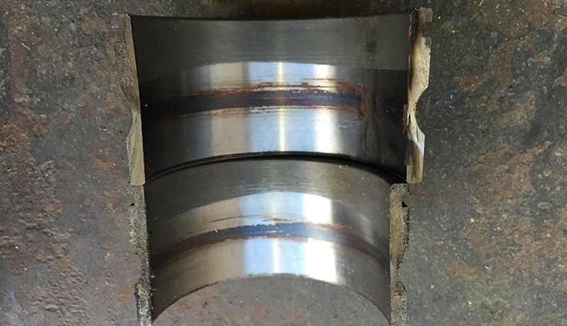
- Prevent metal-to-metal contact (which creates wear particles) by using condition-based lubrication through ultrasound. Ensure the proper oil viscosity and additive package is selected and that the bearing load does not exceed its design capacity through proper installation, alignment, balancing and operation.
- Use desiccant breathers.
- Adopt an aggressive fluid management program that establishes acceptable ISO cleanliness targets for new oil by machine type. Take care to use methods of adding and sampling oil that minimize contamination ingress. These include quick connect couplers and point-of-use filtration. Install an oil recirculation system to remove particles as soon as they are created and introduced.
by Yolanda Lopez
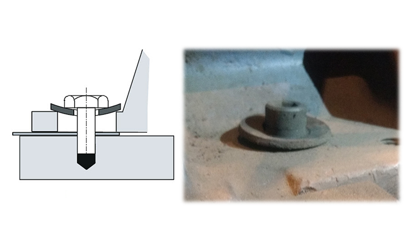 Often, maintenance departments invest in good quality Bolts and Nuts (Grade 8), but neglect to do the same with flat washers. The importance of a good washer cannot be overstated. If you use a typically thin Grade 2 (or worse) flat washer under the bolt head of the hold-down bolts of your machine, this washer will easily be distorted or warped into the hole in the foot upon tightening the anchor bolt. This is particularly true if the difference in shank diameter of the bolt and hole diameter in the foot is significant. This will often be the case when the hole in the foot has been enlarged to overcome a bolt-bound problem. The result of having “dished” washers is that when the anchor bolts are tightened after completing the alignment, the washers will try to center themselves in the hole in the foot and in doing so will pull your machine out of alignment again. This effect is virtually impossible to overcome, resulting in a badly misaligned machine after you just did a good alignment!
Solution: Always discard warped washers and use high quality thick flat washers that will not distort or warp into the hole. This will allow the washers to do their job of supporting the bolt head’s load on the surface of the foot.
Take a look at our Shaft Alignment Tools!
by Yolanda Lopez
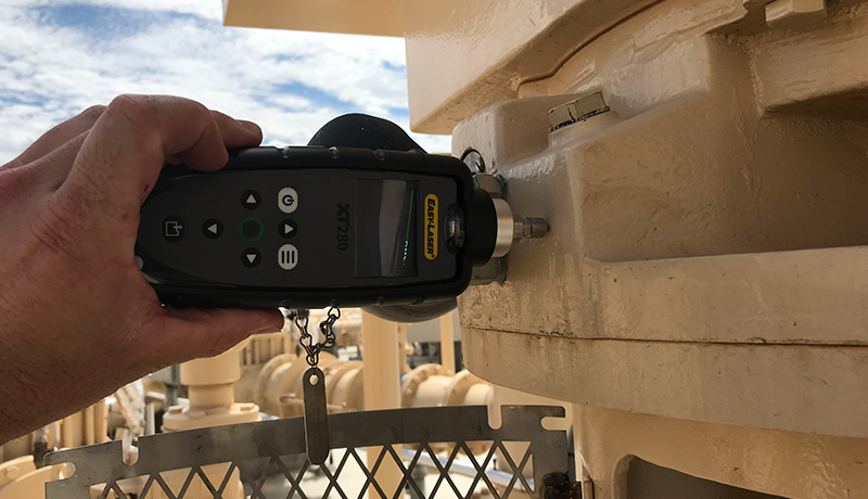 An overall level is a single number representing the amplitude of a vibration measurement. Overall values can be derived many different ways. You should be very cautious when assigning generic or the identical alarm values to your equipment. Similar machines can operate at different vibration levels. The individual characteristics of each machine should be taken into consideration when setting valid alarm levels. Even a simple vibration check revealing acceleration, velocity, unbalance or bearing noise can help you find and prevent equipment faults. You don’t need a sophisticated system for this; just a simple but good handheld tool (such as the EASY-LASER XT280) can help you with this.
by Ana Maria Delgado, CRL
Compressed air is the fourth most commonly used source of energy in industry. Walk through any facility and see miles of pipe transporting this house-made energy source to its point of use. On this journey its fate is undecided. Will it arrive to deliver the intended value? Or is it lost along the way?
Why Do We Tolerate Leaks?
On average, 40% of compressed air goes to satisfying the false demand of leaks. Why do we tolerate this waste in an otherwise efficient economy? Lots of reasons.
- Low Safety Risk?—Compressed air Leaks are rarely considered a risk. Odorless and colorless, they don’t make a mess on the floor, and we can’t hear them over plant noise.
- Lack of Education—Many believe compressed air is free. Yet a leak costs a thousand times more than lights that are left on.
- Complacency—The reliability culture does not always extend to the compressor room. Energy efficiency must be written into an organization’s aims and objectives.
Facts and Figures Don’t Lie.
Air is free. Compressed air is not. It requires another energy source to compress it. How much energy? Here’s the cost breakdown of a typical compressor system:
- 13% CAPEX
- 12% Maintenance
- 75% Energy
A small compressed air leak can cost $2,000+/year. Consider that hundreds of leaks may exist in your facility. What are you waiting for?
Leak-Management Solution
Manage your leaks with ultrasound. Their turbulent flow produces sounds that generate peaks in the 35kHz to 40kHz range—exactly where SDT’s ultrasound detectors are engineered to perform. SDT pinpoints leaks at their source, regardless of background noise.
 Use our Airborne Ultrasound Leak Management: Find-and-Fix Leaks, and start reducing waste plus save money!
Download our Leak Surveyors Handbook to learn more!
by Yolanda Lopez

MYTH: “All Soft Foot can be corrected by proper shimming.”
TRUTH: Soft Foot is Machine Frame Distortion. This can sometimes be caused by problems not easily fixable by shimming, like pipe strain, which can only be properly corrected by adjusting the piping and interface with the machine. A good laser system with positional change monitoring capability (such as EASY-LASER XT770 with Easy-Trend) is the best way to detect and measure the effects of pipe strain.
Watch and learn more about Soft Foot!
by Yolanda Lopez
Is it bearing information, number of poles, frame size, number of gears, impellers, blades, horse power, operating voltage, motor type, manufacturer, number of belts, sheave size, or tooth count? Nope! None of the above.
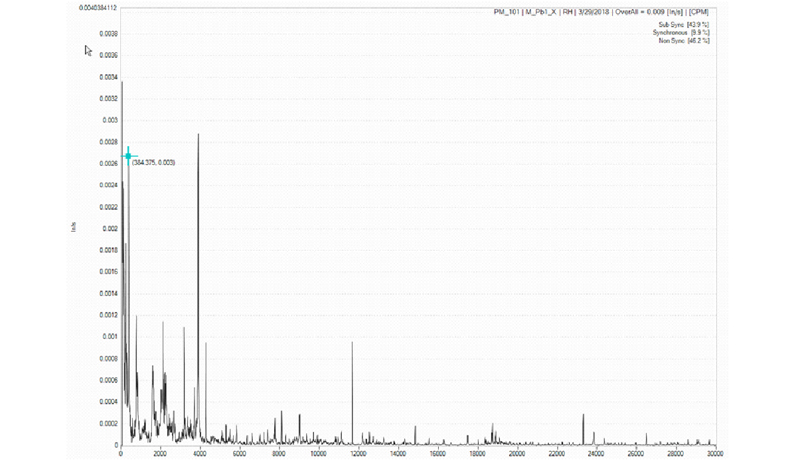
All of the above information is great to have when analyzing vibration data, but the single most important item that is always required is the running speed of the equipment.
Not knowing the true running speed makes vibration analysis impossible for determining the proper defect to be reported. For example, if the speed was recorded at 1,780 RPM, but the true speed was 3,560 RPM and a high peak at 3,560 RPM is present; it could lead the analyst to believe that the 2× turning peak is related to another issue. Having the proper running speed of the equipment will assist the analyst in making the correct diagnoses for the equipment.
Once the correct turning speed has been identified the spectrum can be broken into three types of energy: sub-synchronous, synchronous, and non-synchronous.
Having this information available can assist the analyst when analyzing the vibration data.
Related Blog: Finding the running speed of a machine
by Yolanda Lopez
MYTH: “Pipe Stress makes the alignment difficult.”
TRUTH: Pipe stress does not have any significant influence on the alignment unless you make corrections on the machine with the piping attached. In most alignment, the corrections to eliminate misalignment are performed on one machine only, typically the one that is easier to move. In a pump-motor set, the corrections are done on the motor. If there is sufficient room to shim and move, excellent alignment can be achieved regardless of how much pipe stress there is on the pump. Of course, pipe stress is undesirable and should be eliminated prior to the alignment.
Watch and learn more about Pipe Stress
by Yolanda Lopez

Are you adding grease to a bearing and not hearing any changes from your ultrasound equipment? If so, start wondering where the grease is going. It is a fact that if grease gets into a bearing the ultrasound decibel will either go down on a bearing that needs grease or go up on a bearing that is already over-lubricated.
Look for a blocked grease tube. Grease may be going into the windings on an electric motor. Do you see grease on the tube of the grease gun? Maybe a greaseable bearing was replaced with a sealed bearing at the motor shop after a repair. These are just some of the things you need to consider if you get no ultrasonic decibel change after injecting grease to a bearing.
Download 5-Step Acoustic Lubrication Procedure
by Yolanda Lopez
We often hear “Coupling alignment tolerances provided by the coupling manufacturer are good enough for shaft alignment.” or “There’s no need to align your machines tighter than the tolerances allowed by your flexible coupling.”
This is wrong because good quality flexible couplings may be built to withstand much more misalignment than what is good for your connected machines, in terms of the vibration and other forces created. Bearings and seals may wear out and fail faster than a highly misalignment-tolerant coupling. The reason for this “extra misalignment capacity” in flex couplings is that they may need to withstand significant positional changes resulting from thermal growth or dynamic load shifts. This lets you deliberately misalign machines to “cold alignment” targets.
Take a look at our Shaft Alignment Tools
by Yolanda Lopez

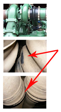
Every analyst develops their own process for analyzing vibration data. This is generally learned from others, being around to observe or communicate with, or from training the individual receives. Often, the person collecting the data will be the same person that analyzes the data. The process could include that during the data collection the person not only uses the vibration data collector but also collects physical data from their senses such as sound and smell to see what is going on with the equipment. They ought to look for material under the coupling guard to see if an elastomer coupling is shedding pieces, which may indicate misalignment; look at the oil level if possible for signs of oil leakage; look at the mechanical seal area to identify other leakage. Once data is collected one would generally look for anything outside of established alarm levels, look at the spectrum to see where the highest amplitude peak is at, look for other high amplitude peaks or groups of peaks and harmonic families, and look for sidebands around peaks to help in identifying the source. You would also look for the direction of the highest vibration. Examine the historical data too: you would want to look at the rate of change to determine how quickly failure is approaching. Also never, never forget to look at the time waveform as all data comes from the time waveform. I try to look at the time waveform in the raw units of the sensor as that can verify what you may be seeing in the spectral and give you a greater understanding of just how bad a problem you may be facing.
If you need a solution to help ease this process, consider our BETAVIB vibration analysis systems.
by Yolanda Lopez

When the breakdown/repair cycle becomes routine, you can bet money is being wasted. The psychology of manufacturing (if we can call it that) is very much overlooked.
Q: What if it was a personal affront to everyone in the plant, management, production, and maintenance, for a machine to break down? Seriously. What if everyone viewed it as a personal failure when a machine failed unexpectedly? Do you think the necessary attention would be given to it? That might be revolutionary.
Of course, if too much time and effort are put into something, the cost will exceed the return, but if the necessary serious attention is given to an operating asset by EVERYONE, the next excellent idea that improves reliability could come from anyone.
“Ownership” is something we know to be beneficial in a manufacturing facility. We know that the more “personal” everyone feels toward the assets, the better they take care of them and the more creative they are about caring for them. When we feel that personal attachment of ownership, we are more forthcoming with our efforts and supportive of the efforts of others who share our valuation of the assets.
With this in mind I offer the following suggestion in order to tap into that inherent pride of ownership and personal attachment that many have to the company and assets of their occupation: LET EVERYONE SEE HOW UGLY IT IS!
Hang a sign on a machine that failed and shut your plant or process down. The sign should read,
This machine FAILED and shut our plant down:
Failed: August 30th, 2011
Failed: May 4th, 2015
Failed: January 19th, 2017
Failed: August 11th, 2018
And keep adding the dates. This way the bad actors become obvious to everyone, and even the MTBF will be obvious. The absence of a sign on a machine could then be as informative as the signs with dates.
If you can succeed in creating ownership of reliability that cuts across department lines, the benefits could be enormous. Failures come from all directions: Operations, maintenance, engineering, management, and procurement. Let everyone see the ugliness of it and encourage everyone to pull together to make it beautiful (or at least more attractive.)
by Yolanda Lopez
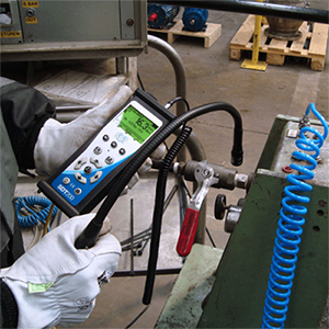
The diesel engine is the heart of heavy construction equipment and replacement costs are in the millions. Ingress of dust due to leaky air intake systems shreds components in short order. The SDT TIGHTChecker quickly and easily pinpoints leaks in the air intake system.
Dust is no friend to a diesel engine. But when the integrity of the air breather and turbocharger is compromised by leaks, microscopic grains of silica and other contaminants are sucked inside. There, they wreak havoc on the engine’s internal components costing organizations millions of dollars in premature wear and downtime.
Worse yet, you may not even realize you have dust ingress unless you are conducting regular oil analysis. These leaks are nearly impossible to find using conventional methods. A visual inspection takes hours and is often unsuccessful. Production does not have the patience to wait. They need that asset back in the field, leaks or not.
But what if there was a way to identify those leaks in minutes, instead of hours? SDT Ultrasound Solutions teamed up with mining giant Rio Tinto in Labrador, Newfoundland to devise a simple procedure for identifying turbo leaks in the engines of their huge loaders.
Using SDT ultrasound technology, a transmitter is placed inside the air filter basket. The high-frequency sound waves are contained inside the piping unless there is a leak. Any microscopic air gap in the pipe is instantly recognized by the handheld flex ultrasound detector.
An 8-hour inspection that often ended in frustration is now a worldwide success story that continues to save Iron Ore Company of Canada $8 million per year.
by Yolanda Lopez
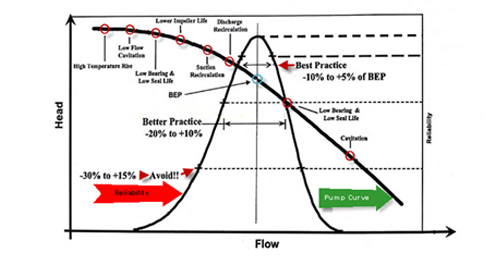
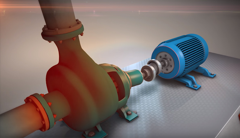
Centrifugal pumps have a specific design point at which they operate most efficiently. This sweet spot is known as the BEP (Best Efficiency Point) which provides the design engineer with the required flow and pressure while also providing the best efficiency. If the pump has been specified incorrectly or is placed into a system that doesn’t have the proper system head, the pump will become a reliability problem child. When a centrifugal pump is placed into a system without the required system resistance, the pump will run off its curve to the right, resulting in early bearing and mechanical seal failures and impeller damage caused by cavitations. If the pump is placed into a system with excessive system resistance, or, as frequently happens, the pump discharge valve is throttled early, bearing and seal failures occur along with impeller problems caused by discharge recirculation. Best practice dictates that the pump be specified and designed to operate within +5% to –10 % of its designed BEP. This will result in lower operating and maintenance costs and a happy pump.
by Yolanda Lopez
Guest Tip by Bob Dunn from I&E Central, Inc.
In some environments, reflected sounds can make it difficult to locate a leak. If you are in a confined area (a smaller room, or beneath/inside a machine), the leak can seem to be almost anywhere. A good ultrasound leak detection solution is to adjust the sensitivity downward. Ultrasonic sounds will reflect but lose energy each time they reflect. By reducing sensitivity, the reflected sounds drop into the background, allowing you to locate the actual source of the leak.
Note that SDT inspection tools have separate adjustments for sensitivity and headphone volume, so you can manage sensitivity without affecting your ability to hear!
Download our Find-and-Fix Leaks with Airborne Ultrasound Infographic!
by Ana Maria Delgado, CRL
There are many different reasons to consider and implement an online vibration system. Some of the key reasons are:
- The equipment is critical to production.
- The equipment has a long repair time.
- The parts for the equipment have a long lead time.
- The equipment is not easy to access.
- The equipment is in a remote location.
- Equipment failure could endanger the environment or people.
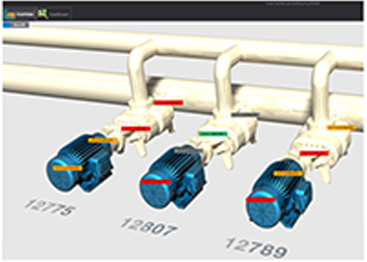
Online systems like the CORTEX by BETAVIB allow not only vibration to be monitored but also many additional parameters (such as speed, temperature, pressure, and flow, to list just a few), all of which can also be monitored and recorded. In addition, a customized overview can also be created to allow anyone to quickly monitor the health of the equipment using red, yellow, and green alarms that will indicate if an issue is present.
The CORTEX Monitoring System (CMS) is a cost-effective, scalable solution, dedicated to the prediction of asset failure and the prevention of catastrophic failures and costly repairs. This innovative system will help you optimize your performance by monitoring the condition of your valuable assets with highly accurate diagnostic tools.
by Yolanda Lopez
Reposted from People and Processes, written by Jeff Shiver CMRP, CPMM, CRL
Do you find yourself wondering why your employees haven’t taken the initiative and approached you for additional training? Well, they must not want the extra training, right? Wrong! Sometimes, employees do want training, but they just don’t ask. Here’s why:
1. THEY HAVE FEAR OF REJECTION
People don’t like to be told no! The majority of employees don’t understand the organization’s vision, goals, brand promise, or key initiatives.
2. THEY FEEL UNSUPPORTED
Employees get worn out from a culture of mediocrity being tolerated, commitments not honored, and requests being ignored.
3. THEY DON’T KNOW HOW TO ASK
Operators, Mechanics, Planners, and even Managers may not understand how to equate the returns of training.
4. THEY DON’T KNOW WHEN TO ASK
Many employees don’t know when there is flexibility within the budget.
5. THEY ARE AFRAID OF BEING NEEDY
If no one else is asking for training, then why should they expect to be treated differently?
6. THEY FEEL AWKWARD OR UNCOMFORTABLE
There must be a commitment for development and the line of communication should be open.
7. THEY DON’T FEEL CHALLENGED
They may be topped out and let with nowhere to go from a promotional perspective.
8. THEY DON’T KNOW WHAT THEY DON’T KNOW
When people have never been exposed to anything else, they don’t know what else is possible.
Keep these things in mind the next time you offer training, or feel that your employees should ask you if they want it. A better approach may be discussing this with your employees individually.
Check out LUDECA training offering for alignment, geometric measurements, vibration analysis, balancing and ultrasound.
by Ana Maria Delgado, CRL