Guest post by John Lambert at Benchmark PDM
Recently I have been seeing the P to F interval curve popping up a lot on my LinkedIn feed and in articles that I have read. It was a concept that I was first introduced to when I was implementing Reliability Centered Maintenance into the Engineering and Maintenance department at the plant where I worked at the time. It was a great idea, that if done correctly is a maintenance benefit. Why, because it’s cost savings and cost avoidance. Let me explain this.
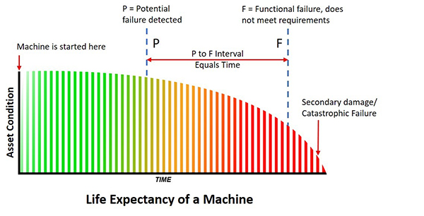
The P to F curve was used as a learning tool for Condition Based Maintenance. The curve is the life expectancy of a machine, an asset. The P is the point when a change in the condition of the machine is detected. The F is when it reaches functional failure. This means that it is not doing the job it was designed to do. For example, if it were a seal that is designed to keep fluids in and contamination out and is now leaking, it’s in a state of functional failure. Will this put the machine down? Probably not, but it depends on the importance of the seal and the application. This is an important point because the P (potential failure) is a fixed point when you detect the change in condition but the F (failure) is a moving point. Not all warnings of failure put the machine down very often you have options and time. Consider this: If I have a bucket that has a hole in it, it is in a functional failure state. But can I still use it to bail out my sinking boat? You bet I can!
Failure comes at us in many ways and obviously, we have many ways to combat it. If you detect the potential failure early enough (and it can be months and months before actual failure) it means that you can avoid the breakdown. You can schedule an outage to do a repair. It’s not a breakdown, the machine hasn’t stopped, it’s no downtime. This is cost avoidance and the plant can save on the interrupted loss of production because of downtime costs.
There are a lot of examples of cost avoidance and also of cost savings. For instance, at the plant I worked at we used ultrasound to monitor bearings. We detected a very early warning in the sound level and were able to grease the bearing and the sound level dropped. We saved the bearing of any damage, and we saved a potential breakdown so this is cost savings. Even if there is some bearing damage, the fact that we are aware of and monitor the situation lets us avoid any secondary damage.
It’s one price to replace a seal and it’s more if you have to replace a bearing in a gearbox. However, it can be very expensive to have to replace a shaft because the bearing has sized onto it and ruined it. Secondary, ancillary damage can mount up very quickly if you don’t heed the warning you are given with the P of potential failure. This warning of potential failure gives you time before any breakdown. The earlier the detection, the more time. Time to plan, and view your options. And what people tend not to do is failure analysis while the machine is still in service. A failure analysis gives you a great start on seeking out the root cause but starts right away, not when the machine is down.
Condition monitoring or as it’s often called Condition-based maintenance (CBM) does work. However, for me, there is a downside to this and I will explain why shortly. CBM is based on measurement, which is good because we all know to control a process we must measure.
Consultants (and I’m guilty) like to put labels on things and you may see:
1. Design, Capability, Precision Maintenance
2. CBM, Predictive Maintenance
3. Preventive Maintenance
4. Run to Failure, Breakdown Maintenance
For me, the P to F interval curve starts when the machine starts. That means Design and Precision Maintenance is not in the curve and this happens before startup. A small point but it takes away from the interval meaning.
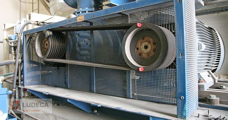
We use predictive maintenance technologies in CBM. Vibration, Ultrasonic, Infrared, Oil Analysis, NDT (i.e. pipe wall thickness), and Operational Performance. They are all very good technologies, yet it is a combination of cross-technologies that works best. As an example, vibration may give you the most information yet ultrasound may give you the earliest warning on a high-speed bearing. And then there is oil analysis which may be best for a low-speed gearbox. It all depends on the application you have which dictates what’s best for you. A lot of time and effort was placed on having the best CBM program and buying the right technology.
This, I believe, lead to the maintenance departments putting the focus on Condition-based maintenance! This I think is wrong because we still have failure. This means that CBM is no better than Predictive Maintenance. This doesn’t mean that I don’t recommend CBM, I do. To me, it’s a must-have but it does not improve the maintenance process because you still have machine failure. Machine failures fall into three categories Premature failure, Random failure, and Age-related failure. We want the latter of these. We know from studies that say that 11% of machine assets fail because of age-related issues. They grow old and wear out. This means that 89% fail because of some other fault. This is a good thing because it gives us an opportunity to do something about them.
These numbers come from a very famous study by Nowlan and Heap (Google it!) that was commissioned by the US Defense Department. It doesn’t mean these numbers are an exact reflection of every industry but the study but it has stood the test of time and I believe it has led to the development of Reliability Centered Maintenance. But let’s say it’s wrong and let us double the amount they say is age-related (full machine life expectancy). That would make it 22% and 78% would be the number of random failures. Even if we quadruple, it’s only 44% meaning random is at 56% and we are still on the wrong side of the equation. The maintenance goal has to be to get the full life expectancy for all their machine assets.
In order to get the full life expectancy for a machine unit, I think you have to be assured of two things. One is the design of the unit which includes all related parts (not just the pump but the piping as well). The other is the installation.
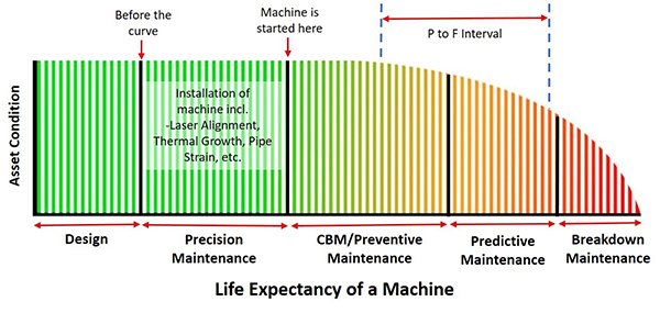
If you’re like me, and you believe that Condition Based Maintenance starts when the machine starts then you understand that there is a section of the machine’s life that happens before. You could make an argument that it starts when you buy it because, as we all know, how we store it can have an effect. However, what is important at this stage is the design and installation of the machine. In most cases, we do not design the pump, gearbox, or compressor but we do size them so that they meet the required output (hopefully). We do quite often design the piping configuration or the bases for example. All of which is very important but the reality is that maintenance departments maintain already-in-place machine assets. So, although a new installation, requiring design work is not often done, installation is. Remove and Refit is done constantly. And the installation is something that you can control. In fact, it’s the installation that has the largest influence on the machines’ life. The goal is to create a stress-free environment for the machine to run. No pipe strain, no distorted bases, no thermal expansion, no misalignment, etc.
Precision Maintenance was a term I first heard thirty years ago. It’s part of our M.A.A.D. training program (Measure, Analyse, Action, and Documentation). It’s simple, it means working to a standard. Maintenance departments can set their own standards. However, all must agree on it and adhere to it. This is the only way to control the installation process. This is the way to stop random failure and get the full life expectancy for your machine assets. The issue is that we do not have a general machinery installation standard to work to. Yes, we can use information from other specific industry sources such as the American Petroleum Institute (API) or the information from the OEM (both of these are guidelines) however nothing for the general industry as a whole. Well, this is about to change. The American National Standard Institute (ANSI) has just approved a new standard that is about to be published. I know this because I worked on it and will be writing about it shortly.
If you look at the life cycle of a machine, we need to know and manage the failure as best we can. If we only focus or mainly focus on the failure, we will not improve the reliability of the machine. We cannot control the failure. What we can control is the installation and done correctly this will improve the process giving the optimum life for the machine.
I sell laser alignment systems as well as vibration instruments. If a customer were to buy a vibration monitoring tool before they bought a laser system. I would think their focus is on the effect of the issue, not the cause. What do you think?
by Ana Maria Delgado, CRL

In the world of industrial maintenance, where every alignment can make the difference between smooth operation and unexpected breakdowns, the tools you rely on must perform flawlessly. For users of Easy-Laser products, Ludeca’s ISO/IEC 17025:2017 accredited calibration laboratory delivers unwavering reliability. This accreditation confirms our lab’s expertise in producing precise, traceable results that meet global standards—giving you peace of mind that your equipment is calibrated to the highest level, ready to support your shaft alignments and keep machinery running efficiently day after day. Located in Doral, Florida, Ludeca’s calibration laboratory accepts all laser alignment systems made by Easy-Laser or Pruftechnik for calibration.
At its core, ISO/IEC 17025 accreditation is about proven excellence: it ensures our processes consistently yield dependable outcomes. For Easy-Laser systems, this means calibrations ensure accurate misalignment and soft foot measurements to prevent unnecessary wear and downtime. It’s a safeguard that aligns seamlessly with industry guidelines, such as ANSI/ASA S2.75, allowing your team to focus on proactive maintenance that extends equipment life and boosts efficiency, all without the worry of inaccurate or inconsistent measurements.
Ludeca’s commitment to this standard is no recent development; Ludeca has held the prestigious ISO/IEC 17025 accreditation for over 12 years, building on our legacy as the pioneers who first introduced laser alignment system to the U.S. market. This enduring dedication, paired with our close collaboration with Easy-Laser, ensures our calibrations are perfectly tuned to their innovative designs. In our advanced facility, equipped with specialized tools and protected environments, we treat every calibration as a step toward your operational success, reinforcing why partnering with us means choosing a leader in precision and service.
By aligning with Ludeca, you’re not just getting quality tools for reliability; you’re investing in a partnership that strengthens your entire reliability program.
Visit our Repair and Calibration webpage to learn more about our services. We strive to be your premier repair service and calibration provider!
by Diana Pereda
Threaded fasteners are the most used type of fastener. Many threaded fasteners are assembled with nuts and washers.

Thread Standards: There are many different types of threads used for fasteners in industry, designed to be used for different jobs. Threads used on fasteners are manufactured to industry-established standards for uniformity. The most common thread standard is the unified standard, sometimes known as the American standard. Unified standards are used to establish thread series and thread classes.
Thread Series: Unified standards are established for three series of threads, depending on the number of threads per inch for a certain diameter of fastener.
- Unified National Coarse (UNC) thread: Used for bolts, screws, nuts, and other general purposes. Fasteners with UNC threads are commonly used for rapid assembly or disassembly of parts and where corrosion or slight damage may occur.
- Unified National Fine (UNF) thread: Used for bolts, screws, nuts, and other applications where a finer thread for a tighter fit is desired.
- Unified National Extra Fine (UNEF) thread: Used on thin walled-tubes, nuts, ferrules, and couplings.
Thread Classes: The unified standards also establish thread classes. Classes 1A, 2A, and 3A apply to external threads only. Classes 1B, 2B, and 3B apply to internal threads only. Thread classes are distinguished from each other by the degrees of tolerance permitted. Classes 3A and 3B allow a minimum clearance and classes 1A and 1B allow a maximum clearance. Classes 2A and 2B are the most commonly used. Classes 3A and 3B are used when close tolerances are needed. Classes 1A and 1B are used where quick and easy assembly is needed and a large tolerance is acceptable.
Thread Identification is done using a standard method.
- Nominal Size: The nominal size is the approximate outer (or major) diameter of the fastener.
- Number of threads per inch (TPI): The TPI is standard for all diameters.
- Thread series symbol: This symbol indicates the Unified standard thread type (UNC, UNF, or UNEF).
- Thread Class Symbol: This symbol indicates the closeness of fit between the bolt threads and nut threads.
- Left-Hand Thread Symbol: This symbol is indicated by the letters LH. Unless threads are specified with the LH symbol, the threads are right-hand threads.

Thread Design: There are several types of thread design. The thread design depends on the purpose of the fastener. Power transmission threads are special threads that are used to move machine parts for adjusting, setting, and transmitting power. Three common power transmission threads are the square thread, acme thread, and buttress thread.
- Buttress Thread: has one side of the thread cut square and the other side cut at a slant. It has great strength along the thread axis in one direction only. This thread form is used to screw thin, tubular parts together.
- Square Thread: is the strongest and most useful of all thread forms. It is also the most difficult to make because its parallel sides must be accurately machined. Square threads are commonly used in precision measuring instruments, aerospace equipment and robotics due to their strength and ability to handle high-stress environments.
- Acme Threads: The Acme thread has replaced the square thread in most cases because it is easier to machine. Acme threads are commonly used in industrial machinery, power transmission systems, automotive industry, clamps and valves.

by Diana Pereda

Maintenance and reliability improvements don’t always require expensive or complicated efforts or Continuous Improvement (CI) projects.
Start with the “basics”:
- Do Precision Laser Alignment
- Do Precision Balancing
- Eliminate looseness by checking machine fasteners for proper tightness
- Use Precision Lubrication (correct lubricant type and quantity)
- Perform routine Machine Inspections
- Incorporate Condition Monitoring technologies such as vibration analysis and ultrasound testing
- Focus on critical assets before expanding your efforts within the facility
Basic maintenance and reliability functions are not always implemented or followed because of forced production and time constraints. Insufficient funding sometimes results in reduced training or bypassing essential maintenance tasks, giving the impression of cost savings; however, ensuring that your management team, engineering group, maintenance department, production and purchasing teams understand how these basic maintenance techniques directly impact equipment reliability will go a long way in keeping your equipment reliable from the beginning.
Watch our Reliability Matters: The Basics video for an overview of basic concepts to improve rotating equipment reliability and machinery health.
Who is most passionate about maintenance and reliability within your organization?
by Diana Pereda
When performing a Dynamic Balance procedure a few things should be considered:
1. Inspect the structure/mounts and ensure there are no cracks or loose bolts.
2. If driven via a belt drive make sure that the belt is in good condition and properly tensioned.
• Remember that the second harmonic of a belt frequency can be very close to the rotational speed of the drive.
3. Inspect the rotating element for the build-up and clean as necessary.
• Remember that even the slightest build-up (i.e., dust) can be the cause of an unbalance.
4. If the rotating element is a blower, count the number of blades.
• Frequently correction weights will have to be attached to the blades and therefore it may be best to use a fixed location method.
5. If the equipment is down when you arrive, replace the reflective tape or attach new tape as may be required.
• This will ensure accurate phase data.
6. When taking your initial phase data turn the averaging function off, if possible.
• Monitor the phase data for a brief time to ensure its stability. Doing this could identify potential problems.
7. Keep good documentation, keep written notes on what was found:
- Phase and amplitude data
- Number of blades
- Correction locations
- When weights were attached or removed
- How much weight was attached or removed
- Sensor placement
- Tachometer placement.
8. If the equipment is variable speed such as VFD drive or DC drive ensure that the speed is repeatable to within 5% or less run to run.
Download our 5-Step Balancing Procedure for a simple and effective procedure for doing field balancing!
by Gary James CRL

Visual inspections of equipment should always be completed during vibration data collection or the collection of any type of condition monitoring (CM) data. This important function is often overlooked and valuable information on the condition of your equipment is lost.
Looseness and many other conditions are commonly found as a result of a vibration analysis program. The source of these conditions should be corrected to improve the equipment’s reliability. Visual inspections can easily be completed on the machine while the data collector is acquiring the data. The visual inspection may reveal the source of these equipment issues. This will save time because future efforts will not be required to determine the cause of the issue.
Visual inspections may provide a confirmation to the analyst of the problem(s) uncovered by the vibration analysis program or other CM technology. It is important to diagnose and confirm problems to ensure accuracy in your CM efforts. Visual inspections may often provide the confirmation opportunity needed.
Safety issues are often uncovered by these routine visual inspections and can be corrected before an employee is injured. This could save a life and the resulting return on the investment is priceless!
by Trent Phillips

Every analyst has a few things they really don’t want to hear during the course of their work. These comments often indicate that proper maintenance activities have not been performed on the equipment, or convey unrealistic expectations of the analyst’s abilities. For instance:
- “It has always run like that!”
- “It really was making a noise before you arrived.”
- “We don’t have time to change the bearings. Just balance the machine so we can run it.”
- “How long will it last?”
- “Those bearings are brand new so I know they’re good.”
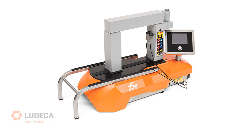
- “Yeah, we just use a torch to heat bearings to install them.” Use a SURETHERM induction heater with automatic demagnetizing to properly install your bearings.
- “We don’t have a bearing heater so we use a pipe and hammer to drive the bearing on.” Use a SURETHERM induction heater with automatic demagnetizing to properly install your bearings.
- “All we collect are overall vibration values, they tell us everything we need to know.”
- “It doesn’t take us long to change belts cause we just roll them on.” Very bad practice! Use a laser tool like the SHEAVEMASTER and loosen the feet of the motor before installing the new belts.
- “We don’t use no fancy alignment tool. All we need is a straight edge.” A recipe for disaster! Get a good laser shaft alignment system like the Easy-Laser XT770 —the money this will save in lost production and unnecessary repairs will more than pay for itself, not to mention the time saved for the analyst who can now dedicate himself to finding other more complex vibration problems.
- “My screwdriver does not confirm your analysis!”
- “You found the problem. Now go fix it.”
- “I didn’t realize you needed training.” Sign-up for a LUDECA vibration analysis training class.
- “I didn’t realize that this CM technology would create so much work.”
- “We need you to stop using that CM technology and turn wrenches this week.”
- “We didn’t realize you had identified and created a work order to fix that problem before it failed.”
No doubt you’ve heard a few more! Feel free to share them with us.
by Gary James CRL
Proper location is very important when collecting vibration measurements on a belt system. If possible, one reading should be taken in line with the sheaves and one reading perpendicular to them on each bearing. Vibration data resolution should be taken into account so that proper separation between belt and driver frequencies can be obtained. Care should be taken to ensure proper belt alignment as well. A laser pulley alignment tool provides the most efficient means to properly align belts. Another issue is how the belts are installed. Was the equipment loosened and the belt put on properly? Were the belts instead rolled on by force, creating potential issues? Have you ever seen a Vee belt running upside down? This is usually caused by the cording in the back of the belt being broken often caused by rolling on the belts. Are sheave gauges being used to check the sheaves for wear? In some cases, the cost of a belt is more than the cost of a new sheave. These are just some of the things to consider for proper installation, maintenance, and identification of belt-related problems.
Don’t just assume that belts are simple and do not require best practice actions for proper operation.
Don’t Forget To Inspect Your Belts! 9 Preventive Maintenance Tips
by Gary James CRL
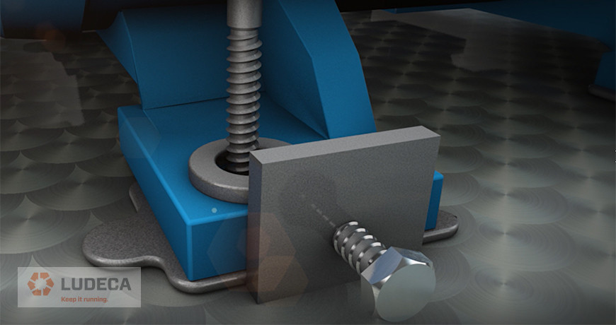
When moving machines for alignment, always use jackscrews. If you don’t have them, beating on the machine frame with a steel-face hammer is a lousy idea.
First, you run the risk of damaging the bearings, seals, and other delicate components in your machines. Secondly, you have little control over the magnitude of your moves. Thirdly, it’s unprofessional. If you don’t have time to weld or screw-on jackscrew assemblies, consider using a couple of carpenter’s pipe clamps, tensed against each other. This makes for a handy portable jackscrew arrangement that is safe, inexpensive, and offers you plenty of control. If this is not possible either, and you must hit the machine with a hammer, then at least do so with a plastic-face, shot-loaded dead-blow hammer.
How to Analyze Unexpected Results After Performing a Shaft Alignment Horizontal Live Move
by Ana Maria Delgado, CRL
- Shaft speed of machine being analyzed
- Type of bearings involved (sleeve vs. rolling element)
- Rolling element bearing part number(s) and manufacturer(s)
- Internal configuration of equipment
- Machine History
- Proper data collection location
- Proper sensor to use for data collection
- Proper data collection setups to ensure correct data is collected
- Is the primary energy sub-synchronous, synchronous or non-synchronous?
- If the time waveform is collected in acceleration then what is the “g” level?

by Gary James CRL
- Make sure the surfaces of the vertical posts are clean.
- Improve the contact between the vertical post and the crossbar by applying a light coat of Vaseline or grease to the contact surface of the vertical post.
- The temperature probe should always be placed on or as close as possible to the inner race or ID of the workpiece being heated.
- When possible make sure a second probe is placed on the outer race or OD of the workpiece being heated to also track the temperature of the OD, in line with the ID probe.
- For the most efficient heating, always use the largest possible crossbar that will fit through the ID of the workpiece being heated. Stacking of multiple crossbars is permissible.
- It is not a requirement that the workpiece must touch the crossbar(s). Just so long as the bar goes through the bore (ID) someplace.
- Most important of all is that the workpiece being heated always be automatically demagnetized. Any induction heater that does not do this automatically COSTS you money instead of saving it.
by Bernd Seidenthal CRL
Machines are like people. They all have certain similarities but are different in many ways. Two exact machines in the same operation may perform and respond quite differently.
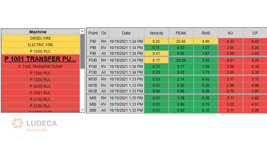
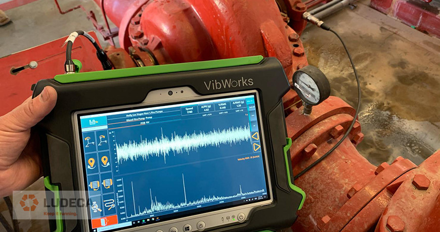
Setting alarm values for your vibration measurements is critical for the success of your vibration monitoring program. Alarms will help the analyst identify when conditions on the machine have changed and assist in identifying specific fault conditions. All of this makes the analysis much more accurate and easier. Additionally, this can reduce the amount of time required to analyze the vibration data collected. However, for all this to work the alarms must be set up correctly.
Does the question become what alarm values do you use? Determination of alarm values is especially difficult for the inexperienced analyst, or when no historical data is available for the equipment. Many sources have published generic alarms based upon specific equipment types and operational speeds. These published alarms can be very valuable in certain circumstances. However, as stated previously, machines are like people and are different in their performance and responses. The best method is to collect data on the equipment for a period of time and set statistical alarms for each machine based on its unique operating characteristics, performance, and type.
This method will always provide the best results for your vibration program and increase the accuracy of your analysis.
Check out our VIBWORKS vibration analyzer.
by Trent Phillips
In my previous blog Torque: Why, How, and Where, we talked about the why. Now we need to achieve a correct clamping force, and so we will discuss how to get there.
Here are the normal ways of torquing hardware, in order from the least accurate to the most accurate.
- Impacting
- Hand tightening
- Using a torque wrench
- Torque plus turn
- Hydraulic rotation
- Hydraulic tension
We are going to break down each of these techniques and see what the results can be. Some are good results; others are not so good.
- Impacting – This is very common because it is easy to do and fast. The amount of force derived from an impact, whether it is battery powered or air driven, is almost impossible to know. How fresh is the battery? How much air pressure and volume is supplied by the hose? How loose are the internals of the impact wrench itself? How loose is the socket on the drive? How loose is the socket on the fastener? Is there an extension between the impact and the socket? More about that extension will be discussed later, but you can tell from all of those questions that there are so many variables that accuracy will always be questionable. The next step up on the ladder of accuracy is hand tightening.
- Hand tightening – Some people have it, some don’t. A lot of what is done in the professional world is done with experience. Certain industries have a level of experience that instills some great “Feel” for the tasks. Aircraft Mechanics win this category, hands-down (if you will excuse the pun), because everything they do is critical and sometimes even exotic. Like a titanium bolt going into an aluminum, or even magnesium, receiver. This requires a level of attention and feel that a lot of technicians just do not possess. They have an ingrained muscle memory from years of this type of work and can get very close to specified torque in a lot of cases. I, personally, do not have that kind of feel. Even with that knowledge and tactile experience, they will always verify with a torque wrench because they must! It’s part of the procedures, and no A&P mechanic wishes to be the one who just let an aircraft fall out of the sky. That leads us to the next rung on the ladder.
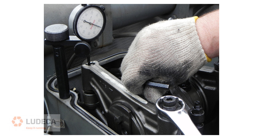
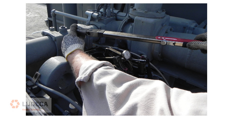
- Torque wrench – Here we are using a calibrated (hopefully) device to accurately measure how much rotational force we are inputting into a fastener. This too has some rules that must be observed to perform the job correctly.
a. No double-click: As in, bouncing off the end of the handle like it’s your own shop Pogo stick. The thought behind the double click is to ensure that the fastener is tight, and boy is it! Since the torque wrench did not return to a relaxed position, it just clicked again, but went way past the desired torque. In a case where something like 100 lb./ft. is desired, that second click made it go to perhaps 170 lb./ft. The proper way to check is to pull slowly and smoothly to the “click”, anticipating when it should happen and stopping at that point. Then, let the tool totally relax and pull again the same way. If the tool clicks with the fastener not turning anymore, then you will know it is torqued correctly.
b. The extension we mentioned earlier: A common misconception is that if you add an extension, you lose torque. While this is true with an impact wrench (because you are adding mechanical looseness), this is not the case with an extension on a torque wrench. We have a load cell that we use to prove this concept, and with about 8 feet of extensions, we asked the technician to apply 100 lb./ft. of torque. There was definitely more flex in the tool, but once all of that flex was taken up, our load cell indicated that he had put 102.3 lb./ft. of force into the sensor. So, there is no significant loss of torque from the use of extensions provided that the tool is used correctly.
c. Torque wrench storage – When I was growing up working in the family shop, my grandfather would lose his cool if he found a torque wrench put away at anything other than Zero. He would declare the tool off limits until it could be calibrated again. Unfortunately, this is another misconception about storage. Every tool manufacturer publishes what setting to set that tool to for storage, and it is normally never zero. The spring in that handle actually wants a set amount of force kept on it so it cannot drift with environmental changes like temperature or vibration. Some are specified to be set at 10% of max, or maybe at the lowest available setting, others have a set number. These specs are normally in the manual that came with the tool, but often that has been discarded or misplaced. But a few minutes on Google will surely provide the answer.
- Torque plus Turn – This picked up a lot of adherents in the 1960’s and 70’s. It is way more accurate than the torque wrench, because in a lot of cases, the torque specified was higher than some torque wrenches could register. The idea is to put a lower torque into the joint using the torque wrench, and then adding the degrees to achieve the much higher clamping force. This works great, especially if the manufacturer supplies a gauge to measure that angle. There is very little guesswork, just turn to the indicated degrees. If you need more than that, we need to get more complex equipment involved, such as hydraulics.
- Hydraulic rotation – This is for the big boys. Anyone who has had to torque something big can attest to how hard that can be with hand tools, even with a torque multiplier. Hydraulic rotation takes that task much easier, albeit more costly. This can take a large fastener, rotate it to 1000 lb./ft. or more with no trouble at all. But by the same token it is more critical to know what that force needs to be. Without much effort, it becomes very easy to over-tighten something, and that could be just as bad as under tightening. If you need more accuracy than that, then you need to apply hydraulics in a different way.
- Hydraulic Tension – this is the most accurate way to tighten a large joint. The engineers that design systems that require this know exactly how much clamping force is needed and specify the amount of force to use. In this case, a collar is threaded onto a stud and the specified pressure is applied to that collar. When it stretches the stud by the correct amount, the nut is simply run down by hand and the pressure is released. This allows the “elastic” properties of that stud to clamp the joint together. The only real issue here is the fatigue that is put into that fastener. Some manufacturers specify how many times a stud can be stretched, while others will have the tech measure the stud each time to insure it has not gone into a yield or plasticized condition.
All of these methods have their place. Anything that makes the job more accurate and more repeatable creates the opportunity for better running conditions. We haven’t yet touched on the topics of torque specs, or lubrication. These will be interesting topics for another day.
Visit our Knowledge Center for resources and tools to help you succeed when implementing and using our maintenance technologies.
Precision Maintenance: The Torque Wrench. Check Out These 15 Helpful Tips!
by Diana Pereda
Vibration Route Frequency
How often do you collect vibration data on your equipment? Is it monthly, quarterly, or even yearly? Most of the time management will allow data collection frequencies based upon the importance they assign to vibration analysis or available resources at the time. Management may ask that vibration data be collected every month or even more frequently if the machine has failed recently. Different companies and managers use different means to determine how often to collect vibration data or any other CM data for that matter.
Assigning arbitrary data collection frequencies (routes) to your equipment may do your reliability efforts a disservice. The best method is to determine the failure intervals of the failure modes (bearing defects, etc.) in the equipment. Assign data collection intervals short enough to identify these failures. For example, a bearing may develop a failure on day one and run for ninety days before it causes the machine to fail. If the machine is monitored with vibration analysis every ninety days, then your analyst may never identify the bearing failure condition in the machine. The result is that your machine will most likely fail without anyone being aware of the issue. If the same machine is monitored monthly with vibration analysis, then the bearing failure condition would most likely be identified with your vibration monitoring program. This would alert the maintenance department of the issue and allow appropriate repair efforts to be budgeted and scheduled.
Watch our Reliability Matters: What Can I Do? video to learn the benefits of vibration monitoring to keep your equipment running efficiently.
by Trent Phillips
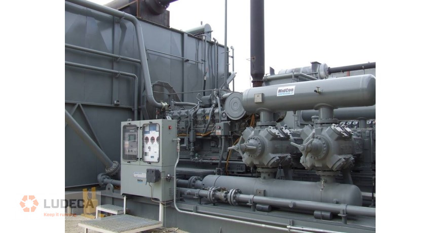
I recently spoke to a reliability engineer who was rolling out our alignment and vibration equipment to fifteen plants across the U.S. He involved us early on in the process. His company didn’t just set aside budget money for the equipment purchase, but also enough to properly train their field service personnel in how to properly use and benefit from the new technologies. We addressed not only the use of the alignment tools but also proper equipment installation, lubrication, soft foot, pipe strain, thermal growth, etc.
One of the key topics of discussion was alignment tolerances. Since this customer has high-speed ammonia compressors, this was a key concern for good alignment and they, therefore, adopted the new ANSI/ASA Standards alignment tolerances as their corporate standard. Since these tolerances are built into our laser alignment system, it was not only easy for the user to determine if the measured alignment met their established corporate alignment standards, but also for management to review the work to ensure it was correctly completed. This oversight is easily accomplished via signed PDF documentation that allows storage of the “as found” and “as left” alignment results with the work order, and also allows for easy report generation in the field for review.
I was told that their vibration analysis program still identified equipment that was out of the established alignment tolerances. How could this happen? It turned out that contractors were performing work without being held to the same standards as plant personnel, including meeting the prescribed alignment tolerances or using specific alignment equipment to perform the work. In addition, the contractor was not required to provide a copy of the results for review and digital storage.
How could this happen? Unfortunately, it is not so uncommon. Many facilities or corporations do not require that maintenance activities be performed to standards or with the equipment they can trust for the results. Additionally, they do not clearly write job plans that are issued to internal maintenance employees or contractors that specify how the acceptable results are to be achieved (what steps are required, what tools are required, what standards should be met, and what documentation of results is required.) In addition, the Maintenance Planner does not review the results of the completed work to confirm that it was satisfactorily completed within acceptable specifications. Oversight failures, as well as specification failures in job plans and work orders, can easily result in continued reliability and maintenance issues and repeated or wasted efforts to keep your equipment running.
Fortunately, the answer is not too complicated. If the problem is that the contractor is not performing the job to company standards, then the job scope and specification need to be more clearly presented in the bidding process for a job. If the requirements are clearly stated and accepted by the contractor, then they must abide by those standards. Otherwise, the contractor may risk two things: having to come back on-site to fix the issue under warranty and losing you as a customer in the long run. Communication is the key here. Being open and upfront about the expectations can avoid a lot of headaches that will linger long after the contractor has completed the job. In the case of contractors that are “permanently in-house,” the answer is a bit more complicated. A good approach to solving this issue is to involve them in training efforts within the organization. This will get them better prepared for the tasks to be done at the site. If all else fails, have a third-party expert review the work to help understand why the work was not conducted or finished properly.
by Frank Seidenthal CRL
The current business operating culture is experiencing a sea change. Some are being brought on by local and global political shifts, but more is being brought about by a worldwide pandemic and the challenges of having properly trained people available to keep equipment running as expected. Lofty goals have been promulgated in boardrooms, investor meetings, and public relations campaigns, with only marginal guidance given to operations staff to reach those goals. In some cases, these goals are received as “pie in the sky” statements and dismissed in the field as unattainable. In reality, a lot of those goals can be met and exceeded with proper work practices.
Let’s start by stating some of these goals and see what it takes to meet them without requiring a huge overhaul of operations. Upgrading tools and introducing more complete training should be part of any company’s operating plan, so we will see how much impact can be made by implementing solid information and work techniques that can impact the output of the machines, the reduction of stress of maintenance, and the achieved realization of environmental compliance.
Methane Release Reduction
Several operators in the world have a stated goal of a 10% reduction year-over-year for methane releases. These releases come from several sources, whether they are production assets or transmission lines. Very sophisticated equipment has been developed over the years to spot and record leakage, sometimes sampling the air to find the smallest PPM (Parts per Million) of hydrocarbon escaping vessels and piping. That works great when all the “Bad Actors” have been eliminated, but the truth is that most sites have the kind of leaks that overwhelm this type of sensor and make it hard to pinpoint individual sources. Maybe taking a step back and relying on tools that are less sophisticated will have a larger impact. Technology, like the SDT SonaVu, can quickly find leaks and document the source for repair and verification. Some of these leaks are large enough that the first round of audits will yield a rate of reduction much greater than 10%. The only problem for the next audit would be to come up with the same rate of success if everything is already properly repaired!

Emissions Reduction
Current emissions standards are calculated by how much CO (Carbon Monoxide), NOx (Oxides of Nitrogen), and VOC’s (Volatile Organic Compounds) are generated and released in the exhaust stream of an engine, compared to the amount of Horsepower generated by that engine. Any sort of parasitic loss within the system requires that engine work harder to accomplish the work. Reducing that loss allows for more Horsepower to be used for production or provides a buffer for the working envelope of emissions. An engine that is working above rated Horsepower is actually working outside of that envelope because the permits involved are written specifically for the advertised power, nothing over that. So how can we reduce the amount of power needed from an engine to get it back into compliance?
Stay tuned for my next blog in this series where I discuss how to reduce the amount of power needed from an engine to get it back into compliance!
by Diana Pereda
Having taken an inventory of the assets in your plant, you have identified the right tools and training that are needed to minimize unplanned work and avoid creating new defects. Even better, you’ve done some economic analysis, using conservative values, which showed less than a one-year payback and projected substantial recurring annual savings through condition monitoring (CdM) and precision maintenance (PcM).
With the strategy and economic analysis in hand, you’ve convinced your plant manager that CdM and PcM are the keys to driving reliability and profitability. The plant manager funds your equipment and training request. Over the next several months you optimize your interval-based and condition monitoring tasks, train your team members and create CdM routes and train your team on precision maintenance practices.
The CdM and PcM programs start out great. Your team identifies and resolves defects that might have gone unnoticed and perhaps catastrophically failed. The plant manager is happy, your team feels like they’re doing good work. Things are great.
Unfortunately, there is a property of all systems in nature. Systems tend to move from high states of energy to lower states of energy over time. Your CdM and PcM ‘systems’ are no different. As the energy dissipates, the only way to restore the system is to put energy into it.
Leaders have a central role in adding energy to keep systems functioning at a high level. There are three things leaders must do:
- Create a culture that will sustain the performance.
- Provide what’s needed for the team to continue to perform.
- Keep the focus on the big picture – safely delivering asset reliability that generates the best business performance.
Culture is what most people do most of the time. What people do are behaviors. Behaviors are based on long-term memories. Long-term memories are formed as short-term learning is consolidated through repetition. Training loads information into short-term memory. Practice converts short-term to long-term memories. Additional practice generates habits. When enough people have the same habits, those habits become the culture.
Leaders play a role in developing a culture in two ways. First, by providing direction, guidance, and resources. Direction includes mission, vision, values, and objectives. The guidance includes policies, plans, processes, procedures, and measures. Resources include funding, training, equipment purchases/replacements, and time for people to achieve and maintain habits.
Second, leaders develop and reinforce culture by applying productive leadership. Leaders should want to be leaders and want to be accountable. They need to learn and apply leadership roles, leadership attributes, and leadership skills. They should understand and properly apply sources of position and personal power. Leaders must also understand how to influence others based on needs and motivations. And leaders should set motivating goals. More information on these leadership elements can be found in my book, The Productive Leadership System.

Providing what’s needed for the team to perform means making sure your team has what they need to continue carrying out your direction and guidance. Turnover happens. People retire, get promoted, move to other positions, etc. Make sure there is good support in place to train new people and upgrade the skills of current technicians. Leaders have a role in this by planning, budgeting, and defending expenditures for training, replacing/upgrading tools, calibrating sensors, and upgrading software and firmware.
Leaders have a role in keeping the focus on the big picture by identifying and communicating matters related to the CdM and PcM programs. There can be counter-productive matters like operations not allowing time for rotating equipment to be precision aligned or balanced, or not heeding a warning that a bearing is about to fail. Communicate when positive things have occurred; a 50% increase in critical motor mean time between failure, 15% reduction in unplanned work orders, and 5% reduced maintenance costs as a percentage of the total cost.
Thank you Tom Moriarty with Alidade MER, Inc. for sharing this excellent and informative piece with us!
by Diana Pereda
In recent years, “Defect Elimination” has become a hot topic in the reliability world. But what exactly does defect elimination mean? How does it differ from other maintenance practices? Is it more than just a new way to describe planned and predictive maintenance?

Let me start by answering a more basic question. What is a defect? According to Merriam Webster’s online dictionary, a defect is defined as “an imperfection that impairs worth or utility”. The simple definition of a defect that we have used for the past 25 years in The Manufacturing Game® workshops is “Anything that erodes value, reduces production, compromises health, safety or environmental performance or creates waste”. Or in the words of the fictional Chance Brooks, plant manager turned corporate manager in the book Don’t Just Fix It, Improve It “…I came to regard defects as my real enemy. I always thought of them as the little imperfections that caused all of our problems and upsets. Some were big and some small, but when they lined up in just the right way… kaboom!!! A catastrophe would hit.”
A lot of time and attention has been paid to breaking the reactive maintenance cycle – equipment fails, operations call maintenance, maintenance repairs the equipment and turns it back over to operations – rinse and repeat.
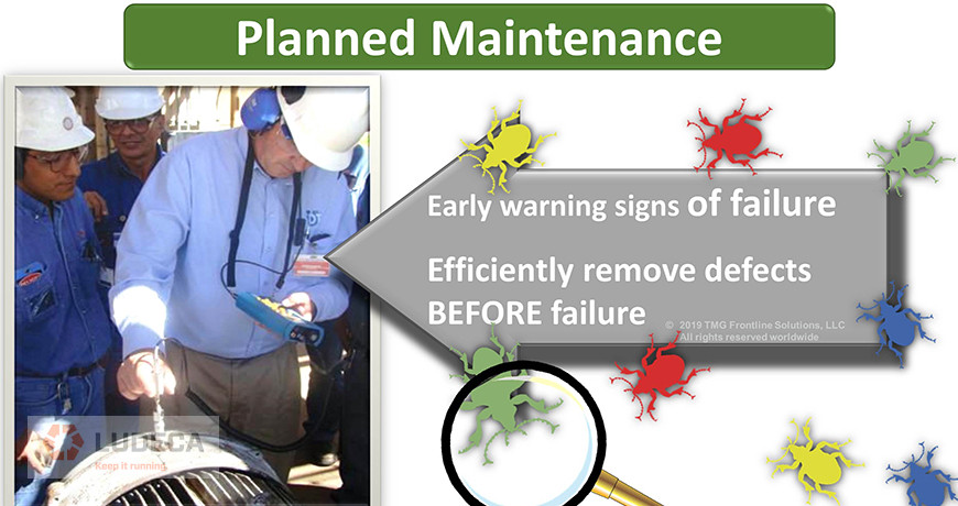
Many organizations now perform time-based preventive maintenance, use predictive technologies, and perform operator rounds, all to find defects when they are. Then effective planning (the what, why, and how of the job) and scheduling (the when and by whom of the job) are employed to remove those defects prior to the functional failure or perish the thought, catastrophic failure of the equipment. Those are all characteristics of planned maintenance – simply put, finding defects and efficiently removing them before they cause a failure. A much more efficient and cost-effective approach than fixing broken stuff!
But what can be done to prevent defects from getting into the equipment in the first place? Like death and taxes, having some defects is a certainty – normal wear and tear happens. But most organizations have far more defects than can be ascribed to normal wear and tear. There’s no doubt that “extra” defects sneak in based on how we operate and maintain the equipment. It’s these defects that are not inevitable. And if we prevent them from ever getting into the equipment, we can avoid all of that work required to detect and remove them.
Misalignment is one of those “extra” defects that can be avoided through proper repair and installation techniques, both of which are made significantly easier and more effective with the use of laser alignment tools. Properly aligned equipment has less machine vibration, fewer bearing and coupling failures, and may even consume less energy.

But the opportunities don’t stop there. Tools that have historically been used in support of planned maintenance to find defects that are hidden from the human senses can also be used in a defect elimination capacity to avoid putting defects into the equipment in the first place. For example, ultrasound solutions can be used to provide insight into the current health of an asset in a planned maintenance capacity, but they can also be used in a defect elimination capacity to ensure that the proper amount of lubrication is administered, avoiding the introduction of over or under lubrication defects.
To achieve truly breakthrough performance, an organization has to do more than improve their work efficiency through Planned Maintenance. They must find ways to make some of the work go away. That is where harnessing the power of site‑wide Defect Elimination and available technologies can provide true leverage. To achieve sustainable reliability improvements, the frontline workforce can make or break you. So don’t just tell them about it, don’t just show them; instead, give everyone in the organization a role to play in the process so that they can truly understand and contribute. That brings true buy-in and with it a fighting chance at sustainability. Go beyond Planned Maintenance. Don’t Just Fix It, Improve It!
Thank you Michelle Ledet Henley with The Manufacturing Game for sharing this informative article on defect elimination with us!
by Diana Pereda
The following tips are ideas to consider for when “the going gets tough”, meaning that problems like residual soft foot, “bad geometry”, or becoming bolt-bound impede your ability to easily obtain an excellent alignment. But first, a few definitions:
- Residual soft foot: More soft foot than you are comfortable with, but can’t do anything about. Can be caused by problems like slightly angled feet or a bit of pipe strain.
- Bad geometry: Equipment where the distance from the coupling center to the front feet is equal to or greater than the distance from the front feet to the back feet.
- Becoming bolt-bound or base-bound: When alignment corrections can’t be made because you have run out of room in the anchor bolt holes in the feet, or have to come down but have no shims left under the feet to remove.
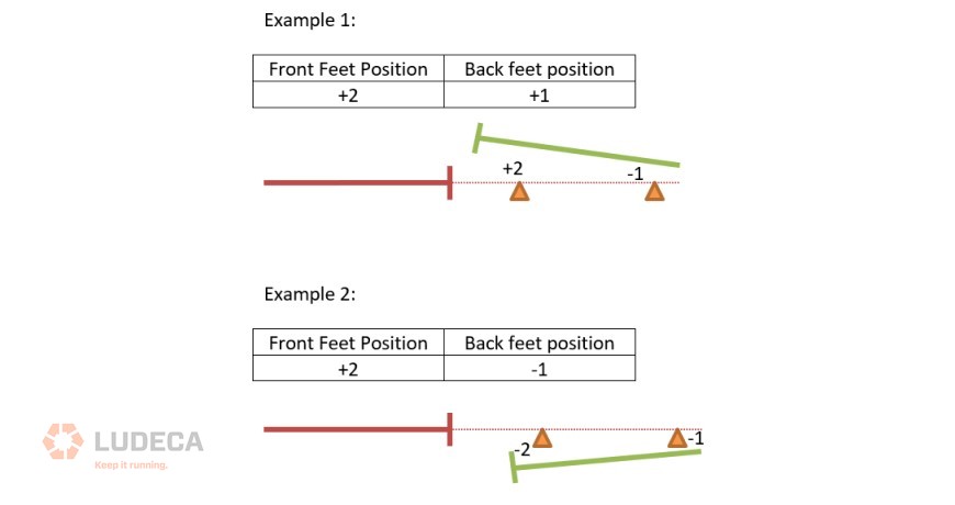
Final Vertical Misalignment Correction (Horizontal Misalignment already close)
1. Position front feet close to offset tolerance. Finish the alignment by moving the rear feet only.
2. Final foot positioning should make offset at the coupling center decrease. To achieve this, position feet as shown in the below example:
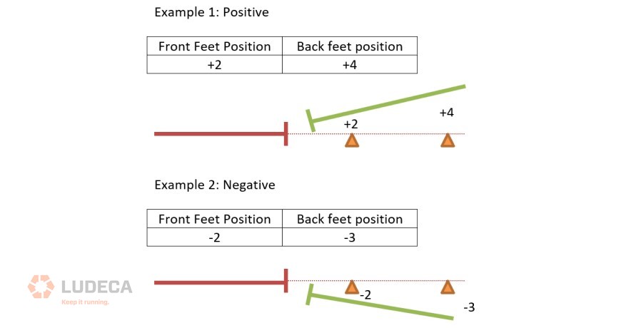
3. One must avoid leaving feet positioned with opposite signs, even if the values are very small. Below is an example:
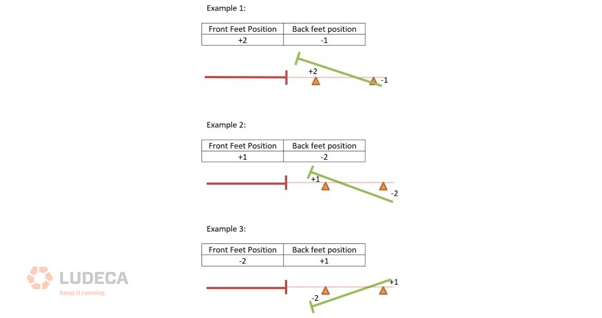
4. One must also avoid allowing the position value of the front feet to be higher than the back feet value, even if they have the same sign. Shown below.
Notes:
- The above rules apply to horizontal corrections as well.
- Remember to torque the anchor bolts on small equipment in steps.
Watch our Shaft Alignment Know-How: What’s Misalignment video to learn the causes and effects of having misalignment in your rotating equipment.
by Diana Pereda
I’m a potential failure! I am the result of improper equipment design, procurement, installation, maintenance, and operation. I exist under extreme conditions for which I was never designed. I haven’t hidden or been silent, but most have ignored me and all have allowed me to grow. I’ll become a risk of severe damage and injury.
One day I will reach my full potential and show everyone what a failure I have become. At that moment, everyone will wish I had been given the early attention and mitigation I deserved.
Don’t feel sorry for me, because I am not alone, and will most likely return. I have created many other potential failures like myself. Some of those failures will cause even more harm and damage. Most likely, I will be reborn on the same equipment again and again due to improper maintenance practices.
If this does not concern you, then do nothing and let me show you what an equipment failure can really cost you when you least expect it and didn’t prepare for it. If you don’t like having me around, then what can you do? Here are some activities your maintenance and engineering departments can perform to prevent me from happening and ensure your equipment is operational upon demand, meaning reliable:
- Design for reliability
- Design for maintainability
- Design for operability
- Manage maintenance backlog
- Plan work, then schedule it and finally ensure it is properly executed
- Focus on PdM activities like vibration monitoring, IR thermography, lubrication analysis, and many more as a routine exercise
- Ensure precision maintenance is routinely done
- Perform operator checks
- Maintain properly written and continually optimized preventative maintenance activities that return value
- Provide training for operators, mechanics, and engineers to help ensure precision maintenance, proper operation, and reliable design
- Perform root cause analysis
- Ensure failure modes and effects analysis is a routine part of your maintenance and reliability efforts
- Ensure that you have identified all critical assets
- Ensure you have mitigation plans in place to deal with critical equipment failures
- Ensure that critical spare parts are available, properly stored, and easily accessible when needed
Visit our Knowledge Center for resources and tools to help you succeed when implementing and using our maintenance technologies! Watch our video tutorials, download infographics, plus explore other helpful information to reduce equipment failures and downtime.
by Diana Pereda