When using short-flex coupling tolerances, the centerline of rotation of each machine is aligned at the coupling center, which is the center between the flex planes, or the average center of power of transmission points. Using simple geometry, it’s easy to see why short-flex coupling tolerances are too tight when using spacer couplings. In this example, the only variable is the axial length of the coupling. A small short-flex coupling is compared to a long spacer coupling, but the machine used and feet corrections remain the same. This makes it easy to see how the length of the coupling affects the movement of the centerline of rotation at the coupling center.
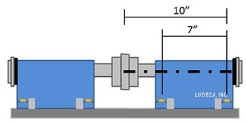
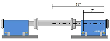
The dimensions required for this example are shown in the figures below. In Figure 1, the front and back feet of the machine are 7″ apart. The distance from the back feet to the centerline of rotation at the coupling center of the short flex coupling is 10″. In Figure 2, the latter dimension, which is 18″, represents the distance from the back feet to the center of a 16″ spacer coupling. Note that this coupling center extends 8″ (half of the spacer coupling length) past the first flex plane or first point of power transmission.
In the next step, a 2-mil shim is added to the front feet of the right machine, and the back feet are left untouched. This correction is arbitrary and can be represented using three equivalent triangles as shown below.
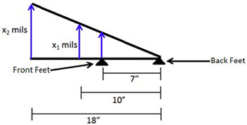
The total movement of the centerline of rotation at the center of each coupling type is represented by x1 for the short coupling (Figure 1) and x2 for the spacer coupling (Figure 2). These values can be found by setting the ratios of each triangle’s legs equal to each other.
(1 “mil” )/(7 “inches” )=(x_1 “mils” )/(10 “inches” )=(x_2 “mils” )/(18 “inches” )
The figure below shows the total movements at the coupling centers.
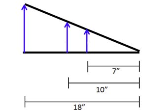
After adding 2 mils to the front feet of the machine, the centerline of rotation moved 2.9 mils at the short-flex coupling center and 5.1 mils at the middle of the spacer coupling. That’s a 76% larger movement at the spacer coupling center! This goes to show that the further away the coupling center is from the moveable machine’s feet, the more sensitive the movement will be. It may take all day to align the machine with a spacer coupling to short-coupling tolerances because a small movement at the feet turns into a large movement at the coupling center. The machine may even be aligned within an appropriate spacer shaft tolerance, but the tool will still show that there is misalignment if short-flex coupling tolerances are selected. As a rule of thumb, if the coupling length is smaller than 4″ between flex planes, use short-flex tolerances. If this distance is greater than 4″, use spacer shaft tolerances and make your life easier.

Filed under:
Alignment by Silvio Attanasio CRL