When moving machines for alignment, always use jackscrews. If you don’t have them, beating on the machine frame with a steel-face hammer is a lousy idea.
First, you run the risk of damaging the bearings, seals, and other delicate components in your machines. Secondly, you have little control over the magnitude of your moves. Thirdly, it’s unprofessional. If you don’t have time to weld or screw-on jackscrew assemblies, consider using a couple of carpenter’s pipe clamps, tensed against each other. This makes for a handy portable jackscrew arrangement that is safe, inexpensive, and offers you plenty of control. If this is not possible either, and you must hit the machine with a hammer, then at least do so with a plastic-face, shot-loaded dead-blow hammer.
by Ana Maria Delgado, CRL
A customer in Florida needed to do an alignment between a gas turbine and a generator. Their main issue was that the gas turbine shaft could not be rotated by hand and engineering was reluctant at that time to turn on the lift oil pumps. This customer owns and uses the ROTALIGN® ULTRA iS. We suggested using the Multipoint measurement mode in the ROTALIGN ULTRA iS in conjunction with one ALI 2.230 Magnetic Sliding Bracket for the turbine shaft and one ALI 2.112set Compact Magnetic Bracket. With the shafts uncoupled, the generator shaft could be rotated to any position, and the sensor could be positioned at any rotational position on the turbine shaft with the magnetic sliding bracket. A very big advantage of using the ROTALIGN ULTRA iS in the Multipoint mode is that thanks to the quality factor value obtained from the readings a very clear picture emerges of the quality of the data obtained while taking the readings. Any rogue measurements caused by surface imperfections in the turbine coupling can be eliminated without compromising otherwise good data. The ROTALIGN ULTRA’s Technical Note # 12 – for Non-Rotating Shafts was provided to the customer to better guide the process.
Accurate readings were obtained quickly and efficiently, resulting in many man-hours saved on this critical alignment job.
by Alan Luedeking CRL CMRP
Recently, while visiting the West Coast, I had an opportunity to get involved in an alignment with Mr. Roy Loop from The Rueck Company on a tug boat being built on the Columbia River near Portland, OR. This tug will be put into service halfway around the world where it will be towing and docking ships into and out of ports. A failure in this remote location would make repairs extremely expensive for the owner, not only due to its service location but because of lost revenue from the vessel being out of service.

Knowing this, the tug boat’s owner wanted to verify the alignment of the drive lines (both port & starboard) to ensure they were within the required alignment tolerances before putting the vessel into service.
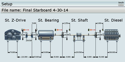
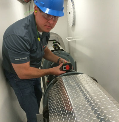
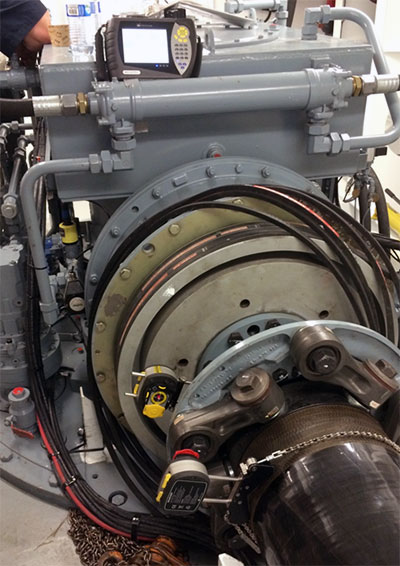
The interesting about this application is that the driveshaft goes through a bulkhead so there is no line of sight between the Z-drive and the diesel engine. In the image below you can see the bulkhead. The diesel engine is on the other side of this bulkhead. In this picture, we are setting up the receiver on a 17-foot jackshaft.
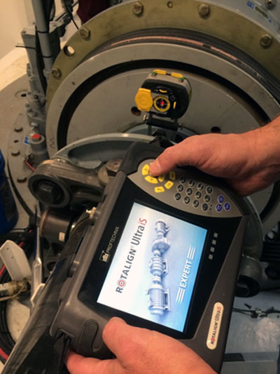
Fortunately, we had a ROTALIGN ULTRA iS Laser System (with Expert level firmware). This firmware gave us the capability to set up multiple laser heads on all of the drive train components and thereby measure the entire machine train with just one rotation. Despite the fact that two sets of lasers and receivers were on the other side of the bulkhead, we could still establish communication via the powerful Bluetooth module built into the laser equipment. The ROTALIGN ULTRA iS is the only system on the market that is capable of performing this alignment measurement across multiple couplings simultaneously with just one rotation of the driveline. In order to rotate the shafts, the drive train typically needs to be cranked by hand using a ratchet on the diesel’s flywheel. This is extremely tiring, time-consuming, and difficult to do. If you had to “crank” the diesel for each of the four couplings one at a time, the job might take several hours just to take the readings. With this alignment set-up, we were able to use the ROTALIGN’s unique Continuous Sweep measurement mode, so there was no need to stop and start at any specific measurement location.
Three sets of readings were taken to verify repeatability using the ROTALIGN’s unique measurement table. This measurement table allowed us to view each of the coupling’s three readings in a table to verify repeatability and (if desired) average these readings together. Each set of readings was accomplished with just a single turn of the shafts with less than 100 degrees rotation. The entire alignment data collection process (all three sets of readings) was accomplished in just a few minutes.
When making live moves/corrections, the ROTALIGN ULTRA iS Expert allowed us to see the alignment condition at each coupling simultaneously in real-time for both the Vertical and Horizontal directions. This is another unique capability that is extremely important, since, when one component of the drive train is moved, it affects the alignment condition at the other couplings. Having this capability is a huge time saver, reducing the job sometimes from days to just hours.
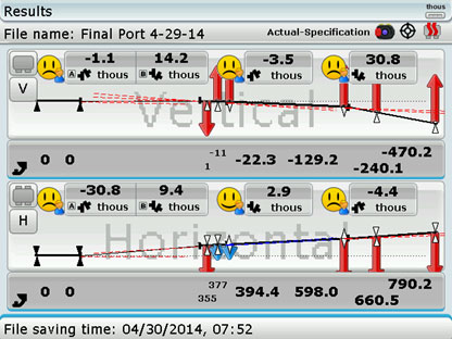
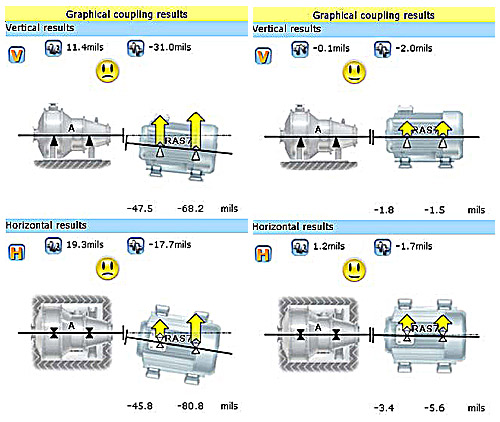
AS FOUND results:
As LEFT results:

The alignment tolerances from the coupling manufacturer were given in degrees of angularity rather than as gap differences at the coupling. To verify that the alignment was within the coupling manufacturer’s tolerances, the Rotalign Ultra allowed us to instantly convert the measured alignment condition to display the angle in degrees rather than as a gap. Below is the final reading in degrees:
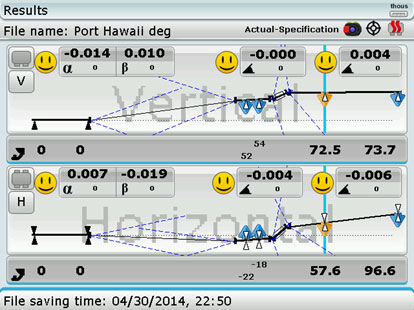
The alignment was accomplished within alignment specifications, as shown by the smiley faces. The ship’s owner was confident that alignment would not be an issue and gave the green light to put the tug into service.
by Frank Seidenthal CRL
Some weeks ago, a compressor manufacturer contracted us to perform ROTALIGN® ULTRA laser alignment training at their testing facility. During the training, the millwrights mentioned that they had a need to align the gearbox shaft to the compressor bores during the assembly process before the compressor shaft was installed. Since my ROTALIGN ULTRA also features the CENTRALIGN® ULTRA bore alignment option, I offered to train them on this interesting application.
The objective was to perform the alignment so that when the compressor shaft is put in, it is already within tolerance and the compressor is immediately ready to be tested. This means that the millwrights need to align the static centerline of the bores of the compressor to the rotating centerline of the gearbox shaft. This is a challenging application that the ROTALIGN ULTRA with CENTRALIGN ULTRA can handle with ease (see Figure 1.)
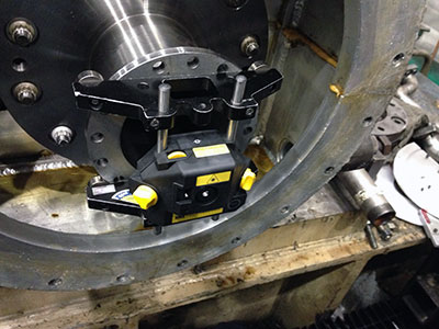
Fig. 1: Laser mounted on Rotating Gearbox Shaft
We first covered the key concepts of what it means to do a bore alignment. Hands-on exercises illustrated the differences between aligning with a static laser beam through the bores and a rotating laser setup on the gearbox shaft. Once on the shop floor, we were able to measure a compressor’s bores with respect to the gearbox shaft within 45 minutes, start to finish including setup time for both stages of the measurement (see Figure 2.)

Fig. 2: Receiver with Bluetooth module in compressor bore
The millwrights seemed thrilled with the simplicity of the process, compared to their current approach, which involved using a complicated bracket system to support dial indicators, sometimes taking up to a day to obtain accurate measurements.
The customer purchased the ROTALIGN ULTRA with CENTRALIGN ULTRA option and now obtains accurate and repeatable measurements within an hour, without depending on the skill level of the operator. This has freed up manpower, save time, and a great deal of money during the compressor assembly process.
by Adam Stredel CRL
“Thermal growth” often refers to the change in machinery positions as a machine runs from startup to operating conditions (or vice versa). Machinery positional change can also be caused by dynamic forces, pipe stress and other factors. Compensating for thermal growth is necessary because the machine will be misaligned during operating conditions if it is not. —Daus Studenberg, Applications Engineer – LUDECA, Inc.
 Thermal Growth and Machinery Movement Crash Course Video
Machinery movement and thermal growth are two of the main issues that affect operation and life of machinery. Watch our crash course video and see how continuous monitoring of positional change can eliminate checks and calculations and provide an exact solution.
by Ana Maria Delgado, CRL
If you have a vertical flange-mounted motor and need to shim it to correct angularity, our laser systems provide the following handy options to accomplish this:
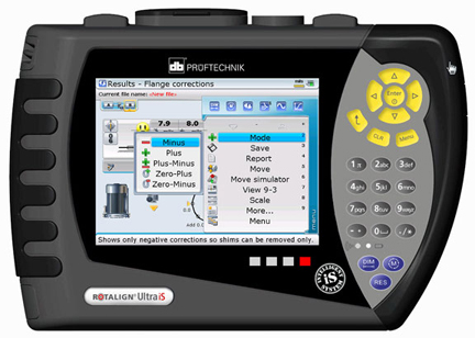
How to decide which option to use?
MINUS: If you have plenty of shims already there, you can select this option to minimize the number of shims used, since the correction will be accomplished by removing (subtracting) shims.
PLUS: if you have no shims between the motor flange and support flange, to begin with, you can select this option to affect the correction by only adding shims.
PLUS-MINUS: With this option, exactly half of your corrections will be positive (adding shims) and half will be negative (removing shims). This option is very handy if your pump impeller hangs from the thrust bearing in the motor and you do not want to change the pump shaft’s axial position. The plus-minus option makes your pivot point the shaft centerline itself so that the correction will have no z-axis effect on the shaft from shimming at all. This also minimizes the absolute amount of shimming needed.
ZERO-PLUS: This option means all positive shimming but forces one bolt location to be zero (no correction). This is very handy when the bolt circle diameter is the same as the flange diameter, or you already have some shims between the flanges to start with and want to minimize the amount of shimming needed.
ZERO-MINUS: This solution is similar to ZERO-PLUS but in the negative direction, meaning all corrections call for removing shims, with one bolt position at zero correction. This is handy if you have lots of shims already between the flanges and want to reduce these while minimizing the corrections needed.
by Carlos Bienes CRL
Proper location is very important when collecting vibration measurements on a belt system. If possible, one reading should be taken in line with the sheaves and one reading perpendicular to them on each bearing. Vibration data resolution should be taken into account so that proper separation between belt and driver frequencies can be obtained. Care should be taken to ensure proper belt alignment as well. A laser pulley alignment tool provides the most efficient means to properly align belts. Another issue is how the belts are installed. Was the equipment loosened and the belt put on properly? Were the belts instead rolled on by force, creating potential issues? Have you ever seen a Vee belt running upside down? This is usually caused by the cording in the back of the belt being broken often caused by rolling on the belts. Are sheave gauges being used to check the sheaves for wear? In some cases, the cost of a belt is more than the cost of a new sheave. These are just some of the things to consider for proper installation, maintenance, and identification of belt-related problems.
Don’t just assume that belts are simple and do not require best practice actions for proper operation.
by Gary James CRL
Recently our customer, Metropolitan Sewer District of Greater Cincinnati (MSD), shared with us their successful findings with OPTALIGN SMART. Their Maintenance Department utilizes a variety of predictive technologies and preventive strategies to support their mission of improving equipment reliability and reducing downtime.
They are committed to extending the life cycles of their assets with their already established laser alignment program.
Their recent analysis started when their Maintenance Crew Leader downloaded and interpreted the alignment test results. Planned scheduled follow-up work orders, baseline testing, realignment, and retesting revealed that one of their pumps showed excessive shaft misalignment between the pump and motor in both the horizontal and vertical planes. As-found test results showed the equipment out of vertical alignment by 11.4 thousandths, and horizontal alignment off by 19.3 thousandths. The maintenance staff proceeded to generate a follow-up work order to realign the pump and motor.
Follow-up Actions:
Plant Maintenance Workers uncoupled and realigned the components, using jacking lugs and shims to correct the misalignment. After realignment work was completed, they installed a new coupling and performed follow-up retesting with the OPTALIGN SMART tool, verifying that the components had been aligned within the required specifications.
They have now proven that equipment misalignment will cause mechanical seal failure and premature bearing wear, resulting in equipment failure and unexpected downtime. By testing and aligning equipment proactively, MSD Maintenance personnel were able to identify and correct misalignment problems before irreversible damage occurred and assets would have had to be replaced. The total work order cost for testing and realigning this asset was $154.70. The purchase price of a new pump of this type is $2,456.00, resulting in a minimum cost avoidance of $2,301.30, not including labor costs to remove and reinstall the equipment.
Special thanks to our friends at Metropolitan Sewer District of Greater Cincinnati for sharing their success with us and reminding us once again that there are just No Excuses for Misalignment.
by Yolanda Lopez
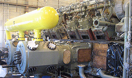 The bore alignment of the crosshead guides in a large compressor driven by a 4, 000 HP engine was thought to be a problem after this compressor, which had run trouble-free for 30 years started having problems. Methods used before involved checking with a machinist’s level only. The crosshead guides have an approximate diameter of 20”.
The ROTALIGN® ULTRA laser shaft alignment system with CENTRALIGN® ULTRA bore alignment add-on module was brought in and five cylinders were checked. Each cylinder to crosshead guide measurement took about 1 hour to complete, including setup and measurement. Most fell within five-thousandths of an inch of offset. One cylinder and crosshead guide were found to be out of alignment. This cylinder was measured to be lower than the crosshead guide by 70 thousandths and 65 thousandths at the inboard and outboard ends respectively. This result could not have been measured with the machinist’s level. Also, with the level no ability to check side-to-side misalignment exists.
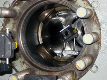
Some wear was detected, so we were able to avoid the “bad” spots with the CENTRALIGN pointer bracket.
Repeatability was typical, at under 0.5 thousandths. The low Standard Deviation (SD) values provided by the ROTALIGN confirmed that measurements were not hitting damaged sections and were highly reliable. SD is not available with tight wire measurements, which can lead to having incorrect center readings. In addition, obstructions and confined spaces make tight wire setup and readings extremely difficult.
The ROTALIGN ULTRA with CENTRALIGN helped reveal problems with 100% confidence in measurements and with excellent repeatability, in a fraction of the time that would otherwise have been required using other, less accurate and less reliable methods. This resulted in great savings for the customer.
by Daus Studenberg CRL
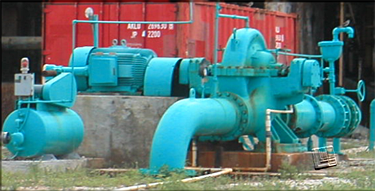
The customer needed to align a boiler feed pump to a fluid drive.
Before doing so, we took care of the simple but often-ignored pre-alignment checks, including a thorough cleaning up of the area around the machines. The area was a mess to start with, and cleaning up allowed us to check for soft foot and start making moves immediately after taking readings, without delays.

Some of the essential clean-up and preparation tasks we performed were:
- Clean up the work area.
- Remove jacking bolt fixtures and wire brush the corrosion off them.
- Cleaning and greasing the hold-down bolts and jack bolts with white lithium grease.
- Drilled and tapped new holes in the base to add jack bolts where there weren’t any.
- Replaced dirty used shims with new precut stainless steel shims.
- Rough aligned the pump so its anchor bolts were centered in bolt holes of the feet.
This preparation work saved much time on the actual alignment, and more importantly, ensures that the next time this job must be performed the jackscrews, base, and anchor bolts will be in good condition, allowing the machines to be quickly and accurately realigned.
by Carlos Bienes CRL
When M/Y Mystique, a 50m yacht, had trouble with its bearings overheating, they called on our customer AME to investigate. After conducting a vibration analysis survey, the misalignment was discovered along with aged mounts. Additionally, the Kamewa Jet Units were not functioning within recommended tolerances.
In terms of alignment several steps were followed, the first intermediate shafts of both wing engines were re-connected. The alignment of these shafts was checked using the Rotalign Ultra and found to be within alignment tolerances. There is only one intermediate shaft for the center engine and only one SKF bearing that supports the jet shaft. The cap of this bearing was torqued to 600 ft./lbs. according to spec. Two cradles were installed under this shaft so it could be aligned to the jet shaft. Wing engines were also aligned to their corresponding reduction gears. Finally, the center engine and reduction gears were aligned to their corresponding intermediate shafts.
AME installed all new mounts and aligned the propulsion equipment to correct the vessel’s issues using the ROTALIGN ULTRA laser alignment system. Upon completion of the work, it was concluded that the replacement of all propulsion machinery mount elements and the re-alignment of this machinery greatly reduced engine vibration being transmitted to the base structure. Most of all, the temperatures of all SKF shaft bearings were improved and found to be within their temperature tolerances.
“Once I found out that AME had a history with Mystique and its previous owner, it was a no-brainer to get them involved to do this specialized work,” said S.P. Captain, M/Y Mystique. “AME has a reputation of being one of the top specialists in vibration, noise, and alignment and I will continue to use their services due to the prompt, professional engineers, and staff. They care about their clients and will do whatever it takes to deliver impeccable service.”
Thanks to Advanced Mechanical Enterprises for sharing their success using our ROTALIGN ULTRA.
by Ana Maria Delgado, CRL
Recently, our customer AME was commissioned by Harry Pepper to perform laser alignment with the ROTALIGN ULTRA on 4 Caterpillar Diesel Engines to Philadelphia gear at their Merritt Pump Station in Naples, Florida.
“We had AME laser align our engines because we’ve used them on previous projects with excellent results,” said D.W., Project Superintendent, Harry Pepper. “We will continue using them for pump stations and water treatment plants. These services increase efficiency by saving time over regular millwright procedures and the third party aspect carries considerable weight with inspectors and owners.”
The pumps have a capacity of 100,000 gallons per minute – proper alignment will help the pumps run more efficiently and reduce the likelihood of unexpected downtime – a smart decision for any maintenance program.
Thanks to Advanced Mechanical Enterprises for sharing some of their industrial news with us.
by Ana Maria Delgado, CRL
I am often asked, What tools and equipment do a millwright team need to do shaft alignment? Beyond the obvious safety equipment, such as hearing protection, steel-toe shoes, work gloves, hard hat, safety glasses, and fire retardant clothing, some of the other essential equipment is not so obvious. So here’s a little list, with commentary, based on nearly 30 years of field experience:
- Laser Shaft Alignment System
- Precut Stainless Steel Shims
- Shears, Flat File, and Ball-Peen Hammer
- Pancake Jacks and Pry Bars
- Inside and Outside Micrometers
- Set of Feeler Gauges
- Torque Wrench with Crow’s Foot Adapter
- Dead Blow Hammer
- Flashlight
- Pi Tape
- White Correction Fluid and Scribe
- Cotton Rags
- Dry Spray Solvent and a Can of Compressed Air
- 50-Foot Extension Cord with Triple Tap
- Sturdy Folding Work Table and Chair
Download my entire UPTIME MAGAZINE article Equipping a Field Service Team to do Shaft Alignment
by Alan Luedeking CRL CMRP
The accurate shaft alignment of an automotive transmission testing robot presented great difficulty in obtaining the alignment measurements. A system was needed that could align the shafts of various machines simultaneously across larger distances. The main difficulty was an uncoupled measurement for two precision spindles about 5 feet across.
The ROTALIGN® ULTRA iS with the IntelliPass measure mode capability solved these problems. You didn’t have to be careful using it, and it was effortless and easy to use. The results were about 0.2-0.3 thousandths repeatability in offset measurements, with large time savings in collecting the data.
by Daus Studenberg CRL
LUDECAwind was recently hired to perform an alignment on a wind turbine. Although the turbine was quite modern in size, capability, and throughput, its design and functionality for wind service technicians to perform their tasks are outdated. The technicians are barely able to stand straight or get around the turbine without compromising their safety.
With the obstacles of working inside the nacelle, the difficulty of aligning the wind turbine seems even greater considering the procedures which need to be followed and the number of components that need to be removed for accessibility to perform this task. There was a misconception that in order to perform any type of alignment, the coupling needed to be removed. The beauty of using our OPTALIGN® SMART RS laser alignment wind system is that the technician is not required to remove the coupling to execute the task. No matter the size of the turbine, type of coupling, or interference around the working area, using a laser alignment system inside a nacelle not only saves time but provides true, accurate, and repeatable data.

We were able to mount the OPTALIGN SMART RS wind system, collect repeatable and accurate data, and make all necessary corrections in a short amount of time. The customer was impressed with the system’s ease of use and the accuracy obtained, considering the less than ideal conditions with high winds of approximately 13 m/s, which had no effect on the quality of the data collected.
by Alex Nino CRL
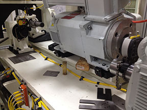
A few weeks ago, I was doing training at an engine overhaul shop in the Midwest. They had just purchased a CENTRALIGN® ULTRA STANDARD system to perform bore alignment checks, before reassembly of each engine (see Figure 1.) After showing the mechanics how to set up the laser and take measurements on the first bore (the one furthest from the laser, as recommended), they were eager to take over and measure the bores themselves.
Before purchasing the CENTRALIGN system, they were using piano wire as their alignment tool. Now it’s a much faster and more reliable process with our laser system.
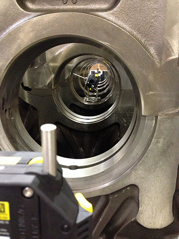
We shot the laser beam roughly through the center of all bores to create a point of reference for each bore. Next, we measured each of the bores to obtain the position of each bore with respect to the laser line. With the ability to take as many points per bore as we did, we were also able to tell if each bore was out of round. We took at least eight points along the surface of each bore, and then re-measured the entire engine to establish repeatability. The mechanics were amazed at how easy it was to measure with a laser, in comparison to the painstaking and difficult piano wire method.
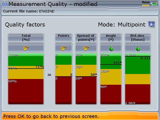
After measuring each bore, I showed them how to look at the quality factor (see Figure 2.) Seeing that they could improve their quality by taking more points, they were able to improve their measurement process. By the time they were on the last bore (the one nearest the laser emitter), the quality of their readings was near 100%. Finally, the bores at each end were fixed in the firmware to establish a reference line for the rest of the bores.
The centerline position of each bore in the engine could now be established with respect to this line (see Figure 3.)
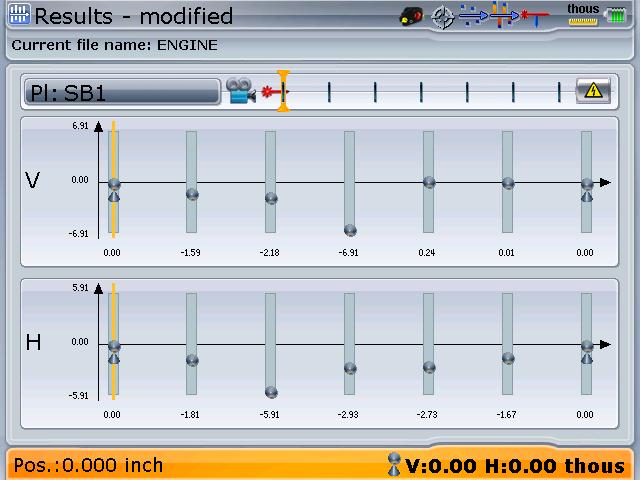
Another interesting feature of the Centralign is that the bore alignment can be optimized to a centerline that minimizes the misalignment of the entire bore train, rather than arbitrarily establishing a reference line through any two of them. Another feature allows one to see a differential view of the alignment, which establishes the misalignment of any individual bore to a reference line formed by its two adjacent neighbors. This often saves unnecessary correction or milling work if it can be seen that the misalignment of any one bore is not too great with respect to its nearest neighbors—a very handy feature.
The mechanics were happy with the results obtained as these matched the readings they had taken with the piano wire. At the end of the training, one gentleman exclaimed, “I won’t ever use piano wire again!”
by Adam Stredel CRL
While aligning a Flowserve Booster Pump in Arkansas, the attempted alignment corrections proved unrepeatable and inconsistent. The centerline of the pump shifted from too high to too low and from too far to the right to too far left. I thought this might be a symptom of pipe stress and suggested to the customer that I check for it. Upon loosening the hold-down bolts, I noticed that piping lifted the pump right off the base.
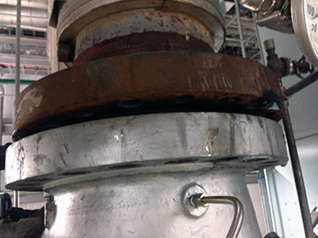
I was authorized to disconnect the piping from the pump. Figure 1 shows that at its worst one pipe was one inch out horizontally and about one and a half inches vertically, and angled to the pump.
We aligned the pump without the pipes connected. The customer was advised to redesign the pipe hangers to provide more support to the piping and reduce the stress on the pump.
It is imperative that once the pipefitting is complete and the piping is reattached to the pump, the alignment and pipe stress measurement with the laser will have to be checked once more.
by Carlos Bienes CRL
I recently visited a power plant in the Caribbean to perform vibration analysis services. As I discussed the agenda with my point of contact, I asked for a walk-through of his facility. I was a bit surprised to see the amount of rotating equipment present in such a small area. But in particular, I was surprised to hear a lot of loud noise coming from several different auxiliary machines. Even though I had my PPE gear on, I still heard a very large pitching-type noise.
As I found that noise rather high and annoying, I asked my point of contact about the particulars of this motor pump assembly. The pump has been in service for quite a while and they recently replaced the bearings and couplings.
I asked what type of method they were using to align their equipment and the answer was straight edge and dial indicator, but that the coupling and pump bearings were new.
I took the opportunity to get my VIBXPERT® II vibration analyzer out and collect data on that particular machine first. To no surprise, the data showed severe misalignment across the coupling. I reconfirmed the data using phase analysis. I noticed while doing this that the pump was hot. After viewing the data on the analyzer I asked the customer if they had thermal growth specifications for that machine. He was unaware of them having any such data for the pump. I advised him that there are systems out there that could not only perform the alignment but could also measure the amount of dynamic movement that occurs on a machine, a true cold to hot or hot to cold measurement.
The following day the customer was able to bring the machine down for a few minutes and we mounted a ROTALIGN® ULTRA IS laser alignment system and took alignment readings. Within seconds we confirmed that machines were severely misaligned, as had been indicated by the VIBXPERT. Next, we installed LiveTrend brackets and ran the machine for approximately 45 minutes, and as expected they showed a rather large positional change as they ramped up. The customer was not only able to see the misalignment using vibration technology but also found a solution to his reliability problems. The overstocking of couplings and bearings could now be reduced with the true and accurate data obtained from the laser alignment system and vibration data collector and analyzer.
by Alex Nino CRL
By Deron Jozokos with Shoreline Reliability, LUDECA solutions provider for New England and Eastern New York
I recently helped a customer with an alignment issue they were having on a pump-gearbox-motor machine train. The problem was that although the machines were aligned within spec, after a short period of runtime the 16, 500 HP motor shaft began shuttling in and out, or “hunting” for the magnetic center, creating a fear that the coupling would break under the tremendous forces acting on it. This would in turn shut down the nuclear plant, costing millions of dollars in lost production. One theory was that the rotor was not level causing it to slide downhill while magnetic forces were drawing it back uphill. With just a short window of time, the site engineers wanted to level the motor shaft without losing the excellent alignment tolerances.
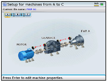
To save time, we measured both machine train couplings simultaneously using the ROTALIGN® ULTRA’s multi-coupling expert level feature. We then used the INCLINEO® system to measure the angle of the motor shaft with respect to gravity. We verified that the train alignment was still within excellent tolerances (See the ‘As-Found’ condition below) and measured a motor shaft angle of 0.489mils/inch.
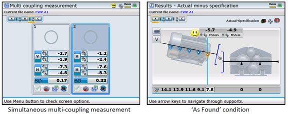
Since a hydraulic torque wrench was needed to loosen the 10 total bolts, it was imperative that the number of alignment corrections be reduced to the fewest possible, preferably just one. Using the measured rotor angle of 0.489mils/inch, we calculated the correction at each foot that would level the shaft and keep the alignment within excellent tolerances. We input the calculations into the Move Simulator on the ROTALIGN ULTRA to verify our calculations then proceeded with the actual shim corrections.
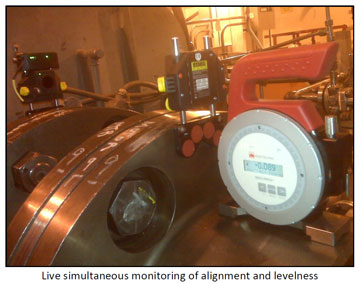
We monitored the alignment and the shaft angle in real-time with both tools and were able to get the leveling and alignment completed all in a single move (See ‘As Left’ condition below.)
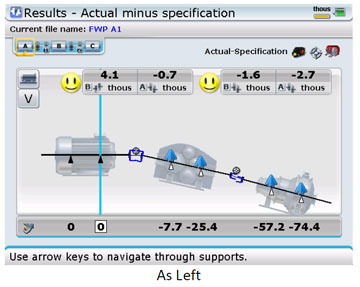
The millwrights worked as an experienced and organized team and got the shim corrections done quickly and safely. We finished the job in 1/4 the time allotted and the plant was able to ramp back up to 100% much sooner than planned. Furthermore, the plant reported that the shaft shuttling has stopped.
by Ana Maria Delgado, CRL
By Deron Jozokos with Shoreline Reliability, LUDECA solutions provider for New England and Eastern New York
Yesterday I visited a customer at a ski resort for an alignment demo and he asked if I would demo our tools on his actual machinery, a recently rebuilt pump that was installed by a vendor. I readily agreed as I thought this would be a good opportunity to show how easy the tool is to use on his actual machinery. After setting up on the pump and motor, we entered the machine dimensions into the SHAFTALIGN® computer and took an initial alignment reading and soft foot reading, and saved the file “As Found”. In addition to a severe soft foot condition and misalignment, I pointed out some other issues with the machines. The shims used previously were undersized for the motor feet, and the washers used under the hold-down bolts were damaged and “cupped”. Also, on two feet the bolt holes didn’t line up with the foundation bolt holes which resulted in the hold-down bolts being cocked.
I recommended that we fix each issue, all of which could be done fairly quickly. We replaced all of the shims with new precut stainless steel shims, eliminated the soft foot, and slid the lower frame laterally so we could line up the bolt holes correctly. From there we re-measured the alignment condition and made the corrections indicated by the SHAFTALIGN system.
We took one last verification measurement and got two Smiley Faces which indicated that the alignment was now within the Excellent range for 1775 RPM tolerances. They were also interested in seeing the new TABALIGN® system in action so we downloaded the TABALIGN from the Google Play Store to their Android tablet, synced it to the same sensors, and took the measurements which repeated exactly the SHAFTALIGN results. They were very happy with the results but at the same time worried about the rest of their machinery which probably has many of the same issues that we had found on this pump-motor set. They’ll be correcting all of those shortly though!
by Ana Maria Delgado, CRL