It can be argued that lubricants are the lifeblood of equipment. It is extremely difficult to assure equipment reliability when lubrication integrity is not maintained. The key is to keep the lubrication system clean, cool, and dry.
According to the Arrhenius Rate Rule, every 18-degree (F) increase in oil temperature in operation reduces oil life by half. Excessive lubrication temperatures can lead to additive depletion, oxidation, varnishing, hazards, corrosion, increased frequency of oil changes, and more. All of this leads to reduced equipment reliability and increased costs.
Reduced operating temperature is one of the many benefits associated with proper machinery alignment. This in turn will help you reduce the operating temperature of the lubricants (lifeblood) within your equipment. Best practice equipment reliability includes proper equipment alignment. Your best practice lubrication efforts should include making sure your equipment is operated within proper alignment tolerances. Doing so will help you maintain the “cool” required to ensure that the lifeblood of your equipment is protected.
by Trent Phillips CRL CMRP - Novelis
Problem: The machine shop of the engineering department of a prestigious Florida university wanted to identify the source of error in their tool room lathe. They had previously observed that when working pieces further away from the spindle chuck, there was an appreciable deviation in accuracy compared with close-to-the-spindle work.
The machine shop instructor suspected the problem to lie somewhere in the tailstock and asked us to confirm or refute his suspicions.
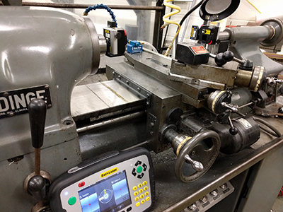
Solution: The Easy-Laser E940 Machine Tool laser alignment system was used to perform three types of measurements:
- Z-axis straightness measurement
- A spindle direction measurement
- A spindle-to-tailstock alignment measurement
In addition, the Values program was used to check for play in the tailstock sub-spindle bearings. An additional check was performed to verify whether the tool support returned to its original position when it was unlocked, and then locked again.
After accomplishing the above measurements and checks, it was determined that the straightness of the Z-axis was within tolerance, the spindle direction was ascertained and the alignment between the spindle and tailstock at the furthest distance revealed a small angle. There was no significant play in the sub-spindle bearings and the tool support check was good.
This data allowed the instructor to narrow down the possible corrective actions to take in order to achieve a better alignment and return the lathe to an optimum performance condition.
The ability to perform all of these checks and measurements to a high degree of accuracy allowed the university to quickly and more certainly identify worn components, which will save them a great deal of money in spares costs, as well as ensure that parts and workpieces fabricated on this lathe will turn out as expected, on time and within design tolerances.
by Oliver Gibbs CRL
May 2016 · Plant Services Magazine
Like a lot of reliability engineers, Joe Anderson, former reliability manager at the J.M. Smucker Co., appreciated – in theory – that precise pulley alignment is critical to preventing vibration problems and ensuring successful operations.
My understanding was, ‘Yeah, we need to do it,’ ” Anderson says. “But you always have these excuses.”
When the Smucker’s plant at which Anderson worked launched a dedicated vibration monitoring and control program a year-and-a-half ago, though, Anderson quickly became a convert to making precision alignment a priority.
The plant purchased a vibration analyzer (VIBXPERT®) and laser alignment tool (the SheaveMaster® Greenline) from Ludeca to help aid in identifying machine defects that appeared to be linked to vibration caused by misalignment. Laser alignment allowed for correcting vertical angularity, horizontal angularity, and axial offset – the three types of misalignment – simultaneously. Whoever was using the laser alignment tool, then, could be sure that adjustments made to correct one alignment problem didn’t create an issue on another plane.
Read the entire article to learn how J.M. Smucker Co. made precision alignment a priority: Get your alignment in line: Don’t jiggle while you work
by Ana Maria Delgado, CRL
There are many tools considered “accurate”. Dial test indicator can measure to the ten-thousandths and gauge blocks can be certified for even tighter tolerances. Even CNC machines can reach ten-thousandth’s accuracy given the right conditions. However, they are tools and they can’t perform to their maximum potential if not used properly or in the right application.
Laser shaft alignment tools follow the same rules. The sensors by themselves have varying degrees of accuracy but how the sensors are used and what application they are used for can vary this accuracy quite a bit. When searching for a “laser alignment system”, don’t be quick to commoditize the term and think all systems are the same just because it uses a “laser”. The most capable systems will work for their intended primary application— general shaft alignment. Should a specialized application arrive, such as an uncoupled spacer shaft with limited rotation, a system that has more functionality will be able to immediately handle the job over a basic system.
LUDECA can assist you in your decision. We provide a network of local solutions providers who are your highly experienced advisors for navigating all of the choices that a quick internet search can provide. They will make sure you know you are getting the right tool for your needs whatever your budget. We also have a team of engineers that will guide you in your applications. All this is provided for free! This is something to consider when purchasing on price alone. We will be there when you need us the most.
So let’s go back to the dial indicators, gauge blocks, and the CNC machine – they are not accurate in use without a trained operator. The same principle applies to laser shaft alignment. Most of our laser shaft alignment systems currently have 1-day free training on-site at your facility by your local solutions provider. Our laser shaft alignment tool is designed to improve your reliability and thereby reduce downtime. Avoid costly mistakes and wasted time by ensuring your operators are well trained to use these tools to their maximum potential.
by Daus Studenberg CRL
Often, welding operations such as MIG and TIG will be occurring in the presence of your laser shaft alignment system. The question often comes up: will this light energy damage the optics? The answer is no.
However, if you must weld in the presence of your laser alignment system, a greater source of damage could be from the heat, sparks, and electrical energy that is emitted from the process. We do not recommend leaving equipment attached to anything being welded due to these dangers. Welding is like having a continuous lightning strike occur and electrical voltage differences and resulting magnetic fields could cause electrical damage. Remove your equipment to protect it from such hazards.
As far as light energy goes, OSHA has standards for minimum eye-protective shade numbers ranging from “4” for gas welding to “11” for shield metal arc welding and finally up to “14” for carbon arc welding processes. NASA recommends a number “14” for directly viewing solar eclipses. All of this is for protecting the human eye, which is less resistant to damage from light than a laser detector. A laser detector is designed to continuously absorb direct laser light energy over a continuous period of time. This is far more light energy than the human eye would encounter from arcs and sunlight with proper protective gear. Warning labels caution you not to stare directly into the laser beam!
Many laser alignment systems have a special protective coating on the detector that is optimized for the specific laser wavelength of light it is intended to detect. This helps prevent interference from the bright sun from causing measurement errors. Many laser systems are used in bright sunlight, and some work better than others under such conditions. Since the welding energy would at most be of the same intensity as direct sunlight, this would most likely not cause damage. Of course, you could also put the protective caps on to be completely safe.
by Daus Studenberg CRL
The Mars Climate Orbiter was launched by NASA on Dec 11, 1998, to study the Martian climate. On its arrival at Mars on September 23, 1999, communication was lost shortly after an orbital insertion maneuver was performed.
The cause of the failure was a lower than anticipated altitude with a resulting burn-up of the orbiter. It was entirely due to human error. The error occurred because one piece of software entered the required force in pounds and a separate piece of software interpreted this as newtons. The result was a $125 million dollar lesson on the importance of consistency in units.
When performing an alignment, consistency with measurement units is the key to preventing costly errors. We recently conducted a training class for a company that worked on the metric system. Our alignment systems allow for easy conversion “on the fly” between imperial and metric units, so we simply operated everything in the metric system. We then started noticing that some students were taking much longer times on their alignments than usual. It became apparent they were misinterpreting the values of the shims, which are expressed in “thou” and thought they represented some form of a metric value. Fortunately, it was not a $125 million mistake as this can simply be a lesson to be learned in training.
When working with different units, consider all of the stakeholders involved in the project. Who will operate the tool? Who will make corrections? Who will interpret whether or not the alignment is acceptable? You will have to determine which units of measurement will be the standard for the entire project. Fortunately, if someone makes a mistake with units for corrections, they will most likely not see the alignment improving. However, if there is a mistake on units for acceptability criteria, this could be dangerous. There is a big difference between 1 mm and 1 thou! Avoid multiple conversions for the alignment process. Standardize on one set of units and remain consistent for the whole project. If there is a need to convert units during the alignment, make very sure everyone understands when this happens and why this is the case.
by Daus Studenberg CRL
In today’s world, video platform is the way to accomplish effective visual knowledge and a learning mechanism in many organizations. With the use of video, one not only is able to promote products and services but one can also strengthen a culture and demonstrate how-to scenarios easily and quickly.
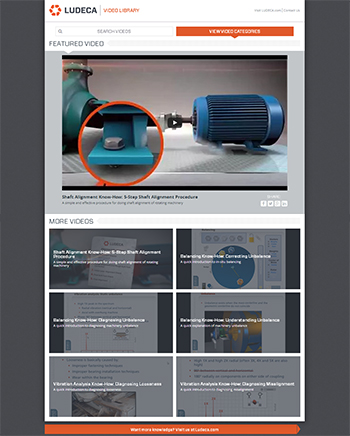
LUDECA believes in communicating visually to help customers educate and train their personnel on precision skills. For this reason, we are pleased to announce the release of our new microsite www.LudecaVideos.com, which features a Shaft Alignment Know-How series plus a Know-How series for Vibration Analysis and Balancing. The video site features basic terminology, fundamental concepts, advanced measurements as well as product demonstrations. The videos are indexed by category but also searchable by keyword.
We felt there was a need to go back to basics and help educate on precision skills and related technology to improve asset reliability. Following the Uptime Elements™ holistic approach to reliability, alignment and balancing are key components of your asset condition management (ACM) program. We are happy to offer these videos to our customers for their personnel to access and for use in their training programs. We hope this content assists them and others in either improving their reliability program or in getting one started and leads to world-class reliability programs,” —Frank Seidenthal, president of LUDECA.
We encourage you to visit www.LudecaVideos.com and see for yourself the value behind each video.
by Yolanda Lopez
Guest post by Jeff Shiver, Founder of People and Processes, Inc.
As a maintenance planning and scheduling professional, I am often asked how to schedule maintenance activities when production is 24/7 or 24/6. An important question is whether the 24/7 operation is driven in part by a lack of reliability or if the organization is proactive and actually capacity constrained. In either case, the challenge is finding windows for work with the equipment stopped or shut down.
- Failure to identify smaller windows for work
- Give work to operators
- Lack of partnership between the operations and maintenance group
- Get the work done right
- Make resources available
- The right focus on preventive maintenance (PM)
- Identify failure
- Act, don’t react
- Don’t defer PM tasks
- Failure to take advantage of unplanned downtime for proactive work
- Manage the backlog
- Lack of effective coordination between the crafts
For more details, please read the full article.
by Yolanda Lopez
I recently participated in an alignment done on a boat. The alignment was between a diesel engine and V-transmission connected by a cardan shaft.
The Challenges:
- The offset between the gearbox and motor was a little over 1 inch.
- Aligning the engine to the transmission without removing the cardan shaft.
- Alignment is difficult because it has to be done while the boat is in the water, which means conditions can vary as the job is being performed.
The Solution:
- Use a ROTALIGN® ULTRA laser alignment system with compact magnetic brackets, which allow mounting the components even in very tight spaces. See Figure 1.
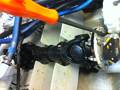
Using the Multi-point measurement mode allows measuring accurately even with the waves affecting the stability of the boat. This measure mode allows us to increase the number of points collected at each arbitrary measurement position. Multi-point also lets us use the “InfiniRange” feature which allows extending the measurement range of the detector during a set of readings, thus making it very easy to cope with the large misalignment across the cardan shaft.
by Carlos Bienes CRL
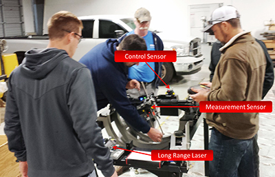
The need for bore alignment applies across a wide variety of industrial sectors including the marine industry, energy, oil and gas, chemical, and service companies. It is used to determine the centerline of a series of bores and setting the centerline relative to any fixed reference, or aligning the bores to a rotating shaft, and/or determining the out-of-roundness of bores. One common example is the alignment of large gas and steam turbines.
However, one problem often encountered with performing laser alignment on large turbines is that over long distances and long measurement periods, laser stability is subject to be impacted by variations in air density, temperature, or light, the cumulative effect of which is often referred to as “laser drift”. To ensure measurement accuracy, an additional fixed sensor, called a control sensor, can be installed to monitor the amount of laser drift at the far end of the turbine. When used with the CENTRALIGN® ULTRA EXPERT application, the laser drift data from the control sensor is automatically applied to the bore measurements taken by the measurement sensor to provide true bore center measurements under any conditions over longer periods of time.
by Tim Rogers CRL
- Right safety procedures before you align.
- Right machines to align.
- Right alignment procedure.
- Right alignment tool.
- Right alignment tolerances.
- Right alignment targets.
- Right soft analysis and correction.
- Right shims.
- Right moves.
- Right bolt tightening sequence.
- Right bolt torquing.
- Right alignment report.
by Ana Maria Delgado, CRL
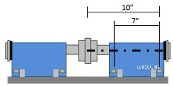
When using short-flex coupling tolerances, the centerline of rotation of each machine is aligned at the coupling center, which is the center between the flex planes, or the average center of power of transmission points. Using simple geometry, it’s easy to see why short-flex coupling tolerances are too tight when using spacer couplings. In this example, the only variable is the axial length of the coupling. A small short-flex coupling is compared to a long spacer coupling, but the machine used and feet corrections remain the same. This makes it easy to see how the length of the coupling affects the movement of the centerline of rotation at the coupling center.
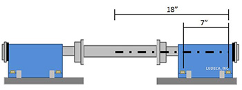
The dimensions required for this example are shown in the figures below. In Figure 1, the front and back feet of the machine are 7″ apart. The distance from the back feet to the centerline of rotation at the coupling center of the short flex coupling is 10″. In Figure 2, the latter dimension, which is 18″, represents the distance from the back feet to the center of a 16″ spacer coupling. Note that this coupling center extends 8″ (half of the spacer coupling length) past the first flex plane or first point of power transmission.
In the next step, a 2-mil shim is added to the front feet of the right machine, and the back feet are left untouched. This correction is arbitrary and can be represented using three equivalent triangles as shown below.
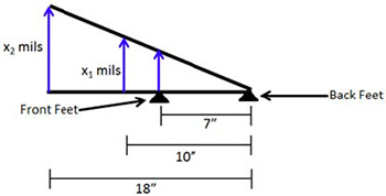
The total movement of the centerline of rotation at the center of each coupling type is represented by x1 for the short coupling (Figure 1) and x2 for the spacer coupling (Figure 2). These values can be found by setting the ratios of each triangle’s legs equal to each other.
(1 “mil” )/(7 “inches” )=(x_1 “mils” )/(10 “inches” )=(x_2 “mils” )/(18 “inches” )
The figure below shows the total movements at the coupling centers.
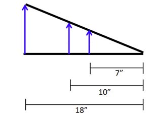
After adding 2 mils to the front feet of the machine, the centerline of rotation moved 2.9 mils at the short-flex coupling center and 5.1 mils at the middle of the spacer coupling. That’s a 76% larger movement at the spacer coupling center! This goes to show that the further away the coupling center is from the moveable machine’s feet, the more sensitive the movement will be. It may take all day to align the machine with a spacer coupling to short-coupling tolerances because a small movement at the feet turns into a large movement at the coupling center. The machine may even be aligned within an appropriate spacer shaft tolerance, but the tool will still show that there is misalignment if short-flex coupling tolerances are selected. As a rule of thumb, if the coupling length is smaller than 4″ between flex planes, use short-flex tolerances. If this distance is greater than 4″, use spacer shaft tolerances and make your life easier.

by Silvio Attanasio CRL
When there is a lack of repeatability, or unexpected results are obtained during laser shaft alignment, a simple functionality test can be performed on the alignment tool’s heads to determine if they’re working properly. This can be achieved on a laser-and-sensor system, such as the ROTALIGN® ULTRA IS, or a transducer-and-prism system, such as the SHAFTALIGN® OS3. If the system passes the functionality test, it is most likely working properly. However, this test does not replace an official calibration check.
Perform the following procedure if there is doubt that your laser alignment tool’s heads are not working properly:
- Mount the heads on a piece of stiff pipe about six to ten inches apart. Do not use pipes that are smaller than two inches in diameter. Also, do not use solid shafting or bar-stock. The pipe does not have to be perfectly straight, but its surfaces should be smooth enough for the brackets to be mounted on.
- Enter the dimensions. Use the halfway point between the heads as the coupling center. Set the coupling diameter to ten inches. The remaining dimensions are irrelevant.
- It is ideal to mount the pipe on V-blocks, but this step can be performed with your hands as well: Center the laser beam on the dust cap. Remove the dust cap and take a set of readings while rotating the pipe 360 degrees. The coupling results should be zero or very close to it.
- Repeat this procedure at least four more times. Position the laser at different locations on the detector each time.
It’s as simple as that. If the coupling results are not consistently close to zero, the heads will likely need to be calibrated. We recommend that you have your heads calibrated every two years for optimal performance.
by Silvio Attanasio CRL
LUDECA Inc. has been recognized by the Society for Maintenance and Reliability Professionals (SMRP) as an approved provider of continuing education and training aligned with key subject areas related to reliability and physical asset management.” said Ron Leonard, SMRP CMRP Chair of APEP Committee
![]() As an SMRP Approved Provider, LUDECA is recognized for its best-in-class continuing education training programs for precision shaft alignment of rotating equipment and precision balancing as part of reliability and physical asset management. LUDECA is a Tier 2 Approved Provider with courses that are taught on-site, regionally, or at their own state-of-the-art training center in Doral, FL.
As an SMRP Approved Provider, LUDECA is recognized for its best-in-class continuing education training programs for precision shaft alignment of rotating equipment and precision balancing as part of reliability and physical asset management. LUDECA is a Tier 2 Approved Provider with courses that are taught on-site, regionally, or at their own state-of-the-art training center in Doral, FL.
The following are currently approved courses that map to SMRP’s Body of Knowledge Pillar #3 – Equipment Reliability:
- 3-day Advanced Shaft Alignment Course (21 hours)
- 4-day Comprehensive Shaft Alignment Course (28 hours)
- 3-day Balancing Course (21 hours)
We are thrilled to be part of this select group of training companies.” says Ana Maria Delgado, CRL, Marketing Manager for LUDECA. “Our company has always made it a priority to deliver quality hands-on training with alignment and balancing best practices to improve asset reliability. Our new SMRP Approved Provider status provides us with the opportunity to enhance our commitment to our customers and to the success of their reliability programs.”
About LUDECA
LUDECA is a leading provider of Preventive, Predictive, and Corrective Maintenance Solutions, including machinery laser alignment, vibration analysis, and balancing equipment as well as software, rentals, services, and training. For more details, visit www.ludeca.com
About SMRP
The Society for Maintenance & Reliability Professionals (SMRP) is an international, nonprofit society dedicated to promoting excellence in maintenance, reliability, and physical asset management. Its 4,000 members specialize in achieving improved efficiency and profitability across many industries by applying best practices and proactively managing operations, equipment, and people. SMRP provides ANSI-accredited professional certification to validate the critical knowledge and skills of the top practitioners in the profession. For more information, visit www.smrp.org.
by Ana Maria Delgado, CRL
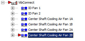
A customer with a need to monitor machinery remotely and limited to a small budget invested in the VIBCONNECT® RF system to keep their machines running. During a routine check of the data, it was noticed that a certain machine was in alarm. The OMNITREND® software easily identified the machine that was in alarm by the red indicator (see Fig. 1).
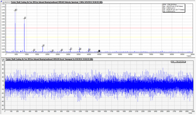
The customer contacted LUDECA to assist in analyzing the issue. The frequency did not match any of the components given for this machine. The waveform data showed extremely high levels of vibration and indicated that something was seriously wrong with this machine (see Fig. 2).
It was suggested that the machine be visually inspected for any abnormalities, including a strobe for the visual inspection. The strobe was locked into the known frequencies that were showing in alarm. The customer was able to identify that a broken belt was the cause of the high vibration levels (see Fig. 3).
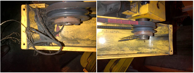
New belts were installed and the pulleys were properly aligned using the DotLine Laser pulley alignment tool to prevent future belt failures due to misaligned pulleys.
by Mickey Harp CRL
Thermal growth compensation has become fairly routine among laser aligners. For machines that run at high temperatures, most manufacturers will recommend a target to align to that compensates for the thermal growth that the machine is expected to undergo. That target only tells half of the story though. In many of the situations we see, once operating, there may be more horizontal movement than vertical, and both movements are often far different from the specified amounts. These differences usually arise from sources such as pipe stress, foundation looseness, operating load variances, and other factors.
To ensure perfect alignment under operating conditions, you can monitor the positional change of machines at your plant using the ROTALIGN® ULTRA and Live Trend module. During your next shutdown, mount the lasers to the machines and monitor the cooldown. During the shutdown, align the machines using your newly discovered targets and even verify the accuracy by re-measuring the positional during start-up and run-up to final operating condition.
by Tyler Wulterkens CRL
You’ve just completed your horizontal live move and you’ve re-measured to double-check your results. Now, it seems your coupling results are not at all what you were expecting. Does this sound familiar?
All too often when this occurs, the reasons are quite simple, such as some residual soft foot, or coupling strain that affected the accuracy of your initial readings. But if you’ve already eliminated these causes, perhaps the cause is more basic.
Double-check your dimensions screen again. It’s not that uncommon to “fat-finger” the values. Perhaps, intending to enter 2.5 inches you accidentally entered 25 inches instead! Also, make sure the units (mm or inches) are correct while you’re there.
Another often overlooked detail is the process of moving itself. Care must be taken when performing any move to prevent the laser systems heads from being bumped or jarred. Laser alignment is a very precise business and the detectors can “see” very fine movement. Unintentional movement of the laser/detector from hammer blows to the machine can cause a false reading to occur giving you an inaccurate representation of the final move result.
Always use jackscrews whenever possible!
by Oliver Gibbs CRL
The “Move Simulator” program is extremely useful on all types of machines but we have found it most helpful on multi-coupling train units.
We recently performed an alignment on a 350 HP turbine/gearbox/pump train in one of our cracking units. The turbine had been replaced by the area Maintenance Group and the machine was supposed to be a like-for-like drop-in exchange. This was not the case for this unit. Two problems: A bolt-bound condition and height difference on the turbine. Due to time constraints, removing the turbine and modifying support feet was not a viable option.
We used the Rotalign® ULTRA IS, took readings on both couplings and then used “Move Simulator”. We were able to adjust the gearbox height and move it horizontally to achieve acceptable alignment to the turbine. The pump side had been found almost perfect (per targets) and we ended up maintaining the offset but disturbed the angularity slightly but remained within tolerance for the coupling.
The “Move Simulator” was certainly a time and labor saving program on this occasion. —J.W., Reliability Technologist – Eastman Chemical Company
by Ana Maria Delgado, CRL
Precision alignment is an essential part of a proactive reliability program as it can eliminate many machine failures and defects. This Infographic outlines an easy and effective way to align your rotating equipment.
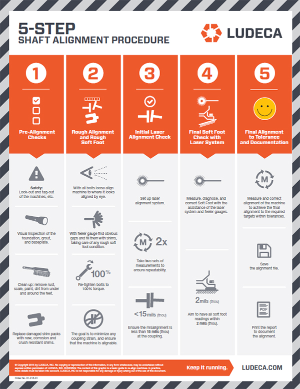
Download Infographic
by Ana Maria Delgado, CRL
A few weeks ago, I was at an engine manufacturing facility, training the technicians on using our ROTALIGN® ULTRA IS Laser Alignment System. They were using it to align their engines for proper testing. To begin, the technicians rough-align the engine. To test the engine, they couple it to a gearbox with a 5-foot-long spacer coupling. They set up the laser and receiver at 12 o’clock and then turn the shafts clockwise, using Continuous Sweep mode. In one instance, at about 45 degrees of rotation, they ran out of measurement range. Due to a combination of the long separation between laser and receiver, the large misalignment, and the small amount of rotation, they were not able to achieve good repeatability.
So I suggested the following solutions:
First, I recommended zeroing the laser at the 12 o’clock position but starting the measurement at around the 10 o’clock position and rotating clockwise. They were able to achieve a rotation of about 85 degrees and obtain great repeatability. The customer’s comment was “We are used to starting the measurements at the 12 o’clock position from old dial indicator practices”. It may be convenient to zero the laser in the 12 o’clock position, but you can start taking readings at any rotational position, even with the beam at the edge of the detector range. This way you can maximize the measurement range of your laser alignment system.
Secondly, I suggested that they zero the laser at 12 o’clock and start rotating the shafts while observing on the computer screen in which direction the laser beam moves on the detector. Stop the shafts and readjust the laser beam as far as possible in the opposite direction to the observed movement. Start taking readings in that position, and again this will maximize the measurement range of the detector and consequently also increase the amount of shaft rotation you can get before running out of range. If you can achieve at least 70 degrees of rotation, you will obtain accurate readings.
I also made a third suggestion: If the misalignment is so bad that you cannot obtain 70 degrees of shaft rotation before you run out of measurement range, no matter how far you initially adjust the beam in the opposite direction to its track, then use “InfiniRange”. This feature is available in the Multipoint measure mode and lets you stop to readjust the beam while taking readings, as often as necessary in order to achieve the necessary rotation to get good readings.
So, keep these ideas in mind and no amount of misalignment will ever stymie you in the field again!
by Adam Stredel CRL