Condition Monitoring Expert Tip #10 by Mobius Institute
No, sadly, that is not right. Unless the person has been properly trained, unless the company has specified precision alignment tolerances, and unless the training is followed and the tolerances are achieved, then you are not performing precision alignment.
We see this as a very common problem. Laser alignment systems can achieve terrific results. And a precision-aligned machine is far more reliable than a machine that has been “roughly” aligned with an alignment system, and far superior to a machine aligned with a straight edge. But if your maintenance technicians do not appreciate why that last shim should be installed, and why the motor must be moved such a small amount to the left or right, then those corrections will not be made – and yes, it does matter.
Research by Tedric A. Harris, in the book “Rolling Element Bearing Analysis” (John Wiley & Sons), showed that just 5 minutes (5/60 of a degree) of angular misalignment can reduce the life of a bearing by half. Yes, precision matters!
by Yolanda Lopez
Condition Monitoring Expert Tip #5 by Mobius Institute
Now, this is a tricky question to answer… We have a few contenders: high-frequency vibration analysis, regular vibration analysis, ultrasound, oil analysis, wear particle analysis, and infrared analysis. Let’s start by ruling a few of them out.
Infrared analysis is used to detect heat in a bearing, which is a late-stage fault condition, so that’s not your best option. Regular oil analysis can detect the presence of the wear metals within the bearing, but wear particle analysis is a better tool for that. Regular vibration analysis (i.e. velocity spectra) provides very clear indications of bearing faults, however, the high-frequency detection techniques provide an earlier warning. That leaves high-frequency vibration analysis, ultrasound, and wear particle analysis.
Ultrasound is the easiest to use. Push the probe against the bearing and listen carefully and you will hear if the bearing is in distress. (You can also record and analyze a waveform, but now you may as well be performing vibration analysis). Many would argue that high-frequency vibration analysis (such as enveloping, PeakVue, shock pulse, and others) provides a clearer indication of the nature and the severity of the fault. But it does require more training and potentially a more expensive system to perform the collection and analysis.
And that leaves wear particle analysis. Let’s just say that if you own critical gearboxes, you absolutely must perform wear particle analysis. Performed correctly, you will detect the first signs of wear, and complex gearboxes provide a greater challenge for the vibration analyst and the ultrasound tools.
Although I haven’t really answered the question, I am hoping to have put you in a position to make the right decision for your situation.
Thank you Mobius Institute for this valuable tip!
by Yolanda Lopez
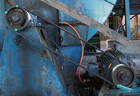
Belts are a critical part of the design and function of belt-driven equipment. The majority of belts never reach their intended design life due to improper selection, storage, and installation. Unfortunately, this results in compromised equipment operation, lost capacity, and increased costs. Do not condemn your equipment to death through improper belt installation practices. Below are some guidelines to help your facility ensure belt-driven equipment reliability:
- Follow all site-specific safety procedures.
- The same basic installation steps are required for both synchronous and V-belts.
- Loosen motor mounting bolts or adjustment screws.
- Move the motor until the belt to be replaced is slack and can be removed easily without prying or any other means of force. Prying off a belt or chain can damage a sheave or sprocket and increase the risk of injury. Never use a screwdriver to remove belts, because this may damage belt cords, sheaves, and sprockets.
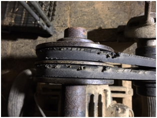
- After removal, inspect the old belt for unusual wear that may indicate problems with design or maintenance issues.
- Visually inspect and replace sheaves or sprockets that have excessive wear, nicks, rust, pits, or are bent. Grooves that appear “shiny” or polished could indicate heavy wear and should not be ignored. Never sand or scrape groves. Doing so will insert points of wear leading to a premature belt or sheave failure.
- Sheave gauges should be used to measure for excessive wear and determine if sheave replacement is necessary. Total wear should not exceed 1/32 in or 0.8 mm.
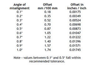
- Sheaves and sprockets should be checked for proper alignment. A laser alignment tool is the recommended means. Most major belt manufacturers recommend a nominal tolerance of 0.5 degrees. However, better alignment tolerances should be achieved if possible. The table below can be used to determine proper alignment.
 For maximum resolution, always mount the laser alignment tool on the smaller sheave and the targets on the larger sheave. Ensure that the alignment tool being used can indicate misalignment in all three degrees of freedom (axial offset, horizontal angularity, and twist angle).
Note 1: Check and correct any run-out conditions prior to belt installation. Tighten bolts in the proper sequence to prevent axial run-out.
Replace all belts on multiple belt drives with new belts from the same manufacturer. Never replace a single belt or a portion of a multiple belt drive. Mixing old and new belts will create unevenly shared loading and lead to premature belt failure and/or sheave wear.
- When installing the new belt, ensure that enough clearance is available to slip the new belt(s) over the sheave or sprocket. Never pry or use force to install the belt(s). Never use a screwdriver to roll belts into position, because this may damage belt cords, sheaves, and sprockets.
- Adjust the motor base until the belts are tight. The motor should be checked for soft foot conditions using a feeler gauge or other suitable means and corrections made if required. No reading of soft foot should be greater than 0.002 inches or 0.05 mm.
- Use a tension gauge or sonic tension meter until the correct tension is measured according to specifications.
- Rotate the belt drive by hand a few revolutions and re-check and adjust belt tension as necessary.
- Re-check the sheave or sprocket alignment and re-adjust if necessary.
- Secure motor mounting bolts to the correct torque specifications.
- Replace equipment guards and follow any other site-specific safety requirements to return the equipment to operation.
- Upon equipment startup, listen and visually inspect for any unusual vibration, noise, or heat. Other corrective actions may be required (lubrication, tension adjustment, etc.) to ensure equipment is ready for proper operation.
Note 2: Contact the belt manufacturer and provide the drive information to receive the most accurate tension information for the required operating loads. Belt tension charts may specify more tension than is required by the application. The proper tension for the belt is the minimum tension required to prevent the belt from slipping at maximum load. A good guideline in the absence of any other information is to use a spring scale and press down on the belt in the approximate center of its span (on the tight side), to deflect the belt 1/64″ per inch of span length and observe the force required to do so. If you are not sure of the belt span length you may also use the center-to-center distance of the pulleys, which will be similar. Tension the belts until the force required for this deflection equals the belt manufacturer’s maximum recommended force values for the specific belts you are using.
Note 3: Belts should not squeal on startup when adjusted to proper tension. This can be an indication that the drive is not proper for the application.
Note 4: A run-in procedure may be required for V-belt drives or other installations to ensure optimal belt life and equipment reliability. It is recommended to check and adjust belt tension under full load after 20 minutes, 24 hours, and 48 hours of operation to properly seat the belts in the sheave grooves. Consult belt manufacturer and engineering specifications to determine if a run-in period is required and the length of time.
by Trent Phillips CRL CMRP - Novelis
Unfortunately, proper storage of belts is often overlooked. I visit a lot of plants and almost always see equipment belts improperly stored to the detriment of optimal reliability. Ensuring that the belts used in your equipment are properly stored will result in:
- Fewer failures upon startup
- Longer belt service life
- Better equipment performance
- Improved safety
- Preservation of belt warranty coverage
Below are some belt storage tips to help ensure that your equipment functions as healthily and long as possible:
- Belts should be stored in a cool and dry environment with no direct sunlight. Storage temperature should be below 85°F/29.5°C with a relative humidity no higher than 70%. Belt performance is reduced by 50% for every 15°F / 9.5°C above 115°F / 46°C.
- Do not store belts in areas exposed to:
- Airborne chemicals
- Heat sources
- Direct sunlight
- Airflow from heat sources
- Transformers, refrigerators, motors, or other sources that create ozone
- It is not recommended to store belts on the floor. If floor storage is required, the belts should be stored in a protective container and never exposed to foot traffic.
- Never twist, bend or crimp belts during storage and handling. Doing so will damage them.
- Do not hang belts from pegs as they will distort over time. Do not store belts under any state of tension.
- V-belts may be stored by hanging on a wall rack only if hung on a saddle with a diameter at least as large as the minimum diameter sheave recommended for the belt cross-section. If coiling a V-belt for storage, consult the supplier for limits. It is always best to store belts flat on a shelf.
- Store belts in the original box. Stacking of belts on top of each other should be limited. Ensure that the belts on the bottom are not damaged by the weight of the belts on top.
by Trent Phillips CRL CMRP - Novelis
As Published by Maintenance Technology Magazine September 2017 issue
If greater reliability and uptime are of any concern to you, then precision maintenance is a key component in achieving it. This means having clear and simple, yet meaningful, procedures in place for the different tasks involved. Two such tasks are precision alignment and balancing. LUDECA’s 5-Step Procedures will help guide your facility and maintenance staff to achieving precision maintenance.
Get your own copy of these 5-Step Procedures:

Download 5-Step Shaft Alignment Procedure

Download 5-Step Balancing Procedure
Why is precision maintenance so important? The reasons are clear:
- Safety
The alignment and balancing procedures lay out the basic steps required to align and balance machines safely, reducing the risk of injury and increasing the likelihood of a quality outcome. Checklists simplify the workflow and serve to remind employees of the processes required to consistently and safely perform the precision maintenance task. - Reliability
Well-aligned and balanced machines run more reliably, with a greatly reduced probability of failure. This allows for better maintenance planning, greatly reduced repair and maintenance expenses, increased uptime, and more profits. - Efficiency
A good alignment procedure ensures that machines are aligned to the proper tolerances for the running condition of the machines, taking into account such things as thermal growth and anticipated positional changes. This ensures that the greatest efficiency is achieved in your running machinery, prolonging their health and reducing power consumption. Studies have shown that well-aligned machines result in a 3% to 10% reduction in power consumption. Noise and heat generation are reduced, producing a safer work environment. - Production Quality
Good alignment and balancing result in better product quality since vibration is minimized, resulting in more uniform and higher product quality. Unexpected breakdowns in production machinery may lead to costly waste from scrappage and high restart costs for the production line. - Training & Procedural Consistency
Once implemented, a procedure ensures all employees involved in the activity face clear and consistent expectations and processes, leading to a better understanding between all staff in the facility. Training expenses can be reduced since often only refresher training is required to update understanding of the technology utilized as updates are rolled out. Records should be kept that document employee training.
The next step in precision maintenance and reliability is the Implementation of formal specifications that detail every step in a task from safety to activity process to documentation, to ensure that anyone involved can follow the procedures and guidelines without confusion, and reach the desired outcome for all machinery types in the plant. Such specifications typically take from two to three months to develop and a further two to three months to roll out and fully implement. LUDECA has written a number of these specifications for customers worldwide. Let us help you as well.
by Alan Luedeking CRL CMRP
Condition Monitoring Expert Tip #3 by Mobius Institute
This tip is sponsored by IMVAC (International Machine Vibration Analysis Conference)
How do you decide which assets should be monitored? How do you decide whether you can justify the use of more than one technology? Criticality analysis provides a means to prioritize which assets will be monitored and how much effort will be put into collecting data and performing the analysis.
Criticality analysis considers several factors. It will consider the consequences of failure, for example, health and safety, harm to the environment, downtime and production losses, availability of spares, cost of spares, etc. It will also consider the reliability of the asset; how likely is it to develop a fault condition. And it should also consider the detectability of the fault conditions. Therefore, an unreliable asset where failure would lead to dire consequences and where we currently cannot detect the onset of failure absolutely requires condition monitoring and can justify multiple technologies. At the other extreme, a reliable asset’s minimal consequences of failure may not require any condition monitoring; we may employ “run to failure”.
Criticality analysis enables you to make the best use of your limited resources.
Special thanks to Mobius Institute for allowing us to share this condition monitoring expert tip with you!
by Yolanda Lopez
It seems that every maintenance department has a hard time installing bearings because of the problems inherent in conventional heating methods.
Applying care, good technique and heating methods are better. Over 90% of rotating equipment has defects at startup that can result in equipment failure.
One reason bearing installation is often a herculean task is not using proper heating methods. Excessive heat applied to the bearing during installation can introduce defects that lead to premature equipment failure. Instead, heating a bearing on an induction heater, automatically demagnetizing it, and then slipping it on the shaft free of stresses is the way it should be done. The results of overheating a bearing are increased maintenance costs, increased safety risks, and more equipment downtime.
Proper heating methods and best practices should be applied to correctly install bearings. Induction heaters such as SURETHERM can help eliminate induced bearing defects due to poor fitting and improper mounting techniques. Induction bearing heaters provide increased safety, and increased efficiency and reduce the risk of bearing contamination and damage that can result from using brute strength, oil baths, blowtorches, or other improper methods of heating bearings for proper installation.
Here are some conventional methods that are used in Industry and why they are not the way to install bearings:
Heating a Bearing with a Blowtorch
 – No temperature control
– Risk of overheating
– Grease leaks out of the bearing
– Tension in material
Heating a Bearing using a Hot Plate
 – No temperature control
– Risk of overheating
– Grease leaks out of the bearing
– Tension in material
– Dangerous (plate stays hot)
Heating a Bearing in an Oil Bath
 – Slow heating process
– New grease cooks off the bearing
– Dangerous (hot oil)
– Environmentally unfriendly
Heating a Bearing in an Oven
 – Slow heating process
– High energy consumption
– Grease leaks out of the bearing
by Bernd Seidenthal CRL
Condition Monitoring Expert Tip #2 by Mobius Institute
This tip is sponsored by IMVAC (International Machine Vibration Analysis Conference)
How do you decide how often measurements should be taken?
Regardless of the condition monitoring technology, you must decide how often measurements will be taken. At one extreme, it could be a permanent monitoring system that takes measurements every split second of every day. On the other extreme, it may be infrared analysis that is performed once a year. But how do you make that decision?
The most common answer we receive is that it is based on the criticality of the equipment. More frequent measurements are taken on the more critical equipment. The next most common answer is that it is based on reliability. If you have been monitoring a machine with vibration analysis every 30 days and have not detected a fault for a year you may decide to test it every 60 days, or 90 days. Now, it is true that you have to decide how best to use your precious time. But the one factor often forgotten is the “PF interval”.
The PF interval, also known as the “lead time to failure”, is the time between when you can detect the fault condition and when the equipment will have “functionally failed” – i.e. it can no longer be used. If we use the right technologies with the correct settings and we take frequent measurements, then we will get the earliest warning, and therefore we have the greatest lead time to act. However, if the PF interval is short, then it is possible that if you have extended the measurement period to 90 days, the equipment may develop a fault and fail before you take the next measurement.
There is a lot more that could be said on this topic but suffice to say that it is essential that you understand the PF interval and continue to monitor equipment so that you take at least two measurements between the time the fault is detectable and when the asset will have functionally failed.
Special thanks to Mobius Institute for allowing us to share this condition monitoring expert tip with you!
by Yolanda Lopez
Guest Post by Bob Dunn from I&E Central, Inc.
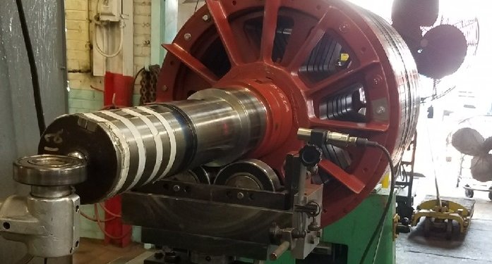
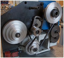
A customer was having difficulty balancing the rotor shown above. They had made multiple corrections, some contradictory, and were worse than when they started. In that this is on a shop stand and under controlled conditions, something was not right. Looking at the photo, I saw a couple of likely issues.
- The shaft is pretty reflective itself, it is doubtful that they were getting a good or consistent phase reading. I recommended they put a ring of black tape on the shaft, with the reflective tape on the black.
- The tach sensor is pointing at the shaft at about a 90-degree angle. Optical sensors and reflective tape works better if the sensor is aimed at an angle – 30 degrees or so.
- The tach sensor is pretty close to the rotor. In this case, it is not too close, but you can be too close. A sensor like this will work from several feet away, if you are having problems, try moving the speed sensor further away.
The customer applied the tape and adjusted the tach position. The rotor was balanced in a single run.
by Yolanda Lopez
Condition Monitoring Expert Tip #1 by Mobius Institute
This tip is sponsored by IMVAC (International Machine Vibration Analysis Conference)
How do you decide which condition monitoring technologies to use?
There are many condition monitoring technologies that we could employ. And within each technology there are sub-technologies. For example, within vibration analysis, we can use high-frequency analysis, spectrum analysis, time waveform analysis, and phase analysis. Within each sub-technology, there are settings we must select. For example, we must set the frequency range when collecting spectra. But which technologies should we use? Which settings are correct? The best way to make those decisions is by understanding the failure modes of the equipment.
If you understand what leads to failure, and what is likely to fail, you can select the most appropriate technologies and settings. You may argue that that is an obvious statement to make. You are probably not using vibration analysis on your steam traps… But after 30 years of experience in vibration analysis, it is common to see that fault conditions a totally missed because of the misapplication of the technology.
It is not necessary to perform a full RCM (reliability-centered maintenance) or FMEA (failure modes effects analysis) to make this determination. A so-called “accelerated RCM” is sufficient to ensure that you make the right decisions.
Special thanks to Mobius Institute for allowing us to share this condition monitoring expert tip with you!
by Ana Maria Delgado, CRL
There are two commonly used testing methods to determine a vertical pump’s natural frequency. The first method is called a startup or coast down. In order to perform this method, a tach signal is required for the speed to be tracked. The pump is started and the amplitude and phase are recorded during start-up and coast down, however, when a pump is started across the line (connected directly to a power source without a drive or soft-start circuit) it is very difficult to use this method. The problem is that when a pump is started across the line it goes from zero rpm to full speed so quickly that there is not enough time to obtain valid data. The coast down method is not normally successful in these cases. When the stop is initiated the pump comes to a complete stop in a very short period of time as the liquid inside the pump column falls back to the wet well acting as a brake. However, start-up and coast-down testing can be performed successfully if a pump is being operated using a VFD (Variable Frequency Drive) as the rate of speed can be controlled.
The other method of determining structural natural frequencies on a vertical pump is to conduct an impact test. This test is more commonly known as a bump test. This test requires that the pump be stopped and impacted using a block of wood or a large hammer that has a soft tip (modal hammer). The bump test provides a response curve that will identify the natural frequency and/or frequencies of the pump. It is recommended that the testing be performed in two separate directions. One direction would be in-line with the pump’s discharge pipe and the other direction should be 90 degrees from the discharge pipe. The two different directions will usually result in two different natural frequencies as the pump’s discharge pipe tends to stiffen the structure. This vibration data can be shown as a higher natural frequency from that direction. The other direction which is 90 degrees from the pump discharge will usually have a lower natural frequency. This is due to the fact that the pump manufacturers typically cut out part of the structure. This allows access to the coupling or seal which also dampens the structure in that direction.
Both of the mentioned methods can assist with discovering the natural frequencies of a pump. Once the frequencies have been identified on the pump; the proper corrections can be made to make certain that the pump is not operating on a resonance frequency.
Learn more about our Condition Monitoring tools
by Dave Leach CRL CMRT CMRP
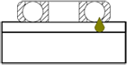
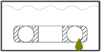
When monitoring your bearing lubrication with ultrasound, it is important to watch for very high values in your condition indicators (total RMS and Peak values). After applying grease, both values should decrease proportionately. This is a sign the bearing was under-lubricated. If the total RMS value lowers and the peak value stays relatively the same, then the bearing has a mechanical condition that is generating impacts.
by Allan Rienstra - SDT Ultrasound Solutions
Comments that I have heard in all types of industry are “We always have the time or money to do the repair over, but never time or money to do it right”. Many times when equipment fails there is an incredible rush to get the machine back online due to some production requirement. This usually leads to repairs that are inadequate or incomplete. It is important to remember that as long as your lock is on the machine it is not going to go back into service until you remove that lock. It could take as little as an additional 30 minutes to allow the machine to be repaired completely, but instead, the job is rushed and a few weeks or a couple of months later the same machine is being repaired for the same reasons again.
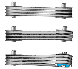
Production controls the purse strings that is a given, but generally, product quality and maintenance cost can be better controlled by allowing for a complete repair, not a partial fix. A couple of examples that come to mind are belt-driven machines. Many repair techs simply roll V-belts on and off for removal or installation. Have you ever noticed a V-belt running upside down? In most cases, it is due to the cords in the backing of the belt being broken. This is usually caused by rolling the belts on or off the sheave. If “power band belts” are used the cost of those belts is usually higher than the sheaves that the belts are running on. It is a paradox that brand new belts will be installed on worn-out sheaves.
When the sheaves are replaced most of the sheaves are affixed to the shaft with a taper lock hub. How many people use an indicator to ensure that the sheaves are square to the shaft and not just tighten the hub with an impact wrench? There are others examples, but hopefully, this drives the point home. Repairs need to be done in a timely fashion in cooperation with production to minimize downtime and reduce any effects on quality.
by Gary James CRL

- Most electrical cabinets are not hermetically sealed. Scan your ultrasound detector around the panel sides and ventholes to detect discharges like arcing, tracking, and corona.
- Not all electrical discharge faults produce heat. Use ultrasound solutions to hear what your infrared camera cannot see.
- Electrical discharge activity is amplified by high humidity. When performing ultrasonic scans at substations make note of the date and weather conditions.
- Ultrasound travels directionally through air compared with an audible sound. When scanning from a distance, therefore, it is important to inspect electrical systems from all sides.
- Corona discharge produces no heat on electrical systems below 240 kV so don’t rely entirely on infrared to find problems.
by Allan Rienstra - SDT Ultrasound Solutions
Reposted from EASY-LASER® blog
- FAST AND ACCURATE
Laser alignment can be done ten times faster and much more accurately compared with dial gauges or straight edge methods (depending on the user’s skill). A dial setup will not measure down to 0.001 mm – but a laser can! - QUICK TO SET UP, EASY TO USE, AND HIGHLY RELIABLE
A laser alignment system is quick to set up, easy to use, and much more reliable than old technology. The latter often requires extensive experience and sometimes complicated calculations to be used. For example, fixtures for dial gauges always sag a little, which affects the accuracy of the gauge’s displayed value. This does not occur with laser alignment. - POSSIBILITY TO GENERATE REPORTS WITH RESULTS
With a laser alignment system, it is possible to generate PDF reports directly from the instrument. The computer handles targets and tolerances and makes it easy to interpret the results. The possibility of documenting the results gives better control over the machines and greater assurance. Reports can be generated for “before” and “after” alignment. - A TRUE REPRESENTATION OF MACHINE FRAME DISTORTION
For soft foot issues, regardless of what is going on at the feet, you get a true representation of the movement between the rotating axes of the shafts you are aligning. Dial readings only tell you what’s happening at the feet—not a true representation of soft foot! - THE SPEED AND PRECISION SAVE YOU MONEY
The speed of use and the precision in alignment mean that investing in a laser-based shaft alignment system usually pays for itself within 3-6 months. - A DISCIPLINED AND REPEATABLE PROCESS
Laser alignment systems make the process of measurement and correction much more disciplined and repeatable. Straightedges and dial gauges are not sufficiently accurate for today’s modern machines. Using laser alignment always gives the same results regardless of who takes the measurements. - EASY TO LEARN AND TO USE
You don’t have to be a specialist to get the correct result. With a wireless display unit, you can follow the machine movement with live values at the points where you adjust the machine, not just where the dial gauges are mounted.
- EXPAND ALIGNMENTS AND MEASUREMENTS
With the best laser alignment systems you can expand the types of alignments and measurements you can do. You will then be able to take care of all important steps of machine setup, for example, base flatness and twist, and also measure straightness. - POSSIBILITY TO MEASURE WITH A SMALL SHAFT ROTATION
With laser alignment, it is possible to measure even with a small shaft rotation, for example only 70 degrees. This solves the problem when piping and machine parts are in the way preventing a greater rotation. - REDUCED ENERGY CONSUMPTION
Laser alignment allows precise measurements that reduce your energy consumption in the long term. Poorly aligned machines require more energy to achieve the same results than well-aligned ones. Reduced energy consumption is not only good for your electricity bill, but of course also for the environment. - ERROR-FREE AND HIGH-RESOLUTION TECHNOLOGY
Old technology may have too low a resolution to measure accurately enough and may be subject to reading errors or sticking dial hands. Laser alignment systems are based on high-resolution non-contact technology and are free from such errors. - ELIMINATION OF HARDWARE SAG AND SETUP MISTAKES
With laser alignment, you eliminate errors associated with old technologies such as bar sag, substandard dial bar, and mistakes when installing up the indicator clamps.
by Ana Maria Delgado, CRL
First and foremost vibration data setups must be properly configured to allow the correct results to be collected thus allowing the analyst to interpret the vibration data for defects. The defect findings should be presented in a manner that the personnel that is responsible for the repair of the equipment now have the necessary information to perform their intended function. The vibration data alone will not fix anything. A vibration database must have the proper setups, the vibration data must be collected correctly using the appropriate instrument, and analyzed by a properly trained and confident analyst. This allows for the root cause of the problem to be found as opposed to only replacing parts. It is very critical that the correct person becomes the vibration analyst. This person should have the desire and drive to become the best that they can become at that position. The analyst should also have support from upper management to allow them to focus on one job.
With the right people, right tools, and support you will have the meaningful data to drive and sustain valuable results and continuous improvement.
by Gary James CRL
Reposted from EASY-LASER® blog
Are you the type of person who, going by the principle of “We’ve always done it this way, and it’s worked well”, continues to use a ruler or a piece of string to align your sheaves/pulleys? If so, you can definitely save some money, by reading this.
It is a common misconception that it doesn’t matter whether you align your pulleys or not. The belt is flexible, and can handle it, right? And if a belt or sheave becomes worn, it is easy to just replace it. But what you might not be considering is that the cost of energy is greater than the cost of buying new spare parts such as bearings, belts and pulleys. Studies have shown that with correct alignment it is possible to improve the efficiency of your belt drive saving you from 5 to 20% of your energy costs. This can quickly add up to significant amounts, particularly if your enterprise has tens or even hundreds of belt-driven machines.
CONSEQUENCES OF GOOD AND POOR BELT ALIGNMENT
Poor alignment or incorrect installation are the most common causes of abnormal wear of sheaves and pulleys. On the other hand, increased productivity, fewer unplanned operational stoppages and reduced energy consumption are the result of well-aligned machines. In the long run, this is also positive for the environment. By aligning your belt-driven machines, you also reduce vibration that harms the machine and adversely affects the working environment.
One consequence of poorly aligned belt drives that is often overlooked is that incorrectly aligned or improperly tensioned belts can result in abnormal temperatures, caused by the belt’s friction against the pulley. Excessively high temperatures will cause the belts to harden, resulting in cracking. A toothed belt can lose teeth, leading to slipping and efficiency loss. Strong heat sources in the vicinity also affect belts negatively. A thermal camera can help to indicate potential abnormal temperatures.
WHERE DO I START?
Many belt manufacturers advocate preventive maintenance in order to avoid unforeseen stoppages. A scheduled operational stoppage is obviously more efficient and less costly than an emergency repair on a failed drive. However, having a maintenance program for your belt drives can also be efficient. There are a number of factors that determine how often you should perform preventive maintenance. Start by classifying your machines in these ways:
- How critical the machines are for your operation.
- The rotational speed of the machine.
- The drive’s impact on the environment.
- The current status of the drive (i.e., condition/quality of the belts and pulleys.)
When you have done this, you will be in a better position to know how to prioritize your maintenance work.
You should also think about the following:
- First and foremost, it is worth thinking about keeping the area around the machine free of dirt and debris, and ensuring that the base is in good condition.
- It is important for the person carrying out the maintenance to have the correct training and equipment to carry out the work satisfactorily. A laser pulley alignment tool is highly recommended.
- Check the machine manufacturer’s specifications regarding how to set up your machine correctly. Write this down so that it is easily accessible the next time maintenance is to be performed. This saves time.
- Check the belt manufacturer’s suggested belt tension values. A spring gauge to measure belt tension is an essential item in the aligner’s toolkit.
- Mixing different belt types or brands is not recommended.
- If the transmission has several belts abreast, all the belts should be replaced together, even if only one is found to be defective.
- Measuring energy consumption before and after alignment is a simple way of verifying that you are now saving money.
- Listen to and look at the machine. If you suspect that anything is abnormal, you should investigate this. You should look out for unusual and abnormal wear or damage.
- Inspections should be performed frequently, perhaps as often as once a month.
- In addition, preventive maintenance should be performed at 6 to 12-month intervals.
- Follow the belt manufacturer’s instructions when replacing belts. Make sure that you also store belts correctly: don’t hang them, coil them flat! (Belts are a perishable product!)
Click here for examples of how much you can save by having your belt drives correctly aligned.
If you are ready to start improving the efficiency of your belts and sheaves, find the tool that best fits your needs.
by Yolanda Lopez
Rotating equipment produces a sound (ultrasonic) signature during operation. This signature can be measured and trended over time. As the machine components begin to fail a change in the ultrasonic signature will occur.
The change in sound level can be used to alarm that could be related to lubrication or bearing damage. A key factor to using an ultrasound tool successfully to determine machine health is collecting the measurements at the same location every time. The first step is to identify a measurement test point for each bearing to be monitored.
One method for data collection is to use a magnet that should be attached to a metal pad epoxied to the measurement location. The use of a magnet and mounting pad will allow for repeatable and consistent data for accurate trending and alarming. If access to measurement locations is restricted, then a sensor can be permanently installed so that measurements can be taken remotely. Ultrasound is an extremely valuable tool that can be used to detect bearing problems with slow-speed applications.
Ultrasound is an important part of any reliability-based condition monitoring program and can provide early warning of mechanical failure. This early warning can lead to reduced downtime and increased plant reliability.
by Dave Leach CRL CMRT CMRP
Strobe lights are an inexpensive tool typically used to determine the operational speed of the equipment. Strobe lights should be readily available to vibration analysts and maintenance mechanics. A strobe can be used as a proactive tool for many things. For example, visual inspection of belt damage (slippage, wear, etc), coupling damage, loose components, and much more can be identified with this handy tool, while the equipment is running. Don’t overlook the value a strobe light can provide beyond just the simple determination of the operational speed of a machine. But keep two things in mind: SAFETY must be first and foremost in your mind at all times when using a strobe light. Since a strobe can appear to “stop motion” on moving components, the temptation to touch the object you are looking at can be strong at times. Avoid this temptation and always stay focused on what you are doing. Also, people prone to epileptic seizures triggered by flashing lights should avoid exposure to a strobe light.
by Trent Phillips CRL CMRP - Novelis
Proper equipment function requires a properly aligned and balanced machine. Allowing a machine to operate with an unbalance condition can result in bearing damage, cracks, loose components, and many other costly maintenance issues. Loose debris can dislodge and impact the balance quality of a machine. Debris buildup on the impellers/blades, and other rotating parts can create unbalance conditions. Before balancing the machine it is very important that the rotating surfaces (blades, etc.) are cleaned of any debris. Removing buildup will help ensure that the machine can be properly balanced and remains in a balanced condition.
by Trent Phillips CRL CMRP - Novelis