Guest Post by Ricky Smith, CRL, CMRP, CMRT
Pipe stress is caused by misalignment of the mating surfaces of two pipe flanges creating abnormal internal stress of pump bearings, seals, motor bearings, and couplings, and can possibly change the displacement of a pump.

General Rules which must be followed by maintenance personnel and contractors: (if you truly want to stop a long term pump problem)
- Pipe flanges attached to pumps must be aligned where the gap does not exceed the thickness of two gaskets or the tolerance established by your company’s engineering standards.
- Pipe flange bolts must drop in without assistance.
- Cable pullers, come-a-longs, or long bars should not be used when aligning a flange that is connected to a pump.
- Validate the elimination of pipe stress by following the guidelines listed below.
Failure Modes experienced from Pipe Stress on Bearings:
- Wear caused by seals leaking
- Wear caused by static vibration
- Indentations caused by overloading while static
- Corrosion caused by inadequate lubrication caused by abnormal loading (seal leaking)
- Flaking caused by misalignment and excessive loading
WARNING: Ensure your contractors follow the same process to eliminate pipe stress. Pipe stress elimination should be validated during the commissioning of a new pump.
Follow this process if you want to inspect your pumps that may have pipe stress:
- Align the two shafts between your pump and driver (typically an electric motor) to the tolerance recommended by the equipment vendor or your company’s engineering standards.
- Validate misalignment to insure motor and pump shafts are aligned to specification.
- Disconnect the outlet flange on the pump.
- Revalidate laser alignment of shafts.
- If alignment has moved then you have pipe stress. Do the same for the inlet flange.
- Make corrections as stated in the following procedures to eliminate pipe stress.
Elimination of Pipe Stress – “The Ricky Smith Method for Pipe Stress” as learned from Dan Turner (his maintenance and engineering manager at Exxon during his career in the 1970s)
- Bolt flanges to pump and insert blind flange gasket along with two regular flanges between pump and mating flanges (cover the hole between the welding area and inside the pump).
- Attached welding ground to flange. (do not attach ground lead to pump; welding group must always be attached to flange) WARNING: Failure to accomplish this one task properly will cause bearing failure by “electric arcing” which is a failure mode of bearings.
- Tack weld flange into place reverse welding each tack.
- Allow cooling for 10 minutes.
- Reverse stitch weld on opposite sides on the flange is similarly used for cast iron welding.
- After initial reverse stitch weld then weld normally using electrode recommended by the American Welding Society (typically E-6010 5P or GTAW)
- After root pass; weld in any direction you wish.
- Allow to cool and then disconnect flange, replace gaskets and;
Validate bolts will drop into holes without a pry bar.
Validate gap between flanges is no more than two gaskets thick.
To learn more about the effects of running equipment with pipe stress, watch the LUDECA Shaft Alignment Know-How Pipe Stress tutorial video.
by Yolanda Lopez
This blog post concerns rolling element bearings and not journal bearings.
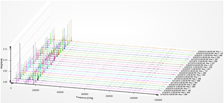
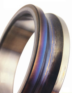 When a rolling element bearing begins to deteriorate the damage usually manifests itself in one of the races (either inner or outer) followed by the rolling element, and finally the cage. When the races begin to have defects these tend to excite the natural frequencies of the race which typically show up beyond the maximum frequency that most analyzers collect data to.
The specific defect frequencies are determined by the bearing geometry. One would normally start seeing peaks in the FFT spectrum in the 5× to 7× range and sideband peaks spaced at 1× rotational speed. As the defects progress, harmonics of the component defect frequency will move lower in the FFT with more harmonics showing, while the number and amplitude of the sidebands increases as well.
When you begin to see the defect frequencies of multiple components, then this indicates that the damage is progressing. In the time-waveform’s early stages you will see an increase in the amplitude of the peaks, indicating impacting; as damage increases the amplitude of the impacts will increase and for a time the pattern will resemble what is known as the “angle fish” pattern. This pattern will not last and may not even be seen depending on the frequency of the data collection. The pattern tends to go away because of continued deterioration of the bearing components.
by Yolanda Lopez
Question: When is it OK to over-lubricate your bearing?
Answer: NEVER!!!!, (almost) the exception is when high vibration exists.
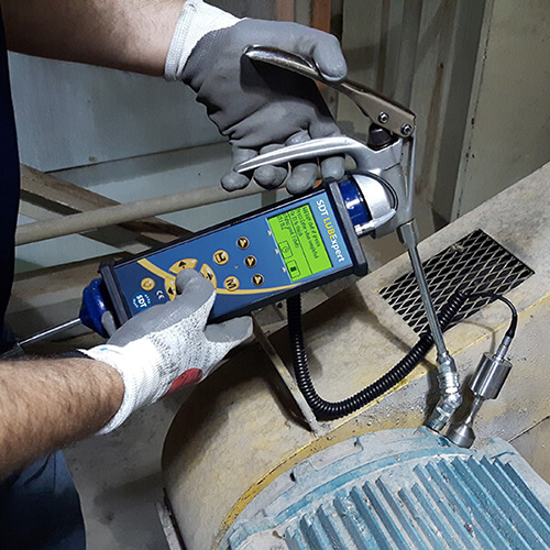
If you attended the SDT/LUDECA Acoustic Lubrication Workshops then you now understand grease as a lubricating mechanism. You understand that the Churning Phase of the lubrication task is inevitable, and long-term, detrimental to the health of the grease. Therefore, we want to move as quickly as possible from the Churning Phase to the Bleeding Phase. This is the natural progression of precision lubrication.
Grease is not a robust grease mechanism. It is actually quite fragile compared to an oil-only system. But we need grease as a lubricating mechanism in bearings because the properties of grease help to keep the lubrication in and around the warzone while sealing out contaminants.
Vibration is inherent in every machine system. Excessive vibration, however, negatively impacts the ability of grease to lubricate. Some machine systems are intentionally vibrated as part of their function and process. Other equipment vibrated excessively because of a defect such as imbalance, misalignment, poor installation, or poor workmanship. For these machines, it might be best practice to over-grease their bearings.
I know that sounds counter to what we teach and know, but consider this. It is better to have thickener and oil in the warzone of the bearing than it is to set up a bleeding mechanism and have the reservoir destroyed because of high vibration. If we let this happen we may never get any oil where it’s needed.
High vibration? Slightly over-grease your bearing and allow a little thickener to exist in the warzone. It is the best compromise.
Download our 5-Step Acoustic Lubrication Procedure.
by Yolanda Lopez
Reposted from People and Processes, written by Jeff Shiver CMRP, CPMM, CRL

The CMRT exam is the leading credentialing program by the Society for Maintenance & Reliability Professionals (SMRP) for the knowledge, skills, and abilities of maintenance and reliability technicians.
The CMRT exam tests competency and knowledge of specific tasks within 4 domains: Maintenance Practices, Preventative and Predictive Maintenance, Troubleshooting and Analysis, and Corrective Maintenance.
And that’s all well and good! But, why should you have your technicians certified? What are the benefits of having them pass the CMRT?
Here are 5 reasons why you should have your technicians certified:
- Validates the individual’s knowledge of maintenance and reliability best practices within the 4 domains.
- Confirms your commitment to advancing your team’s professional development.
- A globally recognized certification provides a personal level of satisfaction and pride in accomplishment.
- Encourages people to move beyond the status quo and achieve more for the organization.
- Determines strengths and opportunities by subject area to provide a development plan roadmap.
Get certified today! Click here to learn more about the CMRT certification.
Learn about People and Processes’ Maintenance and Reliability Technician Core Concepts Course
by Yolanda Lopez
Guest Post by Bob Dunn from I&E Central, Inc.
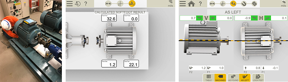
I had the opportunity to use the Easy-Laser XT440 to assist a customer in aligning a machine that had perpetually given them problems, with bearings always running hot. They had recently aligned the machine with dial indicators, but when we checked, it was off by .007, and this was on a 3600 RPM motor. We removed their old shims and did a soft foot check indicating .032 under one of the feet. Further inspection showed an angular gap under one foot. It turns out that when new, someone had ground down the feet on the motor to better align to the pump – obviously not a precision job. We step-shimmed to fill the angular gap, then aligned the machine in a single move. Several of the techniques we used were unfamiliar to these mechanics.
Takeaways:
- Do your pre-alignment homework to detect and correct foundation issues.
- Be sure mechanics are really trained in alignment – not just how to push the buttons. By the way, Ludeca Inc. and I&E Central provide excellent training.
- The Easy-Laser XT-Series is a fast, accurate, and incredibly easy-to-use tool for coupling alignment and more. If you use something else, you should see what you are missing!
by Ana Maria Delgado, CRL
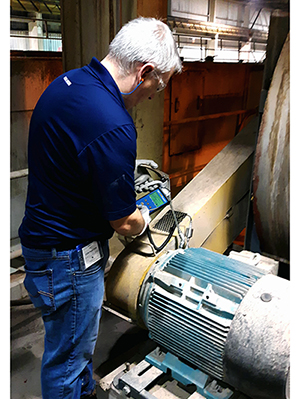
In most cases, when equipment is in failure mode, it begins to make sounds that are not commonly heard during normal operating conditions. Once this sound is heard a defect (at least one) is already present in the equipment.
Using our vibration tools can assist in detecting the defect before that sound is heard with the naked ear.
Think of a vibration sensor as a stethoscope that allows a vibration instrument to listen to the heartbeat of the equipment. The heartbeat is then recorded and data can be viewed historically for that equipment. The data can then be compared to other readings collected on the equipment to quickly see if any changes have occurred.
by Yolanda Lopez
There are 3 techniques that can facilitate your work in the field: the shielding technique, the covering technique, and reflection management.

1. Shielding technique
This technique greatly reduces the influence of interfering leaks. It consists in using a piece of cardboard or foam(*)… to create a barrier between the “parasitic” leak noise and the location where you want to detect/locate a leak.
(*) Any material will work. It will reflect approximately 90% of the energy coming from the interfering leak.
Practical advice: the precision indicator tip placed on the internal or flexible sensor acts as a shield. This technique is very useful when leaks are very close to one another.

2. Covering technique
This technique also greatly reduces the influence of interfering leaks. It consists in:
Either covering an interfering leak with a rag or glove while you inspect an area.
Or covering the sensor with a rag or glove in the zone you want to inspect.
A leaking valve body can be conveniently covered with a cardboard carton too.
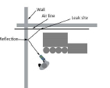
3. Reflection management
When searching for leaks, we sometimes get the impression that a leak is coming from a place where there is clearly no compressed air, such as a wall or a partition. This is due to the phenomenon of reflection. Ultrasounds from the leak are bouncing off the reflective surface. You will find the leak by following the angle of reflection. The angle of reflection is equal to the leak’s angle of origin relative to the reflection surface.
Download SDT Leak Surveyors Handbook to learn more!
by Yolanda Lopez
As Published by Solutions Magazine March/April 2018 issue
by Ana Maria Delgado, CRL and Shon Isenhour, CMRP CAMA CCMP, Founding Partner at Eruditio LLC

During the many root cause analysis (RCA) investigations we facilitate and coach, we notice some themes that continue to manifest themselves in the findings. Often, they are grouped under the heading of precision maintenance or lack thereof. Let’s take a look at some of them and determine if they are also killing your reliability.
The six killers are grouped into three areas: Lubrication, Misalignment, and Undiagnosed Wear.
Click here to read the full article.
by Ana Maria Delgado, CRL
1. A Change in the Quantity of Grease Consumed
Maintenance departments track their grease consumption to monitor and control costs. A change in consumption is a sure sign that your lubrication program is on the right track. Most organizations are guilty of over-lubricating. Expect lower grease consumption as your program matures. Bad procedures lead to bearings routinely receiving more grease than they’re designed to handle. The excess ends up being pushed into the motor casing or purged onto the floor.
Over lubrication happens when re-greasing intervals are scheduled based on time instead of condition. Control lubrication tasks with ultrasound to monitor the condition and maintain optimal friction. The time between greasing intervals increases, resulting in less grease used per bearing.
2. Fewer Lube-Related Failures
Do you track failures and perform root cause analysis?
Organizations with optimized greasing programs experience fewer lube-related failures. Less fixing and fire-fighting translates to more creative time for maintenance. Use that time to bring more machines into the greasing program.
Additionally, with ultrasound, you find many non-trendable defects. For example, broken or blocked grease pipes and incorrectly fitted grease paths prevent grease from reaching the bearing.
3. Optimized MRO Spares Management
Your new and improved lubrication program is delivering wins; better control of grease consumption, fewer failures, and more productivity for maintenance. Use this time to study trends and better manage your storeroom.
A decrease in bearing-related failures improves spares optimization. Share your ultrasonic lubrication data with your MRO Stores manager to create a plan to reduce the number of emergency parts on hand.
Since you’re taking stock, why not shift some burden to your suppliers? Ask them to confirm your emergency parts against their own stock. If it can be supplied on the same day then it doesn’t need to be on the balance sheet.
4. Increased Number of Machines Monitored
One benefit of an effective lubrication program is time.
• Time allotted to monitoring machines instead of fixing them.
• Time allotted to correctly assessing the real needs for lubrication.
• Time to look at the big picture.
Take, for instance, criticality assessment. Many lubrication programs begin with small steps. All the “A” critical machines receive priority, and rightly so. But what about the rest? With more time to plan, organize, and schedule, the number of machines acoustically monitored for optimal lubrication increases.
5. Save Time. Combine Acoustic Lubrication and Condition Monitoring
You worked hard for these results. It’s time to use your data for more than just lubrication.
Acoustic lubrication is the proven method to ensure precise bearing lubrication. New technology from SDT, LUBExpert, combines the power of onboard lubrication guidance with Four Condition Indicators for bearing condition assessment.
The time savings from assessing bearing condition during the lubrication process is beyond valuable and another sign your acoustic lubrication program is on the right track.
6. Inspector Confidence at an All-Time High
Reliable machines are the product of an effective lubrication program. You have:
• Managed grease consumption
• Fewer grease related to bearing failures
• Optimized MRO spares
• More machines under watch
• Increased data collection intervals
The power of adding ultrasound to your greasing program delivers win after win for reliability. Reliability breeds confidence. More confident inspectors making the right calls and infecting a positive culture throughout the organization.
by Allan Rienstra - SDT Ultrasound Solutions
In the 35+ years of experience that LUDECA has in shaft alignment, we have been asked this question many times. How long does it take to do an alignment? People in charge of scheduling have a tough task when allotting time for technicians to do an alignment with precision. In many cases, they may just take a guess, based on the average time it has taken in the past. The answer is not so simple. During a one-day seminar, I had to perform an alignment on a motor to a pump to show the proper steps when aligning a machine. When the time came to start the alignment, all the safety procedures had been taken care of, and the machine had been rough aligned. The soft foot values were within tolerances. So I was able to align the machine in under 45 minutes, within the tolerances specified for 1200 RPM.
On another occasion, I was hired to help align a generator to a turbine. Quite a few things went right as well. The safety procedures had been taken care of by the time I got there. The coupling guard and coupling element had been removed. The machine had also been rough aligned. The special-order shims for the generator feet were available on-site. Even with all these things going my way, this alignment took a day and a half to finish. There are things that come up during an alignment that cannot be planned for. One of them is a soft foot condition. Not checking for soft foot can greatly increase the time it takes to align a machine, mainly because the response to corrections stipulated by your alignment tool will not be accurate. Therefore, knowing the soft foot condition and minimizing it, is key. However, that in itself can take up a long time, depending on the condition of the baseplate, the condition of the anchor bolts, washer, pipe stress, etc.
In both cases, they were a single coupling alignment. Aligning a large generator is obviously more difficult than a 200HP motor. In the first case, I was able to turn the motor with a strap wrench by myself. In the case of the generator, it needed to be uncoupled because the two machines could not be turned together. In most cases, a larger machine takes longer to align because breaking the bolts loose, alone, could take 20 to 30 minutes. Furthermore, there can be a large difference in the amount of time it takes to finish an alignment, between two identical machine sets. The information obtained here can help reduce the alignment time.
I recommend downloading our 5-Step Shaft Alignment Procedure and/or requesting our Shaft Alignment Fundamentals Wallchart for your alignment team. The point is that there is no fixed amount of time required for an alignment of a machine. If a scheduler should err, it should always be on the conservative side.
by Adam Stredel CRL
Just what does it take to be successful at balancing? Let’s start with some basics. First, you need to have an understanding of the balancing process, next nomenclature: is it unbalance, imbalance, out of balance, or what?
Use a consistent description and stick with it. Next, think about what the source of unbalance could be: is it uneven wear on parts? Voids within castings? Damage from impacting? Material buildup? Even though buildup is not usually a problem, when it begins to come off it rarely does so evenly thus creating an unbalance. In other words, unbalance is simply the uneven distribution of mass.
Simply review or collect data to ensure that the undesirable vibration is from unbalance and not some other issue such as a belt problem, misalignment, electrical issue, etc. Once you’ve determined that the vibration is indeed unbalanced you need to inspect the object to be balanced. If it is not clean, clean it. Look for damaged or broken parts. On belt-driven equipment inspect the belts as their frequency can be very close to running speed and can hinder the balance job. Make sure you have the proper tools for doing the balancing job, such as a balancing instrument capable of reading the vibration that is produced at running speed or what is commonly referred to as 1×or 1 times and capable of indicating the phase angle at 1×. This could involve utilizing an optical tachometer, laser tachometer, magnetic pickup or even a stroboscope. Some tachometers will require a piece of reflective tape on the shaft for the tachometer to read from and this might require stopping the machine if still in service.
Tip: I try to place the tape horizontally, or along the axis of the shaft, with the leading edge of the tape on the trailing edge of the keyway. This can be helpful if you ever have to return for another balancing job on the same machine. You need to determine if you will be adding or removing material in order to balance the rotating component. If removing material, how will you determine how much you’ve removed; if adding weight, you need to make sure the weight you are adding is of a material that is compatible with the service the machine is exposed to. If adding material “weights”, how will they be attached? With set screws? Bolts? Clamps? Welded on? All this should be considered. One last tip: if after two runs you’re not there or almost there yet, you might need to stop and examine your process to ensure no mistakes have been made.
Download LUDECA’s 5-Step Balancing Procedure.
by Gary James CRL
1. Collect the best data you can, using a high-quality ultrasonic data collector.
2. Consistent sensor placement must fundamentally be observed.
3. Identifying boundaries that impact data transmission is imperative.
Ultrasound is Shy… It Keeps Boundaries
Think of ultrasound as the quiet introvert. It prefers to stay in, and rarely mixes well with ultrasounds from other places. We call this “boundary behaviour” and it’s another characteristic that makes ultrasound such an attractive condition monitoring technology. Ultrasound signals remain isolated to their source, making it easy to pinpoint defects without interference from other elements of the machine.
Sensor Placement
Inspectors tempted to place their ultrasound sensor directly on the gearbox cover should reconsider. This common mistake affects data integrity. A gasket seals the cover plate to the gearbox housing. The specific acoustic impedance of the gasket material differs greatly from the cast metal of the gearbox. The change in materials a boundary barrier through which bashful ultrasound is reluctant to be passed. A better option is to place the sensor on a bolt head, which is directly connected to the gearbox housing. The result is crystal clear ultrasound signals for listening, trending, and condition assessment. HearMore: Click here to listen to Damaged Gearbox.
Special thanks to our partner Allan Rienstra from SDT Ultrasound Solutions for sharing his great knowledge with us!
by Allan Rienstra - SDT Ultrasound Solutions
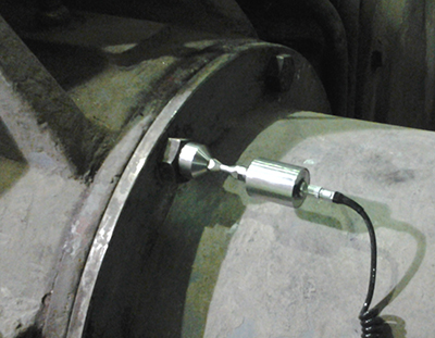
With the proliferation of online monitoring systems utilizing permanently mounted sensors, users will need to beware of “direction sensitive” vibration and possible sudden unexpected failure due to insufficient data. The thought of insufficient data may seem incredible when thinking of constantly monitored equipment, but consider the all too common (IMHO) practice of uni-directional (one direction) monitoring of machine trains.
Many installations, due to initial cost, are mounting a single vibration sensor at each bearing. While this may be sufficient for most equipment trains, most of the time, it will certainly not be sufficient for all equipment trains all of the time. Although I don’t have hard data available, if I were to make a statement based on personal experience, and anecdotal evidence from other practitioners, my statement would be something like this: “80% of horizontal equipment could be pretty well monitored by sensors mounted at the horizontal radial position on each bearing.” I say pretty well monitored because I just can’t bring myself (as an analyst) to be completely satisfied without the vertical and axial data.
This setup would catch virtually all unbalance and roller bearing faults (excluding thrust bearings), some to most misalignment faults, and a sprinkling of others. I use the word “catch”, to mean it would give an indication of a developing problem. Accurate diagnosis of unbalance, misalignment, bent shaft, and even looseness in many cases (as well as a host of other possible faults) would require more data.
If the online vibration program manager takes these facts into account and governs the program accordingly, they should be pretty successful. If they add to the online program a “full battery” vibration survey, maybe semi-annually, just to catch the less common, but possibly very destructive defects that could develop undetected by the uni-directional monitoring, they would most likely be very successful.
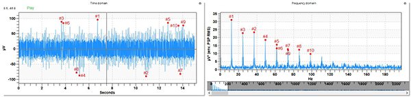
What could be so destructive and yet be completely undetected by the uni-directional sensors? The Big R for one is Resonance. Resonance is often extremely directional. Consider a case history LUDECA co-published with one of our customers in the December 2012 Wastewater Processing magazine:
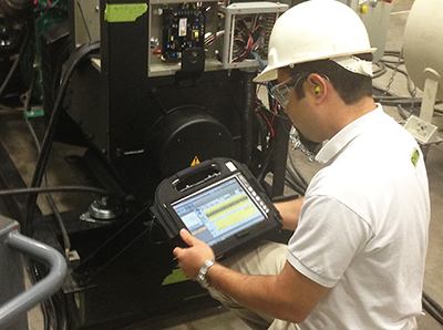
In the table below (Figure 1), the 1× amplitudes are displayed. I have hidden all but the vertical data, as though it were monitored only by vertical sensors.
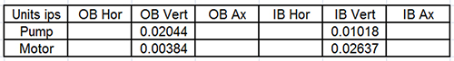
Everything is wonderful right? Look at the motor outboard vertical, only 0.00384 inches per second—very impressive. Of course, at this point you are thinking “he is setting me up for something” and you are correct. Even though most anyone would love to have these amplitudes on virtually any machine, this particular machine was tearing itself apart with vibration!
We will give the reader a little more data, just to help add emphasis to the directional nature of resonance. We will add the axial data to our table in Figure 2:
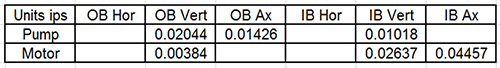
Still very, very good… so far. Now, look at Figure 3, with the addition of the horizontal data.
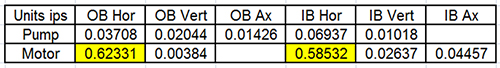
The motor outboard horizontal amplitude is 162 times the amplitude of the motor outboard vertical! What if the user had only vertically mounted sensors? What about vertical with the added information of axial? You may be thinking “if I had only horizontal sensors, I would have been ok”, and for sure you would have been better off than having only vertical. You would at least have known you had a problem, but you would not have known what that problem actually was. You would likely have assumed the vertical and axial are probably vibrating badly too.
Hopefully, you would have verified the vibration in the other directions. As it was, the user had data from all directions and a simple glance told the analyst with a high degree of confidence what the problem was. Resonance is almost alone in creating that kind of directional disparity.
To reiterate, the online vibration program manager should be successful if they take into account the fact of limited data and supplement the online program with a “full battery” vibration survey at a cost-effective interval, just to catch the less common, but possibly very destructive defects that could be developing undetected by uni-directional monitoring.
by Mike Fitch CRL
While the person in charge of collecting vibration data is actually collecting the data, they should watch the data “live” for unusually high amplitudes or discontinuities in the data. This will not increase the data collection time, and if any of these issues are detected, the person can evaluate whether or not the data is “good” or not; if not, the data can be recollected, or if it is “good” then additional data may need to be collected to ensure that proper analysis can be performed on the equipment. Field notes can be made about the machine’s condition and its status.
If the machine condition is determined to require attention, the analyst might need to contact someone at the facility. Remember that sudden increases or decreases are usually a sign of machine problems. Looking at or analyzing the data in the field can give the analyst a good idea of what issues need to be analyzed, thereby reducing the time to analyze data in the office. If not analyzing the data on the spot, one can at least make notes to aid in later analysis.
by Gary James CRL
♫ And it’s too late baby now, it’s too late; though we really did try to make it. Something inside has died and I can’t hide and I just can’t fake it…♫
So go some of the lines of the old Carole King hit from 1971. Unfortunately, that pretty well sums up the situation for those sad contemporary souls who have computer crashes but didn’t have their databases backed up on a regular, frequent basis. The part about “I just can’t fake it” is especially true after “Something inside has died” (that is, inside of the computer). When you lose your database or databases, there’s just no faking it.
If you are like most, you get a sick feeling inside just thinking about it, and you resolve to get started soon by making a habit of backing it all up. Procrastinate no longer, friend. Get help from your I.T. department, or if you don’t have one, there are numerous players now, that for a small fee, will back up and protect your important data, either locally or in the cloud.
Don’t wait until you are singing the old Carole King song, “It’s Too Late”. Go ahead and protect yourself.
by Trent Phillips CRL CMRP - Novelis
How many facilities only collect vibration data when it doesn’t interfere with other activities? So often collecting and analyzing data is only one part of a given person’s responsibilities and workloads dictate that the collection and/or analysis take a back seat. When this happens, machine problems are not detected and therefore not reported for corrective action to be taken. If a machine then fails management has all the right to ask why the problem was not found and reported, even if management itself is the reason the data was not collected or analyzed! Vibration data collected should also be analyzed in a timely manner (within two business days of collection) to allow for proper scheduling of any needed repairs; of course, if problems are detected while collecting data that are believed to be severe enough to merit immediate attention, then they should be reported immediately to the facility. Many analysts do not know how long it will take to approve, plan, order parts, kit out, and schedule the resources to execute the repair work. Therefore, one must collect, analyze, and report the data as soon as possible. Generally, you may find several problems in most facilities; however, if you hand in 20 or 30 reports to the Reliability contact, they can quickly be overloaded. I would collate and deliver all the necessary reports but would focus on the top 5 priority problems first, based on safety, criticality, severity, and production demand.
by Trent Phillips CRL CMRP - Novelis
Condition Monitoring Expert Tip #9 by Mobius Institute
No, sadly, that may not be correct. If the spectrum (and phase readings) indicate misalignment, then the machine will be misaligned. But if there is no indication of misalignment, the machine may still be misaligned. I know that may not make sense, but unfortunately, it is true.
A number of experiments have been performed where real machines were misaligned and the vibration pattern did not change. The vibration pattern depended upon the type of coupling and other conditions, but the bottom line is that the only way you can be sure that the machine is precision aligned is to precision align the machine with a laser alignment tool.
We appreciate Mobius Institute for allowing us to share this tip with you!
by Ana Maria Delgado, CRL
Using ultrasound to locate compressed gas leaks is relatively easy, but occasionally it can present some challenges. The reason ultrasound is so successful is that it is a high frequency, a short-wavelength signal that does not like to penetrate 2nd mediums. While performing compressed gas leak inspections, keep in mind that strong ultrasonic signals can bounce off most materials leading to false indications.
To overcome this challenge, turn your ultrasonic detector 180° and see if the signal is stronger coming from that direction.
Download Find-and-Fix Leaks Procedure

by Paul Klimuc CRL - SDT Ultrasound Solutions
Condition Monitoring Expert Tip #7 by Mobius Institute
Spectrum analysis provides a great deal of information about the health of rotating machinery. But you should consider the spectrum as a summary of the vibration within the machine.
The Fast Fourier Transform takes the time waveform and computes how much of each frequency is present and displays that as a line in the spectrum (grossly summarized, but that is basically the case). Therefore, if the vibration from the machine is generated by smooth periodic motion, then the spectrum provides a very good representation of what is happening inside the machine. But as damaged gears mesh together, and rolling elements pass over damaged areas on the raceway of the bearing, and as the pump vanes push through the fluid causing turbulence or cavitation, the vibration generated is not smooth and periodic. And there are a lot of other fault conditions that likewise do not generate smooth and periodic vibration. Thus, the only way to really understand what is happening inside the machine is to study the time waveform.
The time waveform is a record of exactly what happened from moment to moment as the shaft turns, the gears mesh, the vanes pass through fluid, and the rolling elements roll around the bearing. Each minute change that results from impacts, rubs, scrapes, rattles, surges, and so much more is recorded in the time waveform and then summarized in the spectrum. Therefore, it is critical to record the time waveform correctly and analyze it when you have any suspicion that a fault condition exists.
Special thanks to Mobius Institute for letting us share this condition monitoring expert tip with you!
by Ana Maria Delgado, CRL
Belt alignment is extremely important, and we recommend you do it with a good laser alignment system such as the Easy-Laser XT190 or the DotLine Laser system.

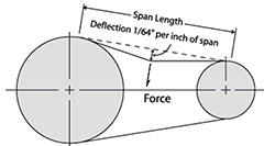
But, once the pulley alignment is done, equally important is to set the belts to the proper tension. Typically, the correct tension is one that allows the belt to be deflected on its tight side by a specified amount of force to an amount of 1/64th inch per inch of span length. The span length is the distance between the nearest points of contact of the belts on their sheaves. If this distance is not known, you can use the center distance between the pulleys; that’ll be close enough.
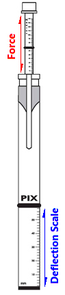
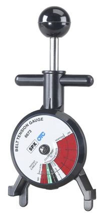
To do this, you use a spring tension gauge, which is a device that measures the amount of force that you apply to something when you push against it or pull on it.
So, say the span length of a given belt drive is 36 inches. You should deflect the belt (in a group of belts, usually the center one, but measure the two outside ones as well) by 36/64″, (or 9/16″) which is 1/64″ of deflection for every inch of span length, and measure how many pounds or newtons of force it takes to do that. This force should not be less (too loose) or more (too tight) than what the manufacturer of the belts recommends for that drive or for that set of belts. Also, you perform this test by pressing down with your gauge upon the belts in the middle of their span length on the “tight side” of the belts. The tight side of the belts is the side that is stretched as the drive turns and the driver pulley applies rotational force to the driven pulley. The return side is the slack side of the belts.
The recommended belt tension deflection forces are usually supplied in a table that takes into account the size, length, and type of belts, the number of belts in the drive, the anticipated application loads and drive ratios of the sheaves. Move the driver until the recommended force specification is met for the desired deflection, being careful not to mess up the sheave alignment while doing so!
Download 5-Step Sheave/Pulley Alignment Procedure
by Alan Luedeking CRL CMRP