Guest post by Bob Dunn at I&E Central, Inc.
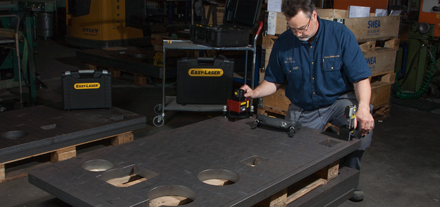
I was working with a customer to align sheaves using their Easy-Laser E180 sheave alignment tool. This is a new blower that had been installed by a contractor. Obviously, the contractor did not check alignment before drilling the mounting holes. The horizontal angular error was about 1.25 degrees and required a move of about 1/4″ more than was available given the placement of the bolt holes. Thanks to the digital measurement of the E180, they knew exactly what correction was needed at the feet to align this machine.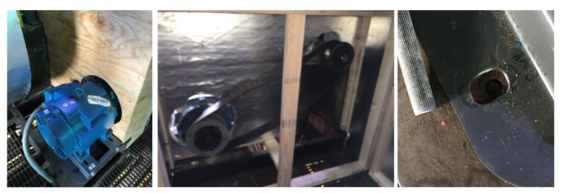
Unfortunately, the solution will be to drill out the holes in the base, then complete the sheave alignment. What should have been a 30-minute job now becomes a much larger project – time and money wasted. My guess is that the contractor checked alignment with a string (or maybe not), which did not get him close enough. Using the right sheave alignment tool makes a difference.
Thanks to Bob Dunn for sharing this case study with us!
by Yolanda Lopez
Guest post by Brandon Weil, CMRP at Eruditio LLC
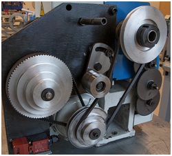
Belts, chains, and sprockets, chances are you have at least one if not all of these in your facility and chances are you’re relying heavily on experience and judgment instead of quantitative inspection criteria. All too often the importance of proper inspection techniques and defined replacement criteria for these critical parts are overlooked. Don’t believe me? Just pull up some of your PM inspection procedures, discuss the topic at a toolbox meeting, or observe someone performing the inspection, you might be surprised at the range of answers and opinions. If there isn’t a specific measurement or min/max criteria, then you’re leaving the inspection up to chance. Another thing to consider is if these parts aren’t being installed properly in the first place you will undoubtedly see premature failures and reduced operational life. Precision maintenance installation tools such as laser alignment for shafts, pulleys, and chains make a world of difference in preventing the introduction of infant mortality-related failures like premature bearing failures, belt and pulley wear, etc.
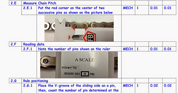
The good news is that you can start improving the quality of your preventative maintenance inspections almost immediately; all you need are a few basic low-cost tools [Click Here] and you will find a document with inspection criteria for these three parts to get you started. Improving your PM inspection procedure, putting the right tools in the right hands, and setting quantitative standards for your inspection is a very low-cost high-return activity that can start paying dividends today.
Download Belt & Chain Storage Best Practices
by Ana Maria Delgado, CRL
I have had the opportunity to see, first hand, the improvement in the quality of alignments our Tradesmen have been able to achieve and I attribute it to the availability of the wall charts received from LUDECA as the main reason. There isn’t much that the charts don’t cover but, it’s the references to thermal growth and the causes of lack of repeatability and response to corrections made that are the most helpful at least for us. As the Vibration Analyst onsite it’s been a win-win!!! Thanks from all of us at Cameco – Cigar Lake Operation —Ben Harrison, Reliability Technologist
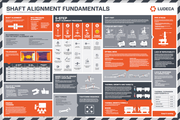
Request your copy of the LUDECA Shaft Alignment Fundamentals wall chart
by Ana Maria Delgado, CRL
Reposted from Easy-Laser®
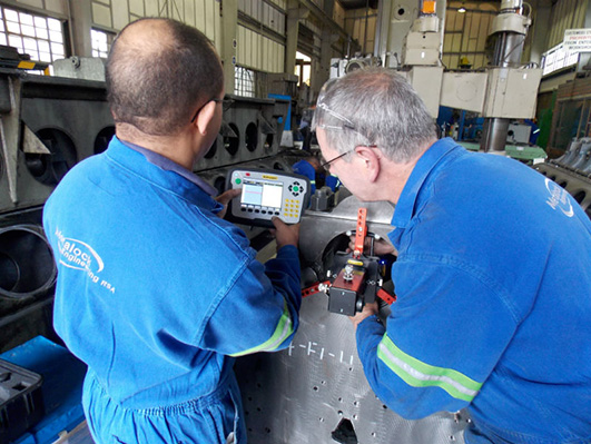
We had a little chat with Eskil Norberg at the company Maskincentrum, who has many years of experience in measuring and aligning machine tools for the manufacturing industry in Sweden.
Because you must be able to predict the level of precision you can achieve for manufactured parts, especially when it comes to large and complicated items, items that can be tough to measure, and also costly to recover if anything goes wrong.
We always start with a thorough analysis of the problem and then continue by choosing the best method and instruments for the specific job.
That depends on each individual problem I would say. Normally we guarantee that we can identify the problem, and then present a solution for how to bring the machine to a level where it can produce within tolerance again.
As I said, that depends on the problem, but for example an electronic precision level for leveling, an interferometer laser for distance, speed, pitch, and yaw measurements. Then a double ball bar for circular interpolation according to ISO 230-4. Easy-Laser® E940 is used for straightness, angles, and spindle pointing direction. It has wireless communication which is very convenient and safe for us because the machine can be run with all safety guards on. The system also provides a measurement report directly on site thanks to the built-in documentation possibilities. This is highly appreciated by the client. Then we also use vibration analyzers to check for unbalances, bearing failures, and sprocket damages.
Of course. Recently when we aligned with our Easy-Laser® on a machine for the manufacturing of steel beams 6 to 12 meters long [20 to 40 feet] we improved the accuracy of the parts from near rejection, i.e. 100% of the tolerance range, down to 10 to 15% of the tolerance range.
First, you must understand the effects that follow the different error conditions in the machine and how they affect the finished products. Always start from the ground up when adjusting the machine, followed by adjustments dependent on previous adjustments. What I try to say is you must adjust in the right order. You should also be aware of how possible electronic compensations affect the machine and its measurement result, so these don’t make the problem worse or maybe disguise any mechanical problem. So, always start from the ground up with the geometry of the machine, that’s my advice. To measure is to know!
by Ana Maria Delgado, CRL
Reposted from EASY-LASER® blog
EMBA Machinery is a Swedish manufacturer of converting machines for the corrugated board industry. They acquired a measurement system from Easy-Laser® in 2015. Their machines can be found within the packaging industry all over the world. Thanks to their reliable function, short set-up time and high manufacturing speed, EMBA’s machines are renowned for high productivity and product quality.
WHAT DO EMBA’S MACHINES DO?
Stefan Stålhandske, Production technician at EMBA Machinery, answers:
To put it simply, they supply a sheet of corrugated board with flex-o-graphic printing, before creating slots, punching, gluing, and folding the sheet to produce a flat box. The final packaging has to be of the very best quality, as it is often the first thing you see when you purchase goods. The quality demands mean that the packaging also has to be strong, i.e. the corrugated board has to retain its strength through the conversion process. It must protect the packaged product during transport and handling, and it has to be stackable. It must be able to be produced quickly, and changing over the machines to a different format must also take place rapidly. Some of EMBA’s machine models produce up to 440 sheets per minute. Try to picture that!
THERE ARE STRINGENT DEMANDS REGARDING PRODUCT QUALITY, MACHINE AVAILABILITY, AND MANUFACTURING SPEED. HOW DOES THIS INFLUENCE THE IMPORTANCE OF THE MACHINES’ QUALITY?
The machines are made up of many mechanical parts, both fixed and moving parts in the form of linear guides and rotating components. Many parts are dependent on one another. EMBA places stringent demands on itself and its suppliers. A separate measurement department checks machined components. Installation procedures are based on combined experience as well as generally applied requirements and tolerances. Many machine parts were previously manufactured in our own production premises in Örebro, which entailed a very high level of control of manufactured components and traceability to the machines in which they were produced. We now have a number of suppliers who have to manufacture to the same high level of accuracy, which has meant that we have been forced to develop new procedures and find new control tools.
WHY WAS THE DECISION TAKEN TO ACQUIRE LASER INSTRUMENTS?
The equipment was principally procured in order to quality-assure and guarantee that all machine units are installed correctly with regard to the alignment of the stands hole center to hole center, as well as with regard to their squareness and parallelism. Previous measurement methods such as cross-measurement and measurement using specially manufactured tools must be replaced to achieve a better method of handling and documenting measurement results. We also considered that the equipment can provide us with the possibility in the future of measuring the entire machine line. Many of the machine components are large and heavy and require a mobile measurement system.
WHY DID YOU CHOOSE EASY-LASER®?
EMBA’s development department got to know the product at an earlier meeting at an industrial fair. The way we were received by Easy-Laser®, along with the versatility the instruments have to offer, made it an easy decision, I would say.

YOU MENTIONED VERSATILITY – WHAT MEASUREMENTS DO YOU CARRY OUT?
Flatness measurements on large, heavy components, as well as straightness measurements on long beams with linear guides. During installation, we align machine ends with the aid of hole centering/shaft alignment. We also measure straightness and squareness at this time, as well as parallelism between various linear movements. These measurements are performed with an E720 shaft/geo system supplemented with brackets. To measure parallelism between rolls, we have opted to supplement the system with the E975 Roll alignment kit. The instruments have also been used to perform measurements in machine tools and in order to check that diabase surface plates are level. So yes, versatility really is the right word.
HOW HAS KNOWLEDGE OF HOW TO USE THE INSTRUMENTS BEEN SECURED?
The software is user-friendly, but many of the users have never operated this type of equipment before. As a result, two training sessions have been conducted with Easy-Laser®, lasting a total of 4 days. The training has been conducted at EMBA’s premises, in machines under construction. The training, which intersperses theory with practical exercises, was divided up such that the participants began with basic geometrical measurements and hole centering in the first session. During the second session, the focus was on E975 and measurement of roll parallelism, as well as functionality checking of detectors and leveling of laser transmitters.
HOW WERE THE MEASUREMENTS PERFORMED BEFORE AND WHAT ADDED VALUE DOES EASY-LASER PROVIDE?
In some of the measurements, we have replaced devices and dial indicators. The measurements are performed more rapidly using the laser instrument, and if you are unsure of measurement data, it is easy to repeat the measurement. Above all, however, the measurements are more reliable. For example, we have linear guides installed on beams that have to move in parallel with other linear guides installed on other beams. When we measured these before using dial indicators, we were unable to capture local deviations in the same way as now.
Our laser instrument now gives us the opportunity to pinpoint these deviations as well.
In some cases, earlier measurement procedures have been replaced so that we now measure the machine from different positions instead, which are more relevant for the machine’s conditions. Some measurements have not been conducted previously. The fact that we can now perform these measurements provides us with a basis for discussions with our suppliers and contributes to our work of consistently improving our quality.
EMBA NOW USES THE ROLL ALIGNMENT KIT E975 TO MEASURE THAT THE ROLLS ARE PARALLEL WITH EACH OTHER. WHAT HAPPENS IF THEY ARE NOT PARALLEL?
Some of the most critical rolls are located in the printers. If the rolls are not correctly aligned, this can result in the print being positioned incorrectly on the package, which is unacceptable. If the feeder table is not aligned with the machine line, this results in a crooked printed image, slanting slots, slanting punching, and a folding result that is outside of the stipulated tolerances, all of which are also entirely unacceptable. As EMBA’s machines are renowned for their good range of formats as well as their high machine speed, the machine alignment from unit level to the overall machine line is an important aspect in achieving a good end result, i.e. a perfect box.
HOW WAS ROLL PARALLELISM CHECKED PREVIOUSLY AND WHAT IS THE ADVANTAGE OF E975?
When building units, we relied on the cross-measurement method as well as level with the aid of a precision level. The cross-measurement method is difficult, as access to reference points can be difficult or non-existent. When installing machines, we rely on specially manufactured spacers between the units in order to achieve parallelism as well as precision levels for leveling. Where possible, we can use tape measures to take measurements covering two separate rolls. With the laser instrument, we have the potential to measure all or parts of the machine, in order subsequently to monitor any adjustment of rolls in “live” mode.
DURING SHIPPING, YOUR MACHINES ARE SPLIT INTO SMALLER UNITS IN CONTAINERS AND ARE REASSEMBLED ON-SITE ON THE CUSTOMER’S PREMISES. THIS MUST PLACE GREAT DEMANDS ON YOUR TECHNICIANS?
Absolutely! Prior to handing over to the customer, we perform tests in accordance with a special test protocol. The tests are performed under production-like conditions, for example with measurements being taken regarding register variations in the positioning of printing, slots, and punches. The position of printing, slots, and punches must be able to be repeated within the tolerances, regardless of machine speed. In the future, new measurement methods with the aid of the newly acquired laser instrument will ensure better control of the machine set-up, which ought to generate a faster and safer start-up of production in the EMBA machine.
Thank you Stefan for giving us the opportunity to hear how you use Easy-Laser®!
by Yolanda Lopez
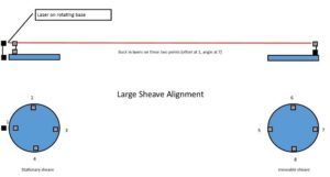
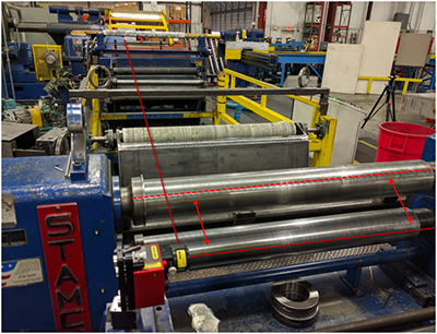
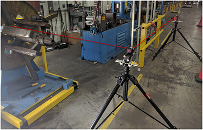
Early last year Bob Dunn with I&E Central, Inc. was approached by a customer with a unique measurement challenge. They needed to align two sheaves, 1 meter in diameter, separated by 12 meters (about 40 feet). While there are a number of sheave alignment tools available in the market, they employ line lasers, and their maximum distances are about 10 feet. Beyond that, for this application, there were physical barriers to projecting a beam right along the face or between the pulleys, so this required some application development.
They discussed with an associate and conceived a way to make this measurement using the standard detectors and programs on the Easy-Laser® E710 alignment system. The E710 is a high-end shaft alignment system with point (rather than line) lasers and 2-axis detectors with a working distance of up to 20 meters (66 feet). It also includes some basic geometric programs including straightness.
The customer’s goal was to align the sheaves in both planes, “horizontal” and “vertical”, within 0.1°. Going back to college trigonometry, 0.1° expressed as a slope is 1.745 mils/inch or 1.745 mm/meter. We can easily measure and calculate that.
The two sheaves were vertically oriented on a long superstructure with beams and supports extending about 10” out from the faces of the sheaves.
Here is how they made the measurement:
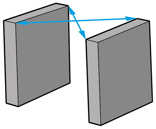
They mounted one of the laser heads (the “transmitter”) on a magnetic base with a rotating head. This magnetic base was mounted on the superstructure of the machine near the centerline of the stationary sheave, and aimed along the centerline. (See the graphic associated with this document.) The detectors themselves were extended from the magnetic bases with pairs of 12″ rods so that we had a clear measurement line along the structure.
They bucked in our transmitter between points 1 and 7 (see graphic). We did not need to set it to zero, we only needed the beam to hit the detector along the length of the measurement. Once bucked in, we used the straightness program and measured at points 1, 3, 5, and 7. Using points 1 and 3 as our reference line, the result indicated that the two sheaves were horizontally parallel within 0.05°, but were offset by about ½”.
Next, they measured the vertical alignment. Without moving the laser transmitter, they swept the rotating head and measured the slope from point 2 to 4, as 6.028 mm/meter. Then they performed the same measurement between points 6 and 8 (the far sheave), measuring 6.022 mm/meter – nearly perfect alignment (0.0003°).
The E710 proved to be a flexible and powerful tool that can do much more than coupling alignment. This new customer is already identifying additional measurements for their new system.
by Ana Maria Delgado, CRL
Reposted from EASY-LASER® blog
- FAST AND ACCURATE
Laser alignment can be done ten times faster and much more accurately compared with dial gauges or straight edge methods (depending on the user’s skill). A dial setup will not measure down to 0.001 mm – but a laser can! - QUICK TO SET UP, EASY TO USE, AND HIGHLY RELIABLE
A laser alignment system is quick to set up, easy to use, and much more reliable than old technology. The latter often requires extensive experience and sometimes complicated calculations to be used. For example, fixtures for dial gauges always sag a little, which affects the accuracy of the gauge’s displayed value. This does not occur with laser alignment. - POSSIBILITY TO GENERATE REPORTS WITH RESULTS
With a laser alignment system, it is possible to generate PDF reports directly from the instrument. The computer handles targets and tolerances and makes it easy to interpret the results. The possibility of documenting the results gives better control over the machines and greater assurance. Reports can be generated for “before” and “after” alignment. - A TRUE REPRESENTATION OF MACHINE FRAME DISTORTION
For soft foot issues, regardless of what is going on at the feet, you get a true representation of the movement between the rotating axes of the shafts you are aligning. Dial readings only tell you what’s happening at the feet—not a true representation of soft foot! - THE SPEED AND PRECISION SAVE YOU MONEY
The speed of use and the precision in alignment mean that investing in a laser-based shaft alignment system usually pays for itself within 3-6 months. - A DISCIPLINED AND REPEATABLE PROCESS
Laser alignment systems make the process of measurement and correction much more disciplined and repeatable. Straightedges and dial gauges are not sufficiently accurate for today’s modern machines. Using laser alignment always gives the same results regardless of who takes the measurements. - EASY TO LEARN AND TO USE
You don’t have to be a specialist to get the correct result. With a wireless display unit, you can follow the machine movement with live values at the points where you adjust the machine, not just where the dial gauges are mounted.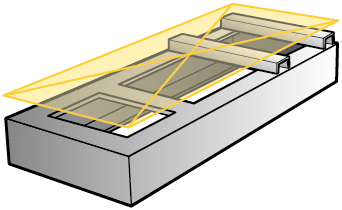
- EXPAND ALIGNMENTS AND MEASUREMENTS
With the best laser alignment systems you can expand the types of alignments and measurements you can do. You will then be able to take care of all important steps of machine setup, for example, base flatness and twist, and also measure straightness. - POSSIBILITY TO MEASURE WITH A SMALL SHAFT ROTATION
With laser alignment, it is possible to measure even with a small shaft rotation, for example only 70 degrees. This solves the problem when piping and machine parts are in the way preventing a greater rotation. - REDUCED ENERGY CONSUMPTION
Laser alignment allows precise measurements that reduce your energy consumption in the long term. Poorly aligned machines require more energy to achieve the same results than well-aligned ones. Reduced energy consumption is not only good for your electricity bill, but of course also for the environment. - ERROR-FREE AND HIGH-RESOLUTION TECHNOLOGY
Old technology may have too low a resolution to measure accurately enough and may be subject to reading errors or sticking dial hands. Laser alignment systems are based on high-resolution non-contact technology and are free from such errors. - ELIMINATION OF HARDWARE SAG AND SETUP MISTAKES
With laser alignment, you eliminate errors associated with old technologies such as bar sag, substandard dial bar, and mistakes when installing up the indicator clamps.
by Ana Maria Delgado, CRL
Reposted from EASY-LASER® blog
Are you the type of person who, going by the principle of “We’ve always done it this way, and it’s worked well”, continues to use a ruler or a piece of string to align your sheaves/pulleys? If so, you can definitely save some money, by reading this.
It is a common misconception that it doesn’t matter whether you align your pulleys or not. The belt is flexible, and can handle it, right? And if a belt or sheave becomes worn, it is easy to just replace it. But what you might not be considering is that the cost of energy is greater than the cost of buying new spare parts such as bearings, belts and pulleys. Studies have shown that with correct alignment it is possible to improve the efficiency of your belt drive saving you from 5 to 20% of your energy costs. This can quickly add up to significant amounts, particularly if your enterprise has tens or even hundreds of belt-driven machines.
CONSEQUENCES OF GOOD AND POOR BELT ALIGNMENT
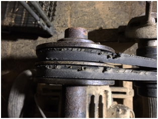
Poor alignment or incorrect installation are the most common causes of abnormal wear of sheaves and pulleys. On the other hand, increased productivity, fewer unplanned operational stoppages and reduced energy consumption are the result of well-aligned machines. In the long run, this is also positive for the environment. By aligning your belt-driven machines, you also reduce vibration that harms the machine and adversely affects the working environment.
One consequence of poorly aligned belt drives that is often overlooked is that incorrectly aligned or improperly tensioned belts can result in abnormal temperatures, caused by the belt’s friction against the pulley. Excessively high temperatures will cause the belts to harden, resulting in cracking. A toothed belt can lose teeth, leading to slipping and efficiency loss. Strong heat sources in the vicinity also affect belts negatively. A thermal camera can help to indicate potential abnormal temperatures.
WHERE DO I START?
Many belt manufacturers advocate preventive maintenance in order to avoid unforeseen stoppages. A scheduled operational stoppage is obviously more efficient and less costly than an emergency repair on a failed drive. However, having a maintenance program for your belt drives can also be efficient. There are a number of factors that determine how often you should perform preventive maintenance. Start by classifying your machines in these ways:
- How critical the machines are for your operation.
- The rotational speed of the machine.
- The drive’s impact on the environment.
- The current status of the drive (i.e., condition/quality of the belts and pulleys.)
When you have done this, you will be in a better position to know how to prioritize your maintenance work.
You should also think about the following:
- First and foremost, it is worth thinking about keeping the area around the machine free of dirt and debris, and ensuring that the base is in good condition.
- It is important for the person carrying out the maintenance to have the correct training and equipment to carry out the work satisfactorily. A laser pulley alignment tool is highly recommended.
- Check the machine manufacturer’s specifications regarding how to set up your machine correctly. Write this down so that it is easily accessible the next time maintenance is to be performed. This saves time.
- Check the belt manufacturer’s suggested belt tension values. A spring gauge to measure belt tension is an essential item in the aligner’s toolkit.
- Mixing different belt types or brands is not recommended.
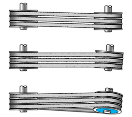
- If the transmission has several belts abreast, all the belts should be replaced together, even if only one is found to be defective.
- Measuring energy consumption before and after alignment is a simple way of verifying that you are now saving money.
- Listen to and look at the machine. If you suspect that anything is abnormal, you should investigate this. You should look out for unusual and abnormal wear or damage.
- Inspections should be performed frequently, perhaps as often as once a month.
- In addition, preventive maintenance should be performed at 6 to 12-month intervals.
- Follow the belt manufacturer’s instructions when replacing belts. Make sure that you also store belts correctly: don’t hang them, coil them flat! (Belts are a perishable product!)
Click here for examples of how much you can save by having your belt drives correctly aligned.
If you are ready to start improving the efficiency of your belts and sheaves, find the tool that best fits your needs.
by Yolanda Lopez
Reposted from EASY-LASER® blog
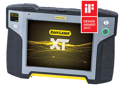
Easy-Laser® has been awarded the iF DESIGN AWARD 2017 for its design of a display unit for laser-based measurement equipment.
The display unit, XT11, won the Industry/Skilled Trades category and is part of a completely new concept within laser alignment, which was launched last year.
Rustan Karlsson, Head of Marketing at Easy-Laser®, states: “The award is an acknowledgment of the hard work that we have put into our next generation of products to make them even more user-friendly and attractive, in a way that is right for our users and our brand. Within our industry, it is like winning an Oscar!”
He continues: “The work really started three years ago, when our design office, Shift Design & Strategy, identified what Easy-Laser® stands for and developed a design guide. Together with our own engineers, they defined what has now been acknowledged by the iF DESIGN AWARD. It feels great to have won it, especially with the product launches ahead of us.”
The iF DESIGN AWARD is one of the world’s most prestigious competitions. The entries are assessed by a jury of 58 professional designers from around the world. This year’s competition was tough, with over 5500 entries from 59 countries.
Learn more and download the brochure of the award-winning Easy-Laser® XT11 display unit featured in the XT440 shaft alignment system.
by Ana Maria Delgado, CRL
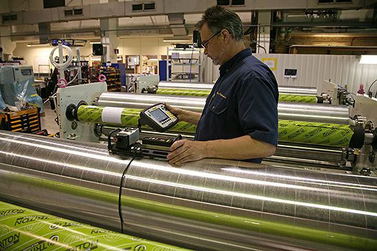
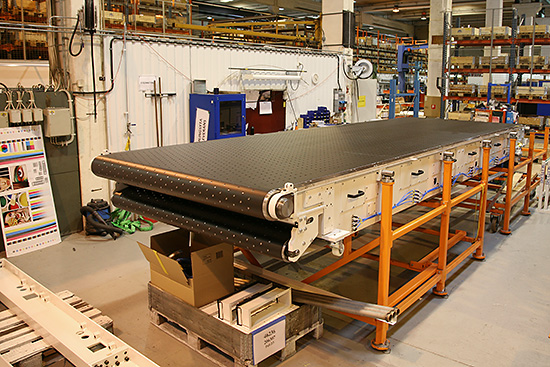
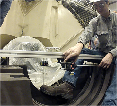
The Easy-Laser E970 laser roll alignment system is a well-established product proven to be effective in many parallel roll alignment applications such as in printing presses, steel, aluminum, and paper mills. We recently completed a roll alignment at a stainless steel roll slitting facility.
Setting the system up was fast and easy, from establishing a reference roll to creating new benchmarks. Rolls were measured for both level and skew.
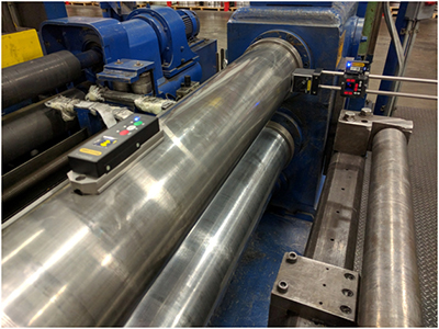
Corrections were done on-site with live monitoring. The system was able to accurately measure traditionally challenging rolls with unusual surfaces, including rewinder rolls and non-magnetic rolls, such as the guide roll with a rubber surface.

The asset owner requested that the slitters and guides be checked and asked whether that was possible. The versatility of this system allowed for such an operation. By profiling the laser to a reference roll, the slitters were checked for alignment and the required adjustments were made.
The job was scoped for two days, yet the entire job with slitter alignment was completed in less than one day. This provided the time to complete a roll alignment on an entirely separate finishing operation.
The proof of good parallel roll alignment lies in the results, after running the machine: the laser aligned rolls produce consistent material thicknesses to tolerance, thereby saving tens of thousands of dollars of potentially wasted money in scrap product, not to mention if a roll had to be scrapped for this process. The E970 is an accurate performer whose versatility is straightforward by all measures™
by Daus Studenberg CRL
Reposted from EASY-LASER® blog
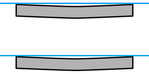
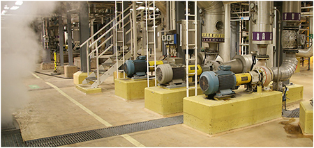
There are basically two types of pipe strain: static and dynamic pipe strain. Static pipe strain occurs both when the machines are operating and when they’re not running. This is most likely the type you’ve been trying to eliminate. Dynamic pipe strain, on the other hand, is a condition that only takes place when the machines are operating.
PIPE STRAIN AND ALIGNMENT
Strain, which is the deflection and positional change resulting from pipe stress, comes from the suction and discharge piping, and creates stresses on the machine frame or casing that in turn spread to the equipment body. A result of this is often a change in the alignment of the shaft. It also results in distortion of the machine casing which misaligns the bearings within the machine, resulting in very harmful vibration and increased radial loads on the bearings. So, before attempting shaft alignment, you should ensure that suction and discharge piping are not causing strain on your machines.
HOW CAN YOU CONTROL PIPE STRAIN?
Static pipe strain and its effects are fairly simple to control, and you can use any of the Easy-Laser® shaft alignment systems to measure the strain and help eliminate it. Here’s how: simply mount the system in the normal manner as when you perform the shaft alignment. Then:
- Position the measuring units at twelve o’clock. Use the Values program and set both units to zero.
- Rotate the shafts to the three o’clock position, and note if the values are not zero. Rotate the shafts back to twelve and confirm the zero setting.
- Now connect or disconnect the piping. Any changes to the values for the twelve and three o’clock positions is the result of pipe strain and should be corrected, which will require careful pipe fitting. What you are seeing is movement transmitted through the casing to the bearings and shaft.
Dynamic pipe strain is more difficult because it only occurs when the machines and piping are at operating conditions. And a good proportion of this type of pipe strain may be a consequence of the thermal expansion of the piping and the weight of the system fluid. This explains why the dynamic pipe strain is not a fixed state and why it might be difficult to handle.
We understand that this can be quite a challenge, however, we believe you have a lot to gain from minimizing dynamic pipe strain. And there are effective tools for this purpose: Our Easy-Laser measuring program has a great feature that registers measurement values automatically for a specified amount of time and frequency of measurement. This is very useful for looking at the differences between a machine that’s up and running and one that’s down. The data can also be transferred to the EasyLink™ software, where you can see the results more clearly, in the shape of a graph to scale.
IN CONCLUSION
The existence of pipe strain indicates that more than just alignment is needed for optimal machine performance; there are other important factors to take into consideration. This requires flexible measurement systems that will support you and help you reach your goal. You need more than a shaft alignment system; you need a total alignment solution.
We invite you to watch our Pipe Stress Know-How video to learn more about the effects of running equipment with pipe stress.
by Yolanda Lopez
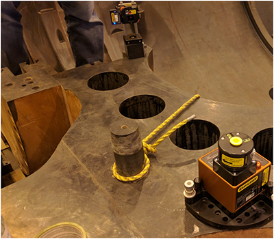
Steam turbine internal alignment applications require high precision, ease of use, and reliability. The Easy-Laser® E960 system is used to align diaphragms and internal components and delivers all these things.
 Setup is fast and simple. There is no need to precisely center your detector to the bore or the laser to the rotor to perform position checks. Simply orient the sensor into laser range, and the display unit does the rest to calculate the center. Your rotor positions are entered digitally for greater accuracy and speed of setup. Wireless components streamline the setup—no cables to get in the way!
Take three points over 180 degrees on a bore just as you would with a tight wire, or use the multipoint measurement to find the center of bores and check for ovality.
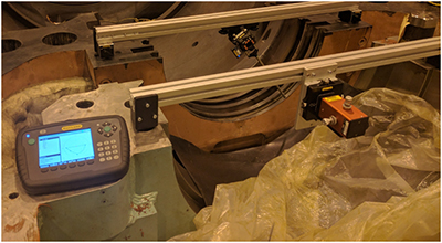
The Easy-Laser E960 features an optional reference control sensor for greater reliability and precision. No more guessing whether your reference line (the laser beam), moved during measurement—you are in control of its position at all times. Even if the beam moves over time due to environmental factors, the reference control sensor allows the system to automatically adjust for such movement to ensure all your readings stay highly accurate.
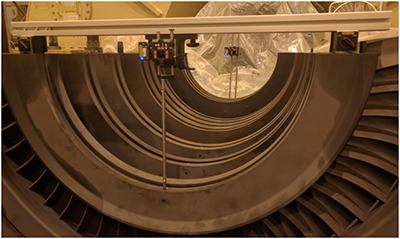
Need to measure the flatness of the shell? Simply add the D22 rotating laser and flatness readings can be taken using the same sensor as the one you use for internal bore alignment. Both the top and bottom shells can be measured without having to remove the bolts.
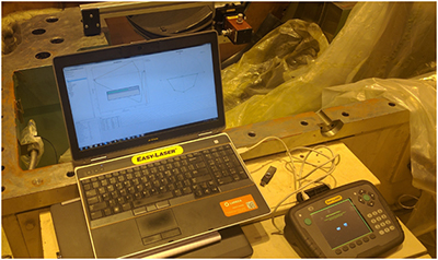
This system works with your existing processes. The Easy-Laser E960’s intuitive display allows for entry of diaphragm positions into your excel spreadsheets or takes advantage of the included Easy-Link software to present, process, and document the turbine alignment in one complete and easy to use package.
by Daus Studenberg CRL
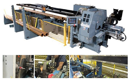
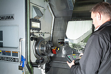
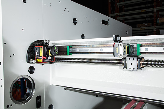
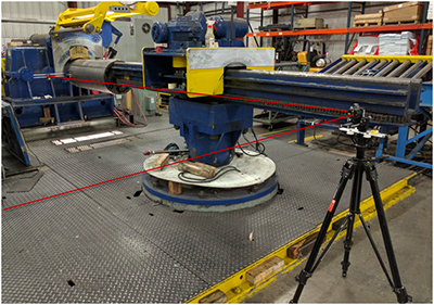
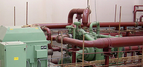
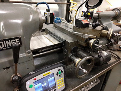
Recently, I&E Central (along with a service partner) used the Easy-Laser E940 Machine Tool system to perform alignment on an automatic lathe similar to the photo above. The lathe has an automatic feeder for 20’ sections of tube stock which are supported alternately by V-rollers and then clamped by “steady rests” while being machined. The objective of this job was to have the stock in perfect alignment with the rotational center of the spindle when supported by either V-rollers or the steady-rests. In addition, there is a pusher system that advances the stock into the collet. The movement of the pusher needed also to be aligned with the spindle centerline. This was a challenging measurement made possible by the availability of a spindle laser that could be directed back through the collet.
Measurement Procedure:
A laser transmitter was mounted in the spindle with its beam directed through the collet. The laser was adjusted to the rotational centerline, then the spindle was turned at 200 RPM for measurement. In this way, the beam precisely marked the rotational center along the entire length of the machine.
The first measurement was the location of the center of each steady rest. A laser detector was mounted on a short piece of stock, which was locked in each steady rest for measurement. A center of circle straightness program was used to measure and adjust the position of each steady rest. These were adjusted “live” so that each steady rest held the stock in line with the spindle rotation.
Once completed, pk-pk deviation in the vertical plane was 0.0095”, in the horizontal plane it was 0.020”, well within the customer’s desired specifications.
The next step was measuring the straightness of travel of the pusher arm relative to the rotational center of the lathe. This was accomplished by grasping a similar piece of stock with the jaws of the pusher, then using the same program to measure and adjust its true position at 4 locations along its travel.
The final adjustment involved adjusting the V-rolls to support the tube stock in line with the center of rotation. This adjustment was actually done without the laser. A full-length piece of stock was secured in the collet with the other end supported by the pusher. Each V-roll in turn was adjusted with shims so that it supported the stock precisely on the centerline. The customer tells us that the machine now runs smoother than it ever has.
The measurement and alignment of this machine section were never performed by the customer or any service contractor in that they had no way to make the measurements. The power and flexibility of the Easy-Laser E940 system made this a straightforward job that was completed in 1 day.
Special thanks to Bob Dunn with I&E Central, Inc. for sharing this case study with us!
by Ana Maria Delgado, CRL
The new Easy-Laser 12.0 firmware now features a handy table that lets you instantly see how well your readings repeat and save comments for them. When performing laser shaft alignment it is a best practice to take two sets of readings immediately after system setup to establish repeatability. Bad repeatability can signal measurement problems such as loose or faulty components, brackets rubbing, backlash between shafts, loose bearings and other causes. The repeatability table lets you establish confidence in your readings before you proceed to carry out adjustments on the machines.
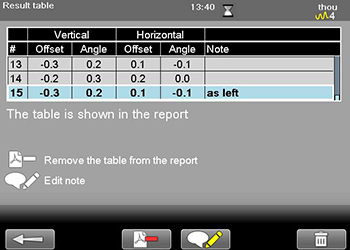
Hurry and upgrade your Easy-Laser E710 shaft alignment computer to this latest firmware. It’s free!
by Ana Maria Delgado, CRL
Reposted from EASY-LASER® blog
Engineering no doubt spends a lot of time deciding what machines should be specified and how best to set them up for optimal production. And you already know how important shaft alignment is. But there are other ways to make your machine perform even better and last longer. A careful base setup is key if you want to increase the machine’s lifespan and avoid unexpected downtime and other disturbances.
Why you should pay attention to the base setup?
Setting up the base properly is more important than many realize; it is crucial if you want to avoid unnecessary machine stress, and prevent costly problems in the long run.
First, the base has to be strong enough to support the weight of the machine. It also has to be able to withstand a large amount of torque and other loading that the machine produces. In addition, the base also needs to be flat and level.
An uneven or unleveled base can cause all kinds of issues for you: shaft misalignment, pipe strain, distorted machine frames (soft foot), etc. Even a small defect can have significant negative consequences on production.
The machine base – A great investment!
A base that’s flat and level will increase the machine’s lifespan and will save you unexpected downtime with costly repairs. You will also benefit from increased production time and greater efficiency of the machine with reduced energy consumption.
EASY-LASER E720 Alignment/GEO system
Don’t just eyeball the base to see if it’s flat. Use a laser. You might already be familiar with shaft alignment lasers. In this case, you need another kind of measuring tool, such as the Easy-Laser E720 system. The point laser will allow you to optimize both base flatness and shaft alignment. The Easy-Laser D22 (swiveling laser) will help you level the base. No other system on the market offers this type of flexibility.
by Ana Maria Delgado, CRL
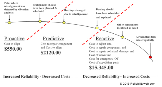
The Potential to Failure Curve (or P-F Curve) gives the user information on how an asset behaves before a failure occurs. This example is focused on failure due to misalignment. The goal of a reliability-focused plant is to be as far to the left on the curve as possible. While some companies are doing predictive maintenance work in an effort to reach the left side, many companies today are on the right domain of the curve, doing reactive work. Being in the reactive domain—putting out fires as they say— increases maintenance costs. This forces a company to perform unplanned work causes unscheduled downtime, and higher costs to expedite parts. Using technologies like ultrasound, thermography, and vibration analysis will catch an asset in a pre-failing state. This allows time to plan and schedule the repair to take place. However, with the right processes in place, the technician should recognize the misalignment of the machine before it causes components to fail. The ultimate goal is to be so far left on the curve, that it is off the chart, at the point where all the efforts (flat and rigid bases, accounting for thermal growth, eliminating soft foot, precision alignment, etc) are made so that the machine never runs misaligned.
by Adam Stredel CRL
Reposted from EASY-LASER®
There are many consequences resulting from having a poorly functioning measurement and alignment system. If there is any uncertainty concerning your laser system’s functionality, the measurement and alignment process could take longer than necessary. If the system isn’t in perfect working condition you might need to double-check your results more than once. The wrong alignment of the production equipment caused by incorrect measurements can lead to problems with the machines, as well as compromised product quality. Check calibration of your laser system at the recommended intervals or sooner to guarantee good alignment, peace of mind, and ensure that you always have the latest firmware version installed.
by Ana Maria Delgado, CRL
It can be argued that lubricants are the lifeblood of equipment. It is extremely difficult to assure equipment reliability when lubrication integrity is not maintained. The key is to keep the lubrication system clean, cool, and dry.
According to the Arrhenius Rate Rule, every 18-degree (F) increase in oil temperature in operation reduces oil life by half. Excessive lubrication temperatures can lead to additive depletion, oxidation, varnishing, hazards, corrosion, increased frequency of oil changes, and more. All of this leads to reduced equipment reliability and increased costs.
Reduced operating temperature is one of the many benefits associated with proper machinery alignment. This in turn will help you reduce the operating temperature of the lubricants (lifeblood) within your equipment. Best practice equipment reliability includes proper equipment alignment. Your best practice lubrication efforts should include making sure your equipment is operated within proper alignment tolerances. Doing so will help you maintain the “cool” required to ensure that the lifeblood of your equipment is protected.
by Trent Phillips CRL CMRP - Novelis
Problem: The machine shop of the engineering department of a prestigious Florida university wanted to identify the source of error in their tool room lathe. They had previously observed that when working pieces further away from the spindle chuck, there was an appreciable deviation in accuracy compared with close-to-the-spindle work.
The machine shop instructor suspected the problem to lie somewhere in the tailstock and asked us to confirm or refute his suspicions.
Solution: The Easy-Laser E940 Machine Tool laser alignment system was used to perform three types of measurements:
- Z-axis straightness measurement
- A spindle direction measurement
- A spindle-to-tailstock alignment measurement
In addition, the Values program was used to check for play in the tailstock sub-spindle bearings. An additional check was performed to verify whether the tool support returned to its original position when it was unlocked, and then locked again.
After accomplishing the above measurements and checks, it was determined that the straightness of the Z-axis was within tolerance, the spindle direction was ascertained and the alignment between the spindle and tailstock at the furthest distance revealed a small angle. There was no significant play in the sub-spindle bearings and the tool support check was good.
This data allowed the instructor to narrow down the possible corrective actions to take in order to achieve a better alignment and return the lathe to an optimum performance condition.
The ability to perform all of these checks and measurements to a high degree of accuracy allowed the university to quickly and more certainly identify worn components, which will save them a great deal of money in spares costs, as well as ensure that parts and workpieces fabricated on this lathe will turn out as expected, on time and within design tolerances.
by Oliver Gibbs CRL
May 2016 · Plant Services Magazine
Like a lot of reliability engineers, Joe Anderson, former reliability manager at the J.M. Smucker Co., appreciated – in theory – that precise pulley alignment is critical to preventing vibration problems and ensuring successful operations.
My understanding was, ‘Yeah, we need to do it,’ ” Anderson says. “But you always have these excuses.”
When the Smucker’s plant at which Anderson worked launched a dedicated vibration monitoring and control program a year-and-a-half ago, though, Anderson quickly became a convert to making precision alignment a priority.
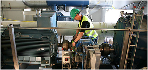
The plant purchased a vibration analyzer (VIBXPERT®) and laser alignment tool (the SheaveMaster® Greenline) from Ludeca to help aid in identifying machine defects that appeared to be linked to vibration caused by misalignment. Laser alignment allowed for correcting vertical angularity, horizontal angularity, and axial offset – the three types of misalignment – simultaneously. Whoever was using the laser alignment tool, then, could be sure that adjustments made to correct one alignment problem didn’t create an issue on another plane.
Read the entire article to learn how J.M. Smucker Co. made precision alignment a priority: Get your alignment in line: Don’t jiggle while you work
by Ana Maria Delgado, CRL