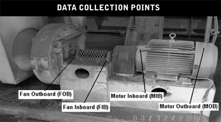
 To facilitate the initial learning curve, a labeling system was implemented to help technicians collecting data identify bearings that were part of the initial survey. These descriptors were laminated to prolong their life in the unfriendly environment of a typical cement plant. Standard locations for data collection needed to be understood since labels would become difficult or impossible to read over time.
On-the-job training included an understanding that readings collected on the drive motor bearings needed to be collected from the grease fitting on the non-drive end and from the upper portion of the end bell housing on the drive end. On driven equipment bearings, where direct access was possible, the ultrasound readings were to be taken in the horizontal plane directly from the bearing housing. (Note: with ultrasound, it is not necessary to record data from multiple planes on the same bearing). Technicians were trained to take ultrasound readings as close to the bearing as physically possible while respecting personal safety.
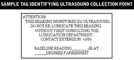
This simple label proved important to the integrity of the pilot project to prevent greasing from well-intentioned lubricators.
by Allan Rienstra - SDT Ultrasound Solutions
Hopefully, your company has global, regional and facility resources dedicated full time to reliability initiatives.
These resources are necessary to help ensure improvements in maintenance, equipment run-time, capacity, profits, and much more.
The question you and your organization should be asking is “who is the reliability leader in your organization”?
The answer may seem simple but could be quite surprising when given serious consideration. The answer should be “everyone”. The truth is that most implementation efforts in a facility or company fail. Unfortunately, this is very true for maintenance and reliability improvements. The reason is that not “everyone” is committed to the effort. Sustainable reliability requires understanding and dedication from many different groups within an organization. Supply Side, MRO Stores, Engineering, Procurement, Maintenance, Management, Operations, and Training must all understand the strategic value in reliability efforts and cooperate with each other. Otherwise, failure and unsustainability may be guaranteed.
If the answer to the question is that the “Reliability Engineer” and/or “Global Reliability Leader” are the individuals responsible, then your journey may not be complete. Your organization should have training in place to demonstrate the value and create understanding in all of these groups about reliability. Procedures should be in place to ensure that proper reliability best practices are considered in the design, procurement, installation, operation, and maintenance. Failure to do so will result in increased life cycle costs of the equipment, reduced capacity, and reduced profits.
Remember that your maintenance department cannot overcome poor equipment design, installation, or operation.
by Trent Phillips CRL CMRP - Novelis
Compressed air represents one of the highest utility costs in industrial plants. It’s also one of the most misunderstood; which explains why leaks account for, on average, as much as 35-40% of total demand.
Leaks are often considered an unavoidable cost of business. Many of us simply don’t realize the high cost of compressed air leaks.
Add to that the fact that:
- Leaks don’t present a visible threat to safety
- Leaks don’t make a mess on the floor
- They are invisible
- We can’t hear them over the other noise in the plant
- We don’t need permission to open a 1/4” air line and waste thousands of dollars per year
Remove our misconceptions about the high costs of leaks and we create a huge opportunity to save money, increase environmental sustainability, and drove positive culture change.
Download the Leak Surveyors Handbook to learn more.
by Allan Rienstra - SDT Ultrasound Solutions
Reposted from EASY-LASER® blog
Engineering no doubt spends a lot of time deciding what machines should be specified and how best to set them up for optimal production. And you already know how important shaft alignment is. But there are other ways to make your machine perform even better and last longer. A careful base setup is key if you want to increase the machine’s lifespan and avoid unexpected downtime and other disturbances.
Why you should pay attention to the base setup?
Setting up the base properly is more important than many realize; it is crucial if you want to avoid unnecessary machine stress, and prevent costly problems in the long run.
First, the base has to be strong enough to support the weight of the machine. It also has to be able to withstand a large amount of torque and other loading that the machine produces. In addition, the base also needs to be flat and level.
An uneven or unleveled base can cause all kinds of issues for you: shaft misalignment, pipe strain, distorted machine frames (soft foot), etc. Even a small defect can have significant negative consequences on production.
The machine base – A great investment!
A base that’s flat and level will increase the machine’s lifespan and will save you unexpected downtime with costly repairs. You will also benefit from increased production time and greater efficiency of the machine with reduced energy consumption.
EASY-LASER E720 Alignment/GEO system
Don’t just eyeball the base to see if it’s flat. Use a laser. You might already be familiar with shaft alignment lasers. In this case, you need another kind of measuring tool, such as the Easy-Laser E720 system. The point laser will allow you to optimize both base flatness and shaft alignment. The Easy-Laser D22 (swiveling laser) will help you level the base. No other system on the market offers this type of flexibility.
by Ana Maria Delgado, CRL
As Published by Maintenance Technology Magazine August 2016 issue
Clinging to a single approach that made economic sense for your plant ‘back in the day’ could be an expensive strategy.”
Overall values are the most common measurements and calculations used in vibration analysis. What’s more, some reliability and maintenance programs rely solely on them. The goal is to remove monitored equipment from service once the overall vibration level exceeds a certain threshold. Although this approach would appear to be quite cost-effective, in reality, it frequently isn’t. In fact, overall vibration monitoring can become extremely costly for a facility.
If you are asking yourself questions such as: What should you do once an overall vibration level exceeds your target amplitude and the equipment is removed from service? Who should collect routine vibration data? What other valuable condition-monitoring data might be missing? Or how do you motivate others to take corrective actions? then this article is definitely a must-read.
by Trent Phillips CRL CMRP - Novelis
Reposted from EASY-LASER®
There are many consequences resulting from having a poorly functioning measurement and alignment system. If there is any uncertainty concerning your laser system’s functionality, the measurement and alignment process could take longer than necessary. If the system isn’t in perfect working condition you might need to double-check your results more than once. The wrong alignment of the production equipment caused by incorrect measurements can lead to problems with the machines, as well as compromised product quality. Check calibration of your laser system at the recommended intervals or sooner to guarantee good alignment, peace of mind, and ensure that you always have the latest firmware version installed.
by Ana Maria Delgado, CRL
It can be argued that lubricants are the lifeblood of equipment. It is extremely difficult to assure equipment reliability when lubrication integrity is not maintained. The key is to keep the lubrication system clean, cool, and dry.
According to the Arrhenius Rate Rule, every 18-degree (F) increase in oil temperature in operation reduces oil life by half. Excessive lubrication temperatures can lead to additive depletion, oxidation, varnishing, hazards, corrosion, increased frequency of oil changes, and more. All of this leads to reduced equipment reliability and increased costs.
Reduced operating temperature is one of the many benefits associated with proper machinery alignment. This in turn will help you reduce the operating temperature of the lubricants (lifeblood) within your equipment. Best practice equipment reliability includes proper equipment alignment. Your best practice lubrication efforts should include making sure your equipment is operated within proper alignment tolerances. Doing so will help you maintain the “cool” required to ensure that the lifeblood of your equipment is protected.
by Trent Phillips CRL CMRP - Novelis
Today’s more evolved ultrasound data collectors present results that take reliability practitioners beyond the single decibel. Using only an overall dB value may indicate something inside the machine has changed since the last readings were taken. But it provides no additional insight to determine what type of defect may be present.
Moreover, a single dB only provides a useful trend if the inspector has control of the acquisition time during data collection. Acquisition time needs to be adjusted in concert with the speed of the machine. More time for low-speed applications and less for high. The aim should be to capture a minimum of 2-3 full shaft rotations.
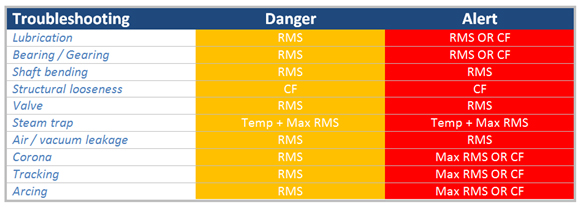
The SDT270 takes inspectors beyond the single decibel by presenting ultrasound data in terms of machine condition. We call them Condition Indicators and there are four (RMS, Max RMS, Peak, and Crest Factor (CF)) and are abbreviated as 4CI. Ultrasound identifies defects in machines when those defects produce one or more of the following phenomena: FRICTION, IMPACTING, or TURBULENCE (FIT).
Some examples:
- A bearing that requires lubrication will present higher levels of friction. Therefore, an RMS danger alarm will be triggered at 8 dB and an RMS/CF alarm when severity increases.
- A bent shaft produces higher levels of friction and therefore presents danger and alert warnings with the RMS condition indicator.
- Electrical defects such as arcing, tracking, and corona are first alarmed with the RMS condition indicator and severely alarmed with Max RMS and CF.
- A faulty steam trap is detected with an elevation in Temperature and Max RMS.
Traditional ultrasound is useful for trending decibel levels that alert us when machine condition changes. Evolved ultrasound goes beyond the single decibel to recruit Condition Indicators that help inspectors determine the type of defect that is creating the alarm. SDT’s Four Condition Indicators demonstrate how ultrasound must be used for both defect alarm and identification.
by Allan Rienstra - SDT Ultrasound Solutions
The maintenance and reliability world is filled with key performance indicators (KPIs). Properly tracking KPIs can be challenging due to difficulties in obtaining accurate data and the time required to obtain them. The key is to pick KPIs that will help you identify and drive the behavior that you need to change right now. As advances are made, additional KPIs can be added which help identify and drive additional behavior changes and improvements.
It is very important to understand that KPIs can lead to false-positive indications and never actually result in value-added or sustainable improvements within your organization. You must understand and address the true root causes behind a deficient KPI and eliminate them.
For example, mean time to repair (MTTR) can be a very good indicator leading to great improvements.
Unfortunately, this indicator can also be harmful if misunderstood or given the wrong improvement focus. What if individuals decide to take deleterious shortcuts to quickly get a machine operational again? MTTR may seem to improve on that machine, but did overall asset health and reliability really improve, in a meaningful way that provides real value back to your organization? These shortcuts may actually lead to additional machinery failures and greater downtime.
MTTR could be an indication that maintenance staff requires training on how to properly repair the machine. Too short and perhaps unwanted shortcuts are being taken. Too long may indicate that excessive time is being wasted hunting for tools or spare parts due to a lack of proper planning and/or kitting. Is a detailed and efficient work plan available, to guide your maintenance staff incorrectly repairing the equipment? MTTR, if properly used and tracked can point you toward areas of substantial improvement.
Never forget to determine and address the root causes of equipment failure. Doing so may eliminate the need to work on the equipment in the first place. Prevention is always the best way to drive sustainable improvements in uptime and capacity.
Beware of driving improvements in KPIs for the wrong reasons. This can lead to a false sense of progress that never brings about real changes and advancements in reliability to your organization. Ensure that you understand the real variables driving the KPIs you have selected. Don’t let your chosen KPIs give you a false sense of improvement!
by Trent Phillips CRL CMRP - Novelis
How do you obtain the desired return on your assets? Availability, maintainability, and reliability are foundational elements required for a proper return on your equipment. Condition Monitoring is a tool that can help you build these elements and obtain the desired returns. Condition Monitoring can be completed while equipment is running to maximize uptime and help provide better overall reliability. Conditional changes can be identified before functional failures that result in downtime occur, preventing other unwanted consequences.
Unneeded work can be avoided (unnecessary PMs, failures, etc.), and better planning and improved scheduling achieved through CM.
Use Condition Monitoring as a means to build a solid foundation for your facility!
by Trent Phillips CRL CMRP - Novelis
Companies spend lots of money, time, and effort on systems to document what needs to be done, what should have been done, failures that occurred, etc. Unfortunately, these systems usually show and document the point of failure (F) and not the point of conception (P) for a problem. These are examples of downtime systems and are important for success.
Does your company invest in uptime systems and processes? What is an uptime system or process? These systems help your facility identify the point of conception (P) of a problem. This is very important because it means your facility has more time to mitigate a problem before it results in unwanted consequences (injury, downtime, increased costs, poor quality, less main profit, etc.)
Condition monitoring (CM), reliability efforts, proper planning, and scheduling, kitting, effective PMs, reliability-based engineering, etc., will reduce the amount of information that must be entered and tracked through the downtime systems that have been heavily invested in. The results can be extremely rewarding.
What uptime systems and processes does your facility utilize?
by Trent Phillips CRL CMRP - Novelis
March 2016 · Empowering Pumps Magazine
“Work smarter, not harder” is a statement we have all heard before, but who has the time to think about smarter ways to work when there is so much work to be done? Some maintenance professionals are so busy trying to keep their operation running smoothly that they often address equipment issues “reactively”. This might make maintenance teams feel more like “firemen” as they respond to in-the-moment needs. So how does a company become less “reactive” and more “proactive”?
Read the full article: Maximize Uptime with Asset Condition Management to better understand the key components of an Asset Condition Management (ACM) Program and how core technologies like Alignment, Balancing Vibration Analysis, and Ultrasound Testing can help you increase uptime.
by Dave Leach CRL CMRT CMRP
Guest post by Karl Hoffower – Condition Monitoring and Reliability Expert for Failure Prevention Associates
Location and placement of your sensors are crucially important when doing predictive vibration analysis.
1) Below is an example of proper sensor installation on a cooling tower gearbox. These two sensors are placed in different directions to follow both the gearbox vibration as well as indicate if the fan blades become unbalanced.
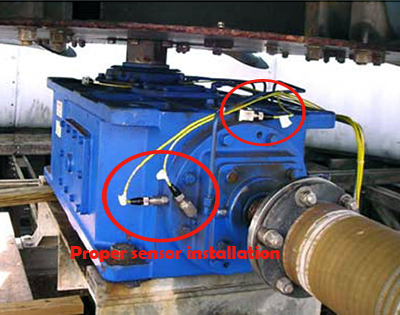
Read Vibration Sensors for Cooling Towers case study from CTC for details on proper sensor installation on cooling towers.
2) This example of poor sensor placement is on a vertical motor using a belt drive for a fin fan.
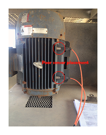
PROBLEM
- The vibration sensors pictured on the left are attached to one of the motor fins. Watching these sensors, one could visually see the fin and sensors oscillating as if on a trampoline.
SOLUTION
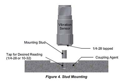
- The choices are to face, drill & tap (see figure #4 below).
- The other option would be to epoxy a mounting pad to the bearing housings. Then screw the sensor into the mounting pad.
3) Another example of poor sensor placement on a 4-20mA shutdown switch on a gas recipient compressor at a facility in Texas.
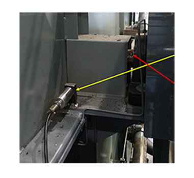
PROBLEM
- The vibration sensor (yellow arrow) is a 4-20mA accelerometer used for asset protection in an automatic shutdown setting. It is monitoring the overall vibration levels emanating from the bearings and shaft (red arrow).
SOLUTION
- The better choice would be to use a mounting pad attached to the pillow block bearing.
by Yolanda Lopez
Reposted from RELIABILITYWEB®
- Assemble a team and identify applications for a program
- Justify needs by recognizing key areas where improvement can be benchmarked
- Set written goals for the program
- Establish how ROI will be measured
- Purchase quality ultrasonic inspection equipment
- Invest in certification training at both management and user levels
- Choose a leader to technically carry the program forward
- Establish a system to reward the successes
- Frequently review the progress as part of regular meetings
- Ensure everyone involved is 100% mentally invested in the program’s success
Tip from Hear More: A Guide to Using Ultrasound for Leak Detection and Condition Monitoring by Thomas J. Murphy and Allan R. Rienstra.
To learn more about airborne ultrasound, download a chapter preview of Hear More.
by Allan Rienstra - SDT Ultrasound Solutions
Does your maintenance staff have to wait on parts, wait for the equipment to be available, search for tools to do their job, work lots of overtime, travel long distances to the job, etc? Most maintenance staff work in pairs. This means that when you see one of your maintenance staff struggling to do his job, then his counterpart is struggling as well. What is the result? You may have a hidden cost (twice the labor) that you did not realize!
What can you do to avoid this? Make sure that your work is correctly planned. Job plans should be created, and be accurate and available. The required parts should be staged once the work is planned. Machine drawings, special tools, permits, etc., required to complete the maintenance activity should be identified in the job plan and be available as part of the job kit. Once all of this is done the work should be scheduled. These steps will help your maintenance staff focus on work and not on searching for the resources they need to complete their assigned maintenance tasks. You will save money and have more reliable equipment.
by Trent Phillips CRL CMRP - Novelis
Did you know that equipment PMs (Preventive Maintenance) tend to become more expensive over time? Why does this happen? For example, additional maintenance steps tend to be added to a PM as time passes. The machine configuration (design installation) changes and the PMs are never updated to reflect these modifications. Some PMs are not written correctly in the first place. All of this means that unnecessary maintenance is performed on your machines costing a lot of resources and money for a very long time. These are just some of the reasons PMs can be costly.
RCM and FMEA functions usually cost more money upfront and tend to be avoided as a result. However, these functions can clearly identify what maintenance actions should be performed on equipment and guide you to steps that will avoid maintenance issues. Condition Monitoring is another tool that works directly with RCM and FMEA functions to reduce PM activities and drive better equipment performance and reliability. These activities may cost more upfront versus a PM but will be much more cost-effective in the long run.
by Trent Phillips CRL CMRP - Novelis
Can a Reliability Engineer or Reliability Manager make a facility or organization reliable? This is a very important question that may be worth discussing within your organization to ensure proper expectations and success.
A more practical definition of reliability may be:
Equipment performs the way you want it to when you want it to”.
Reliability is very easy to define, stuff but achievement of this simple goal is complex and unfortunately unattainable for many organizations. Reliability requires a holistic approach that involves the complex interaction of Maintenance, see Operations, Supply Chain, Engineering, Procurement, Management, Process, and Vendors. Consistency, focus, and strategic implementation directly correlate to the success of any effort and this is true for your reliability efforts. Therefore, a consistent and strategic top-down focus is required from management and throughout each of these groups. Organizational misalignment leads to competing groups and will make sustainable reliability within your organization extremely difficult, and maybe even impossible to achieve.
Reliability Engineers and Managers can support reliability through leadership, training, tools, etc. However, the answer to the question is that everyone within your organization is responsible for reliability. It is critical that everyone within an organization understands this and that reliability is made a goal for each of these groups with defined metrics to track understanding and achievement.
So, who owns equipment reliability in your plant? The answer is Everyone!
by Trent Phillips CRL CMRP - Novelis
Often, welding operations such as MIG and TIG will be occurring in the presence of your laser shaft alignment system. The question often comes up: will this light energy damage the optics? The answer is no.
However, if you must weld in the presence of your laser alignment system, a greater source of damage could be from the heat, sparks, and electrical energy that is emitted from the process. We do not recommend leaving equipment attached to anything being welded due to these dangers. Welding is like having a continuous lightning strike occur and electrical voltage differences and resulting magnetic fields could cause electrical damage. Remove your equipment to protect it from such hazards.
As far as light energy goes, OSHA has standards for minimum eye-protective shade numbers ranging from “4” for gas welding to “11” for shield metal arc welding and finally up to “14” for carbon arc welding processes. NASA recommends a number “14” for directly viewing solar eclipses. All of this is for protecting the human eye, which is less resistant to damage from light than a laser detector. A laser detector is designed to continuously absorb direct laser light energy over a continuous period of time. This is far more light energy than the human eye would encounter from arcs and sunlight with proper protective gear. Warning labels caution you not to stare directly into the laser beam!
Many laser alignment systems have a special protective coating on the detector that is optimized for the specific laser wavelength of light it is intended to detect. This helps prevent interference from the bright sun from causing measurement errors. Many laser systems are used in bright sunlight, and some work better than others under such conditions. Since the welding energy would at most be of the same intensity as direct sunlight, this would most likely not cause damage. Of course, you could also put the protective caps on to be completely safe.
by Daus Studenberg CRL
Most companies focus on repairing equipment after some functional failure has occurred and getting the equipment operational again. Is that the primary focus of your facility? Different studies have been completed by different organizations, which, while the percentages are different, all point to some very consistent and vital information. Design (engineering), installation (contractors, internal resources) and operation of the equipment all introduce equipment defects and drive reliability in your facility. Maintenance cannot overcome poor design, installation, and operation. Your maintenance staff can only deal with (repair) the consequences.
Your reliability efforts should be focused on preventing the introduction of defects in your equipment. This will help ensure equipment reliability leading to lower maintenance costs, increased capacity, and other positive results. Ensure that your equipment is designed, installed, and operated with reliability in mind. Make sure that you focus on the prevention and elimination of equipment defects as well.
by Trent Phillips CRL CMRP - Novelis
The Mars Climate Orbiter was launched by NASA on Dec 11, 1998, to study the Martian climate. On its arrival at Mars on September 23, 1999, communication was lost shortly after an orbital insertion maneuver was performed.
The cause of the failure was a lower than anticipated altitude with a resulting burn-up of the orbiter. It was entirely due to human error. The error occurred because one piece of software entered the required force in pounds and a separate piece of software interpreted this as newtons. The result was a $125 million dollar lesson on the importance of consistency in units.
When performing an alignment, consistency with measurement units is the key to preventing costly errors. We recently conducted a training class for a company that worked on the metric system. Our alignment systems allow for easy conversion “on the fly” between imperial and metric units, so we simply operated everything in the metric system. We then started noticing that some students were taking much longer times on their alignments than usual. It became apparent they were misinterpreting the values of the shims, which are expressed in “thou” and thought they represented some form of a metric value. Fortunately, it was not a $125 million mistake as this can simply be a lesson to be learned in training.
When working with different units, consider all of the stakeholders involved in the project. Who will operate the tool? Who will make corrections? Who will interpret whether or not the alignment is acceptable? You will have to determine which units of measurement will be the standard for the entire project. Fortunately, if someone makes a mistake with units for corrections, they will most likely not see the alignment improving. However, if there is a mistake on units for acceptability criteria, this could be dangerous. There is a big difference between 1 mm and 1 thou! Avoid multiple conversions for the alignment process. Standardize on one set of units and remain consistent for the whole project. If there is a need to convert units during the alignment, make very sure everyone understands when this happens and why this is the case.
by Daus Studenberg CRL