
Proper vibration data collection and diagnostics require knowing the accurate operating (turning speed) of monitored equipment. The most common tools used for measuring equipment turning speed are a tach (tachometer) and strobe (strobe light). If a means to determine equipment speed is unavailable, then an advanced vibration analyzer like VibXpert® may have additional capabilities to help you make a precise determination.
Set your vibration analyzer to acquire a velocity spectrum via the Multimode capabilities. A lower fmax is ideal because that is where the turning speed will be identified. Also, be certain that the lines of resolution (LOR) selected are high enough to accurately measure all of the frequencies around the turning speed. For example, improper LOR selection may result in the driver (motor) and driven (fan, etc.) frequencies being combined/merged together in one peak. This can make operating speed determination inaccurate or impossible. Please note that with higher LOR settings the data will take longer to collect because additional data is being acquired by the vibration analyzer. The number of averages should be set to a minimum of four to make certain any non-periodic energy is filtered out during data collection. Once data collection is complete, a cursor can be placed on the first high peak which usually indicates the turning speed of the asset.
Also, Multimode data collection can be set to a continuous mode allowing the data to be viewed live as it is collected. Once stabilized, the cursor can be placed on the spectrum to determine the turning speed of that asset as described above.
by Mickey Harp CRL
You’ve got it, so why not use it? What am I talking about? Besides your vibration analyzer, you probably have other tools that can be utilized to deliver additional reliability information to your management and facility.
1. Visual inspections can be logged into your vibration routes to help your facility keep on top of a number of things, like:
a. Transformer cleanliness
You can log the transformer as:
- Clean
- Slightly Contaminated
- Dirty–Needs Attention
- Very contaminated – (reduced cooling capacity!)
b. Motor cooling fin cleanliness (same as [a])
c. Plant area cleanliness
- Clean
- Slightly Contaminated
- Dirty–needs attention
- Very contaminated – possible safety hazard
d. Plant area fire equipment condition
- Fire Equipment Ready!
- Hose missing!
1. Valve wrench missing!
2. Nozzle missing! - Extinguisher missing!
e. Record pressure, amperage, megawatts, etc. from gauges.
The list of uses for visual inspections goes on and on. Each inspection can be trended and reported. Many facilities struggle to keep up with some very important equipment or conditions around the plant, because it may not be easily worked into daily routines. If you are already in a routine of collecting vibration data, then you should take advantage of visual inspections. Add all the value you can to your tours through the plant! Find out what the Maintenance Manager or Production Manager might be very interested in knowing on a regular basis and add it to an existing route!
2. Do you have a strobe light? You can use it along with the “Visual Inspection” process spoken of above, and do visual inspections on critical machine couplings even while the machine is in operation. Take great care to remain safe, while getting valuable visual inspection data.
3. Do you have an infrared thermometer gun? If so, you can connect it to your data collector to record critical temperatures during a route and trend them. These are just a few suggestions of additional value you may be able to add to your maintenance and reliability efforts from other tools already in your kit and through visual inspections and data-logging activities.
by Mike Fitch CRL
Maintenance departments are often expected to collect data on critical equipment in a consistent manner in order to monitor the efficiency and maximize the life of such equipment. Doing this manually can pose safety or health hazards to those responsible for collecting the data. The solution is to install permanently mounted sensors with wiring directed to a termination/switch box.
There are several ways to permanently mount the sensor to the machinery, but the most common are:
- Adhesive: This consists of using a strong epoxy-like adhesive that will allow for a sturdy mounting. It is very critical that the two surfaces be thoroughly cleaned with a steel wire brush to remove any paint and/or corrosion that can compromise the integrity of the bond between the sensor and the machine.
- Drilling and tapping: This consists of drilling a hole into the casing of the machine and then tapping the hole to the thread of the stud included with the sensor. This last method is the preferred method as it will guarantee a completely solid bond between the sensor and the machine
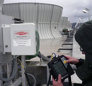
For whichever of the above methods is chosen, cabling will have to be routed. It is important to route the cable through the conduit so that it is protected from harsh temperatures or exposure that can potentially cause damage. When possible, utilizing a cable trough will help keep the cabling organized and away from any of the rotating components of the machine. Labeling the cables will guarantee that the final wiring in the termination/switch box becomes a smooth process. Once the routing of the cable is completed, thanks to the labeling of the cables, the wiring to the termination/switch box becomes very simple. Once the permanently mounted sensors are installed, the analyst in charge of the Condition Monitoring program can safely collect data with the help of a capable data collector such as the VibXpert® II. This will help the plant maintain a world-class reliability and maintenance program while ensuring the safety of its employees.
by Mario Rostran CRL
It is surprising that most users of Condition Monitoring (CM) technologies do not keep their software and/or device firmware updated. Many reasons such as having to pay for updates and support may explain why this happens.
Some of the disadvantages of not keeping your software and firmware updated are:
- You will not receive critical bug fixes. This means living with an annoying problem that may be resolved by simply updating.
- You will not receive feature enhancements. Maybe some of the new features you have requested or new functionality that will allow improvements in job performance is easily available by updating.
- Most vendors do not keep older versions of their software and firmware operational for support. This makes customer support much more difficult for all involved.
Some companies, like LUDECA, do not charge for support or update agreements on the products they provide.
Therefore, it makes even more sense to keep your CM hardware and software updated. Make sure that you keep your contact information updated with your vendor as well. They will wish to notify you when updates are available and can’t if no primary contact information or outdated information is provided.
Latest firmware and software for your LUDECA products.
by Trent Phillips
Some of the best engineers start out as technicians, operators, and mechanics. The reasons should be obvious but are not always understood. These individuals know how to install, operate and maintain equipment. A good manager, engineer, or Condition Monitoring (CM) Analyst should always seek the advice of equipment operators and maintenance employees. The value obtained from a simple conversation can be enormous. They can help with critical things that may otherwise have gone overlooked. This can help improve the design, installation, operation, or maintenance of equipment. The information they are capable of providing but isn’t being exploited may explain why routine reliability problems continue to occur. Never overlook the wealth of information that may be sitting next to you at lunch or working next to you each day!
Watch our Reliability Matters videos
by Trent Phillips
Guest post by Kasey McClain, Mechanical Engineer at Pioneer Engineering
Everyone knows that lubrication is crucial to the life of a bearing. Two common types of bearing lubrication are grease and oil. I commonly see oil bath lubrication and oil mist along with grease lubrication. One of the biggest problems that I have encountered with greased bearings is over greasing. When installing a new bearing assembly, it is important to note whether the bearings are pre-greased by the manufacturer. Over greasing will not allow the heat to dissipate from the bearing which will cause the bearing to expand and cause a tolerance stack-up which may then show bearing defects. This may also cause an existing defect to progress, decreasing the life of the bearing. With an oil bath lubrication system, too much oil can be just as detrimental as too little oil.
With too little oil, the slinger ring, or whichever component carries the oil, will not be submerged in the oil and will not be able to lubricate the necessary components. With too much oil, some of the components may not get the lubrication necessary. Oil mist systems have been shown to eliminate the issue of too much or too little oil.
However, running the mist system low on oil will cause the components to not be lubricated. Also, the oil misters can become clogged which would lead to a lack of necessary lubrication. This is why regular lubrication monitoring is necessary to keep equipment running smoothly for as long as possible. Attention to detail is essential in all aspects of machinery maintenance.
by Ana Maria Delgado, CRL
Alarms can save time and assist in the notification of impending issues when analyzing vibration data within your Condition Monitoring software. Of course, the correct alarms must be set in order for the analyst to perform his or her job correctly. Too many times the incorrect levels are set for alarms causing a machine to either be constantly in alarm or for the monitored conditions never to reach the required levels to alert the analyst of an issue that should be alerted.
OMNITREND® software has many different alarms that can be configured to assist the analyst in performing their job. Over time the running condition of a machine will change and it is important to make certain that the alarms are also checked and tweaked if needed. An alarm value might need to be changed many times over the life of a machine.
OMNITREND has a feature that allows the end-user to view the collected data and adjust or set alarms according to the machines’ vibration levels. These “smart alarms” should be set after collecting data for at least three months. The three-month period allows the analyst to view how that machine has operated over that time period.
The ability to display many different data readings at once on the same screen is provided. This allows for smart alarms to be configured using the vibration levels from the machine. Do remember that a machine’s vibration signature will change over time. Be certain to update your alarms with that information in mind.
If you have any questions or need assistance configuring alarms within OMNITREND please contact us. Our hardware and software support is offered at no charge to our valued customers.
by Mickey Harp CRL
What are some of the most common techniques that should be used every day in a vibration analysis program?
-
Spectrum Analysis
Spectrum Analysis is used to help identify the normal operating frequencies of a machine. Additionally, the defect frequencies and their characteristics can be routinely identified.
-
Waveform Analysis
Waveforms are one of the most overlook analysis tools. Waveforms can be used to identify fault patterns of equipment defects and help determine the severity of the defect.
-
Trend Analysis
Trend Analysis is a critical part of any vibration analysis or condition monitoring program. Trend analysis will help identify fault trends in equipment that may have gone unnoticed otherwise. Also, trend analysis can be used to help identify the severity and rate of progression of identified fault conditions.
-
Band Alarming
Carving up the entire spectral range into significant bands and setting alarms to indicate when a problem might be beginning is a good way to optimize the time of analysts and the efficiency of a vibration analysis program. This method can prevent fault conditions from being overlooked.
-
Shock Pulse
Shock Pulse is a way of harnessing the resonant properties of sensors to gain valuable defect information. This method can be used for early warning of bearing defects and to identify lubrication-related issues.
-
Envelope Demodulation
Enveloping is a generally valuable early detection method for anti-friction bearing defects and specifically very valuable for detecting such flaws in low and very low-speed equipment.
-
Phase Analysis
Phase analysis can be incorporated into everyday route data collection. This data can be used to distinguish between different faults that may have similar characteristics.
by Trent Phillips
Why does so much ‘stuff’ fall between the cracks that exist between data and information. So often we see a highly trained analyst with a tremendous amount of data working with a manager who takes very little information from the data. There is obviously a communication breakdown but who is to blame. Is it the analyst for not clearly interpreting what the data –the squiggly lines– are telling us? Or is it the manager’s fault for not understanding what he’s seeing. The reality is that the fault lies with both of them.
I know of some analysts who believe that their role is to take readings and supply them – with a little interpretation- to the maintenance manager. I also know some maintenance managers who when faced with this situation merely file away the reports. Obviously, neither is right but neither has bothered to take the time to make sure that they clearly understand what the purpose of the whole exercise is.
As a plant maintenance manager, I didn’t know the intricacies and nuances of spectrum analysis or waterfalls or acceleration enveloping – I didn’t need to! That’s what the analyst was there for, but what I did need to do was communicate clearly to the analyst what it was that I wanted from the exercise. For me it was fairly simple – I needed to have enough information to make a more informed decision. That is really the purpose of any measures that we make so I always made a point of clearly explaining this to the analyst. I needed to know if there were any imminent failures or if there were dramatic changes in the trends, what the implications of the changes were, and how fast the deterioration was taking place (even though we call it predictive maintenance, exact predictions are very difficult).
The analysts I liked working with were the insistent persistent ones – the ones who would not leave until they were sure I got the message. Many people would have considered them a pain – but they were the ones I wanted on my team as they felt the same sort of ownership that I did. I guess that’s the key to it all – ownership – as along with the ownership, there is the pride and success that you share with every good call with every failure mitigated. But this only happens when there is clear communication of the purpose, goals, and expectations. So don’t forget – Communicate, Communicate, Communicate
Thanks to Cliff Williams, Author of People – A Reliability Success Story, for sharing his expertise with us.
by Ana Maria Delgado, CRL
It is a good idea to complete a few pre-alignment steps prior to conducting any alignment activity. For instance:
- Verify a possible misalignment condition by using a condition monitoring technology such as vibration analysis or thermography when possible. This will help to identify the type of misalignment condition that is present, and any other conditions that could prevent a successful alignment. This may prevent unneeded work activity.
- Conduct a visual inspection to identify foundation deterioration, grout quality issues, broken bolts, cracks in the machine feet or base, etc. These issues should be corrected before any alignment activity is started.
- You may wish to take a current power consumption and vibration reading on the equipment prior to any alignment activity and another set of readings after the machine has been properly aligned. This will document reductions in harmful vibration as well as the energy required to operate the equipment resulting from improved alignment.
- Consideration should be given to thermal growth. Accurate thermal growth values should be determined and used during the alignment process. This will help ensure that the equipment is properly aligned during normal operating conditions.
by Trent Phillips
Often, “plant floor” realities can create a problem when planning shutdowns because sometimes power transmission components like sprockets, idler rolls, sheaves, timing belt wheels, couplings, etc. can’t be inspected properly without shutting down an entire process. In such cases, there are times when a simple “visual” inspection would be enough to reveal the need to order a new part and have it ready. If this might be the case for you, take along a good strobe light, and if you can get close enough safely, “freeze” the coupling, sheave, sprocket, or whatever the component, while in motion to get a good look at it. By carefully varying the strobe timing, you can cause a component that is spinning at 3600 RPM to rotate at any speed you like (say a half RPM) and inspect all of it—every tooth of the gear, every part of the belt or sheave. If flaws are obvious, you may have just saved your company some downtime, not to mention a potential catastrophic failure!
CAUTION! Remember that with strobe lights the eye is deceived into believing that something is not moving, or moving very slowly, when in fact it is moving very fast. Do not ever forget this and NEVER reach out to touch the part you are inspecting!
by Mike Fitch CRL
Every day more and more of the maintenance and reliability community is transitioning into using tools such as LinkedIn, Twitter, blogs, and wikis. There is now a wealth of information out there for those who know how to find it. In his presentation “Who Gives a “Twitter” About Being “LinkedIn” to Reliability? Ways to Improve Plant Reliability with the Internet” at the SMRP-2013 Conference in Indianapolis, Shon Isenhour discussed what these smart people are doing, how they are doing it, and what they are gaining for their efforts.
Shon gave us real examples of problems solved via the Internet and how others can join in to find solutions to their challenges. He wrapped up his session by providing 10 ways to put the Internet to use immediately within your plant. Here they are, in no particular order:
1. For RCA preparation prior to getting the team together, pull equipment documentation and any history available via Google.
2. Search bulletin boards and user group pages for common equipment failures others are experiencing using Google. Verify that these are part of your Equipment Maintenance Plan (EMP) and your Reliability Centered Maintenance (RCM) and Failure Mode and Effects Analysis (FMEA) efforts.
3. Locate spare parts for obsolete equipment via eBay and Google.
4. Locate new vendors and service centers for existing parts via Google.
5. Identify physical defects with pictures of similar failures from Google images.
6. Find equipment vendors’ websites via Google… It is not always so obvious.
7. Read about additional vendor, equipment, part, or product characteristics information on Wikipedia prior to and during an RCA.
8. Follow your common vendors on Twitter to be in the loop with their most recent product releases and updates.
9. Read the blogs of people interested in the same topics or that deal with the same issues you face.
10. Read the various trade publication websites for articles that target the problems you are facing.
Bonus: If you don’t find the answer in any of these places, then post your question to LinkedIn and see what you get.
Thanks to Shon Isenhour, CMRP with Allied Reliability Group for sharing his presentation and knowledge with us.
Visit Shon’s Blog at: www.reliabilitynow.com
Join the LUDECA Machinery Alignment | Vibration | Balancing LinkedIn Group
Follow LUDECA on Twitter
by Ana Maria Delgado, CRL
One thing regarding Pre-Cuts is that the 4 thicker thicknesses (in all sizes), .050″, .075″, .100″, & .125″ are NOMINAL thicknesses, so the marked value may NOT necessarily be the actual thickness; therefore you MUST measure them to be certain that you know the actual thickness.
There are many different brands on the market. Some have closer tolerances to the nominal thickness than others. Some are very “liberal” in the actual vs marked thickness. Some brands mark them with the actual value to the nearest .001″ (example .102″ or .076″ vs. .100″ or .075″. I have seen some that are marked to the nominal thickness to be off by as much as .005″ from the marked nominal value.
This is important to know because if you “assume” that the marked thickness is the actual thickness, you may be adding or removing the wrong amount when making shim changes, or creating a Soft Foot condition. It is always a good idea to measure each of the four thickest shims.
Another thing to look at with Pre-Cuts is the edges of each shim. One Brand CONSISTENTLY has a ridge on either side; I have measured this ridge to be as much as .005″ thicker on the edge than the rest of the shim. This shim will produce a Soft Foot that you can’t get rid of on all four feet. It’s like inserting leaf springs under the machine’s feet.
Conclusion: Pre-Cut shims’ quality can vary greatly. Poor quality shims can make the alignment process very difficult. Be careful which one(s) you select!
Thanks to Roy Loop with The Rueck Company for this valuable post.
by Ana Maria Delgado, CRL
The Finger as a Sensor and Other Things That Are Of Utmost Importance!
Toyota did a study to find out why some equipment failed prematurely. They found that something like 80% of premature equipment failures could all be traced to three rather simple causes; causes that could have been prevented or remediated before they led to equipment breakdown. What were the three culprits?
a. Looseness
b. Improper Lubrication
c. Contamination
All three of these can be addressed by the vibration analyst during collection and analysis.
Looseness can be detected with a vibration analyzer. When you see looseness, use your finger as a sensor and run it around the interfaces of the bearing pedestals, housings, and foundations. It is surprising how sensitive one can be to the phase difference of shaking parts that have become loose. See that it is remedied before it causes catastrophic failure.
Inadequate lubrication can be detected by Shock Pulse. If you are taking high-frequency acceleration readings it will cause a raised noise floor. This one is best avoided altogether by a well-planned and supported lubrication program. Often, by the time-poor lubrication is detected, a considerable amount of damage has already been done. An electric motor’s winding insulation breakdown rate is doubled for every 18° F rise over 165° F. This is why motor cooling fins are actually for cooling and not for holding dust, grime, or whatever. Contamination is an important condition to monitor via a manual input point for each machine area. Add it to your route. Report equipment covered in whatever foreign matter your plant has lots of so it can be properly cleaned before damage is created.
Focusing attention on the three areas above will definitely create value for your company.
by Mike Fitch CRL
You’re 17 times more likely to introduce defects during equipment startup than during normal equipment operation. Additionally, over 90% of rotating equipment has defects at startup that result in premature equipment failures.
Misalignment and unbalance are two of the most commonly overlooked conditions that lead to the unwanted statistical results referenced above. Misalignment in equipment leads to increased vibration levels, bearing failures, coupling wear, seal failures, shaft fatigue, increased power consumption, and other negative effects.
Unbalance in equipment can introduce structural related issues, bearing defects, and other issues. Both conditions can create unwelcome safety concerns. Additionally, both conditions can be present on the same equipment, and working in concert can, unfortunately, amplify the referenced failure conditions.
So, how do you prevent misalignment and unbalance conditions from making your equipment part of these negative statistics and placing your company at financial risk? The answer is to apply condition monitoring technology and procedures such as laser alignment, equipment balancing, and vibration analysis to your equipment. These condition monitoring activities will lead to reduced equipment downtime, reduced equipment failures, improved safety, reduced financial risks, increased equipment uptime, lower operating costs, and increased profits for stakeholders.
by Trent Phillips
When rotating hard-to-turn shafts by means of straps, pipe wrenches, chain hoists, or any other means, you could be deflecting the shaft. This can cause significant alignment and repeatability problems to occur, making the task of collecting accurate alignment readings almost impossible. The problem is easy to overcome, though. Simply switch your ROTALIGN® ULTRA to Multipoint or Static measurement mode instead of using Continuous Sweep mode. Your readings will be taken while the shafts are stationary and with no external forces applied.
Between the two measurement modes, multipoint will be the measurement mode of choice. The jerky, starting/stopping motion you will most likely be experiencing will make it very difficult to stop at the specific angles needed for static mode.
by Tyler Wulterkens CRL
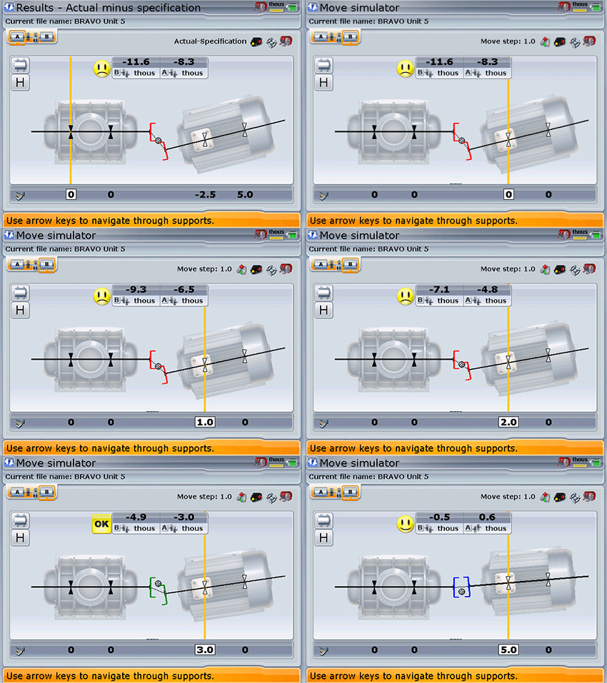
ROTALIGN® ULTRA will always suggest the ideal move, but in the real world, as we all know, that’s rarely how things work out. It may tell you to shim an impossible amount (say by asking you to remove more shims than what you have under the foot) or require a horizontal move in a direction you are bolt-bound in. Maybe you have an alternative idea of how to achieve the alignment and want to test what the outcome will be. These theoretical moves can easily be tested using the Move Simulator in the ROTALIGN ULTRA, without actually having to move the machines! Simply input the shim amount you want to try at each foot or the horizontal move you want to test. You will instantly see the outcome. On systems without the Move Simulator feature, input your proposed corrections as thermal growth values and return to the results screen. Your results screen will now show what would happen if those corrections were effected. If you opt for the second option, be sure to remove the fictitious thermal growth values before taking more readings and actually performing corrections.
by Tyler Wulterkens CRL
Good condition monitoring software will have capabilities that allow importing of critical process data into the CM database. Information such as temperatures, pressures, equipment speed, etc., are very important to the vibration analyst or other CM analyst. This information provides additional parameters to help the analyst understand and confirm the results uncovered during their analysis.
by Trent Phillips
The most important thing that can be said about securely mounting bracketing is this: Whatever you attach the bracket to MUST be rigid to the shaft when you are not attaching to the shaft itself. When the bracket is secured and the laser/emitter is attached to it, rotating the shaft causes the bracket to rotate along with the laser like the spoke of a wheel. Regardless of the laser’s distance from the shaft centerline, as long as everything is tight, the invisible circle that the laser traces as it is rotated has the same rotational centerline as the shaft. Make sure that everything is tight.
by Ana Maria Delgado, CRL
When a facility goes into a planned outage, many events needed to happen before the company gets to this point.
The following are some interesting facts and activities a plant will undergo before an outage:
• Planning for a major outage begins when the previous outage is completed.
• Planning and scheduling play a major role. Prioritizing which jobs need to be completed, and in which order, and obtaining the necessary permits and work orders.
• Most of the maintenance budget of a facility is spent on outages. With proper planning and scheduling, costs can be reduced, rather than reacting to imminent problems.
• Several factors dictate when an outage will take place: Weather, the flow of incoming raw material, demand for product/service, consensus with the local utility, cost, and manpower.
• Preparing or ordering auxiliary equipment and/or replacement components. Identifying lead times helps with scheduling.
• Preparing scaffolding permits and crew will help indicate the length of the outage.
• In most cases, operations will control the work, and maintenance performs it.
• Determining the need for contract work, and in-house work. This will identify the available manpower and labor hours.
• Scheduling visits from manufacturer’s representative for critical equipment. This will help with warranty issues, and ordering necessary components.
• Safety programs and procedures must be implemented.
• Implementing an RCM program may help more planned work and fewer unexpected outages.
• Identify how many shifts will work during the outage, and hire the proper crew.
by Adam Stredel CRL