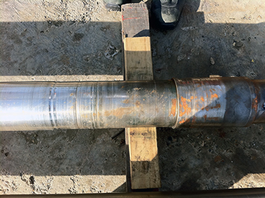
Vertical turbine pumps need frequent alignments of their guide bearings. The result of not performing the proper alignment can be seen in the image above. In some cases when maintenance disassembles a pump the damage to the shaft is so substantial, that the entire shaft needs to be replaced. This problem translates into more costly maintenance and longer downtimes. Adding bore alignment into the maintenance procedure will increase the life of the pump as well as a reducing the frequency of unscheduled maintenance.
by Carlos Bienes CRL
Too often management remembers the unanticipated machine failure of three years ago rather than the dozens of prevented failures that did not occur since that event. The challenge to maintenance and reliability teams is how to keep their successes at the forefront of management’s mind. I have visited a large number of plants and factories over the years and one of the most effective tools I have ever seen is a trophy case. These display cases are most often located in hallways where plant personnel walking by can see the displayed saves. Often they will show a cut-away of a bearing or gear showing slight damage. The background often includes graphics indicating the amount of saved production time or saved cost when compared to breakdown maintenance.
One paper mill had a cutaway of two bearing raceways that both appeared to be normal. The accompanying background included pictures of the raceways taken with a stereomicroscope. It showed a magnified picture of the good bearing in contrast to the bad bearing, which had looked good to the naked eye. The differences in the pictures were striking. The message was, that we know what we are doing and this is real science, not guesswork, thereby proving that we provide value. Displaying your SUCCESS stories where everyone can see them will help paint a positive and progressive image of your reliability team. When they think of your program, they should think of SUCCESS!
by Greg Lee
One thing that most field vibration analysts will become aware of is how the directional stiffness of a typical machine will manifest itself in vibration data. The typical horizontal machine train (driver and driven) is fastened down to a very rigid foundation, having little to no freedom of movement in the vertical plane. Although the machine components are bolted and welded to one another in the horizontal plane, there is nothing like the rigidity of the foundation preventing the movement of the machine frame in the horizontal plane. This being the case for most horizontal machine trains the vibration amplitude in the horizontal direction is typically higher than in the vertical direction. How much higher depends on the structural make-up of the machine. This is a tipoff to the savvy analyst who may notice a rise in the ratio of the vertical amplitude to the horizontal. When this happens, it usually means the machine has lost some stiffness in the vertical direction. This can be due to loose fasteners, cracked welds, or even compromised foundations.
by Mike Fitch CRL
Is your equipment considered a slow-running speed machine? If so, what speed do you consider slow? Is it 30 RPM? 60 RPM? 100? 200? 600?
No matter what you consider slow speed, the two most critical points to consider for slow running equipment are:
1) Does your vibration sensor (accelerometer) have the appropriate frequency range to measure low frequencies?
2) Does your vibration analyzer and/or online monitoring system measure down to those frequencies?
Unfortunately, some vibration analysis devices on the market are not truly capable of measuring slow-speed equipment and providing a true mechanical diagnostic analysis. These devices can actually create a reactive maintenance result that the device was supposed to prevent.
For example, a motor shop in South Texas had completed a rebuild of a 100 HP motor. The motor is used in the oil and gas industry. It has an average running speed of 30 RPM. The customer tested the motor on their motor test stand. As it was in its test cycle, the vibration was measured using a self-diagnostic vibration analyzer. The results and diagnostics the analyzer provided to the customer were “please replace bearing”. After several further tests running the motor on the test stand, the customer refused to accept those results and retested the motor using a VIBXPERT® II analyzer with machine templates designed for slow running machinery and a VIB 6.147 low-frequency accelerometer.
The final analysis revealed a high unbalance condition on the motor (11 mils peak-peak). The motor shop followed up with a balancing job (single plane) on the motor. The balancing was performed with the VIBXPERT II as well. Subsequent tests showed that the unacceptable low-frequency amplitude that had been observed (11 mils pk-pk) prior to performing the balance job had now disappeared. Final mechanical diagnostics showed no problems and the bearings were in proper condition. A balance report was printed and the motor was ready to leave the shop.
If you want to increase your uptime and availability and reach your financial goals, proper investment in Condition Monitoring and reliability will provide a positive return on your investment.
by Alex Nino CRL
A lot of maintenance employees believe that small machine trains can be precision aligned more quickly and easily than larger machine trains. This is not always the case! Smaller machine trains are usually less rigid. This can cause the alignment to shift as the anchor bolts are tightened. Almost all small machine trains have some form of soft foot condition that must be corrected because the machine bases are often not flat or of inferior construction. Additionally, thermal growth can have a large impact on smaller machine trains as well.
Don’t be fooled by the size of the equipment you must precision align. It is critical to understand how the size, design, operation, and other factors affect the equipment you must align.
by Trent Phillips
Every vibration analyst relies on accurate data to provide the necessary information to base a report or work order on that will set in motion the activities of the maintenance department. Therefore, the analyst must resist sinking into bad data collection habits. When early detection of a fault or possible problem is important (it usually is), the measurement contact point for a walk-around route should be clean down to the bare metal. A nice thick coat of paint is good at protecting against rust, but it’s not very good for transmitting vibration.
Trends are a very reliable tool for monitoring the condition of equipment IF the data points are taken exactly the same way time after time. The analyst must make sure that the amplitude and frequency changes are equipment-induced and not an analyst- or monitoring apparatus-induced. Sensor placement points should be clearly marked.
Many analysts take thousands of points each month and often don’t see the same discrete point again for at least a month. Don’t depend on memory to place your sensor.
Don’t play data roulette; force yourself into good data collection habits. The day will inevitably come when something seems to be wrong with your data and you will have to troubleshoot where the problem is. If you have disciplined yourself into meticulous habits, the troubleshooting will be much easier, and you can be much more confident in your day-to-day analysis.
by Mike Fitch CRL
Severity determination is one of the most difficult tasks a vibration analyst faces. Several methods can be used to help identify the severity of defects identified in vibration data.
One method is to consider the amplitude of the defect. This usually works well but does not always correctly identify the severity of the problem. Another method is to look at the G swing (peak-peak value) in the time waveform data that has been collected. An additional method is to trend the data and look for increases in trend values between data collection intervals. The rate of change shown in the trend data can be a very good indicator of the progression of the identified defect.
A combination of methods usually works best to help identify the severity of a defect. However, it is always best to report the defect condition for repair as soon as it has been identified. This provides as much time as possible to properly plan and schedule repairs as may be required.
by Trent Phillips
Right angle drives or 90-degree gearboxes are very common in the industry. These are speed reducer/increaser machines with an output shaft exiting at a 90-degree angle with respect to the input shaft. In some cases, the 90-degree turn stays on the horizontal plane. This is great because the alignment can be treated as a machine train alignment.
However, when a gearbox has an output shaft emerging vertically, the alignment becomes much more complex. This coupling should be treated as a vertical alignment, where the support of the machine is a flange, whose feet are visualized as being the flange bolt pattern where shimming takes place to correct angular misalignment. This fictitious flange is to be placed at the plane of the feet, where the shims are to be inserted or removed. Having a system that will allow you to customize the bolt pattern and bolt positions is critical in this case. Depending on the existing conditions at the gearbox feet, you may wish to choose a positive, negative, or optimized (+/–) shimming solution in order to minimize the axial effect of any shimming corrections. Offset corrections are performed by moving the machine laterally only after angularity has been corrected.
What if the shaft is not in the center of the machine but offset to one side? With the proper laser alignment system, the user can set up the alignment job so that the true shaft geometry within the machine frame is correctly represented. Only in this way can we obtain the proper corrections at the machine’s feet.

by Adam Stredel CRL
When performing an alignment on a machine train with a motor fitted with a sleeve bearing, it is important to account for the magnetic center of the motor. Failure to do so can cause excessive vibration and premature failure of motor components and the shaft coupling.
If the motor has recently been rebuilt it should come from the motor shop with a magnetic centerline scribed on the shaft. To properly set the shaft coupling gap do the following:
- Determine the correct coupling gap based on the manufacturer’s recommendation. (Note we refer here to the proper installation gap size and its tolerance, not the alignment gap tolerances for angularity.)• Identify the correct scribe mark on the shaft that represents the magnetic center.
- Measure the distance between the scribed mark and the outside bearing housing lip. In the case that the magnetic center scribe mark falls inside the motor housing while at rest, scribe a mark in the rest position.
- While the machine is un-coupled run the motor and estimate the difference between the newly scribed mark and the magnetic center mark. This is the distance that will need to be compensated for when setting the coupling gap.
- Set the coupling gap according to the manufacturer’s recommendation minus the distance measured for the magnet center correction if the mark is outside the bearing housing. Add the difference if the mark is inside the bearing housing. This will provide the proper coupling gap under the normal running condition.
by Ana Maria Delgado, CRL
The Hibbing Taconite Company, managed by Cliffs Natural Resources of Hibbing, MN, won UPTIME Magazine’s Best Lubrication Program award. At the heart of their condition monitoring efforts is the Oil Analysis component of their lubrication program, key to helping them identify problems at an early stage of failure.
During the first phase of the program, which they called “First Evolution”, reliability engineers were trained as Level I Machine Lubrication Technicians (MLT1). Thereafter, dedicated lubrication mechanics were assigned to the plants to monitor the condition of the oil. They engaged with their vendors to identify needed parts and reviewed their planning, scheduling, and work execution. They selected critical equipment on which to prove the concept.
During Phase 2, MLT1 training continued, including lubrication mechanics and supervisors. Critical equipment underwent lubrication upgrades with the addition of desiccant breathers, sight tubes, sample ports, and quick couplers for filtering, allowing for safer filter changes and reducing cross-contamination risk.
Today, 80 employees have been MLT1 trained on machinery lubrication and basic oil analysis. Employees are fully engaged and enjoy wholehearted management support as significant consumption reduction was realized. Management views the program as an investment.
During their presentation at the IMC-2012 International Maintenance Conference, Reliability Engineer Dan Lerick shared that in certain applications, they have proved a 3.5% energy reduction by switching to synthetic gear oil, which also extended oil drains from 5 to 15 years. Another positive was the switch to synthetic engine oil where they observed a reduction in fuel usage and fueling time, with an extension in engine life and extended drain and maintenance intervals. Overall ROI was under 1 year!
In addition to their award-winning Lubrication Program and as part of their reliability efforts, the company uses CMMS software and other Predictive Maintenance technologies such as Ultrasonic examination, Laser Alignment with ROTALIGN ULTRA, etc. Learn more.
Congratulations to Dan Lerick and his team for this award and a job well done!
Program Highlights
1) Fluid Analysis consolidated across all Cliff operations. They now use a single oil lab after carefully ranking and comparing sample results from eight different labs. The benefit was consistency and the ability to review and compare data.
2) For Fluid Sampling, they developed sample standards per equipment specs, installed sample ports, and trained personnel on how to collect samples. Their CMMS system controls their sample frequency.
3) The use of Grease Systems and Grease Routes wherever possible along with ultrasonic technology on motors.
4) Implementation of condition monitoring (CM) via oil moisture sensors and CM sensors for real-time monitoring. The immediate benefit was a reduction in overall site oil consumption by removing water contamination.
5) Cleaner and safer fluid changes with the use of dedicated Lube Carts to eliminate drips and spills.
6) All machines were tagged with machine identification and lubrication information to reduce mixing and cross-contamination.
by Ana Maria Delgado, CRL
Ultrasound instruments listen for high-frequency sounds that are not heard in the range of normal human hearing. Typical applications include compressed air & gas leak detection, electrical inspection, and condition monitoring applications.
Ultrasound technology can easily be implemented into established maintenance & reliability programs that are currently using other technologies such as vibration analysis & infrared. The best M&R programs are ones that do not rely on one single technology but on multiple technologies. Here are some tips to assist you:
Best Practices for Mechanical Inspection
• Initial ultrasound data should include both decibel readings and sound files
• Once baseline has been established, decibel readings are recorded
• Set alarm levels
• Record both decibel readings and sound files when an alarm is reached
Best Practices for Electrical Inspection
• Infrared scans are typically done by an outside service provider annually, or semiannually. In between annual infrared scans, use ultrasound to periodically listen for conditions.
• Only relying on infrared increases the chances of missing conditions not detected by infrared
• The best method of diagnosing electrical issues with ultrasound is through the use of recorded ultrasounds
Thanks to Adrian Messer with UE Systems, Inc. for sharing these tips with us.
by Ana Maria Delgado, CRL
Condition tasks such as vibration monitoring, oil analysis, thermography, ultrasound, motor testing, and other methods should be used to identify failure conditions that can result in functional failures in your equipment. Collaboration of data between these technologies facilitates machinery fault diagnosis.
Proactive techniques like those referenced above require an investment in technology, training, labor, implementation, and maintaining the activity. However, this investment will pay continual returns through improvements in maintenance planning and scheduling, reliability, reduced costs, and reduced risks.
Identification and correction of failure conditions before a functional failure occurs in machinery has proven to be more cost-effective and provide reduced financial risks versus a reactive maintenance program which instead applies a run to failure approach.
by Ana Maria Delgado, CRL
It is a good idea to ask your equipment repair providers or equipment suppliers to ensure that the vibration levels of the equipment they supply meet your standards. Once your facility takes ownership of the equipment from the supplier or repair provider, the responsibility for any repairs usually becomes yours. This means any failure modes (bearing defects, misalignment, unbalance, resonance, etc.) are the responsibility of your facility to repair.
This creates additional costs and reduced reliability.
You can include vibration acceptance criteria and other standards in the purchase order that is issued. This way you can hold the repair provider or supplier accountable for any bad practice repairs or bad practice installation methods they may use on your equipment.
by Trent Phillips
Often, seal failures are not the cause of an incorrect installation or the wrong seal type for the product being pumped, but a symptom of misalignment. If a seal starts dripping or misting product within days after installation, or suffers a “catastrophic” failure within weeks of being placed in service, the first suspect should not be the seal vendor or the technician installing the seal; misalignment should be considered as a good candidate for the cause of failure. Visualize a typical pump-motor system of bearings, shafts, seals, and coupling. The weakest link in the chain is usually the mechanical seal. In the last ten years, seal technology has progressed substantially in both material composition and design (most notably cartridge seals), in compensating for shaft vibration.
However, significant misalignment can still overwhelm the ability of a seal to keep both seal faces pressed firmly together or to withstand seal face cracking.
So remember, the next seal failure you encounter, quickly check misalignment with a good laser alignment system to see if the weakest link has failed due to misalignment.
by Ana Maria Delgado, CRL
Every vibration analyst knows that our failures are quickly publicized throughout the facility or corporation. It is amazing how quickly this type of information is transmitted. This is why most analysts develop a very thick skin or soon find another career path.
It is important to make sure that your successes are publicized as well. Management should support this effort to increase the awareness of the Condition Monitoring (CM) efforts in your facility. Save the bearings and other items that are removed from the equipment as a result of your CM efforts. Keep some of these items around your office to do a “show and tell” when people visit you to criticize your efforts. Consider creating a monthly or quarterly email or newsletter demonstrating your successes. Publicize your findings in an article or present the findings at a trade show. Be creative, but make sure that others are aware of the value that you and the CM technologies you utilize provide. Otherwise, you may find yourself and/or the CM group on the chopping block.
by Trent Phillips
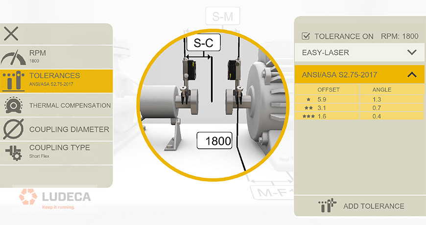
There are several ways of looking at alignment tolerances, including standard versus vector tolerances, as well as sliding velocity tolerances. The most used are standard tolerances, but which are applied differently for short flex versus spacer couplings. The best laser shaft alignment systems will allow you not only to select tolerance types but also coupling types. For standard tolerances, keep in mind that the vast majority of true flexible couplings (such as gear, grid, elastomer element, or diaphragm type) have two separate flex planes. So do all spacer couplings. The difference between short flex and spool piece, spacer, or jackshaft couplings lies in the distance between these flex planes. Any time the distance between flex planes is greater than the diameter of the working flex plane, you are better off calling it a spacer rather than a short flex, from the perspective of achieving satisfactory alignment.
Keep this in mind when selecting coupling type, as it will greatly increase the alignability of the machines, and ease your job in the field. For a deeper understanding of the subtleties involved in these issues, it is recommended to attend an in-depth training course in laser alignment.
Check out the Easy-Laser XT Series, the only laser alignment platform on the market today with the new ANSI alignment tolerances built-in giving the user the freedom to choose between traditional tolerances, the new ANSI standards, or custom tolerances of the user’s own choosing.
by Ana Maria Delgado, CRL
Do you verify the quality of the maintenance work or installation that is completed on your equipment? You may be surprised to know that failure modes such as bearing defects, misalignment, etc., can be introduced into your equipment as a result of poor maintenance practices or installation work.
Condition Monitoring (CM) follow-up measurements should be completed after each maintenance repair on your machinery. This will allow you to verify that the equipment was repaired correctly and that no other failure modes were induced as a result of the repair effort or installation of the equipment.
It is a good idea to make CM follow-up measurements a part of the work order. This way the work order cannot be closed until a follow-up measurement with the CM technology (vibration analysis, oil analysis, ultrasonics, motor diagnostics, thermography, etc.) has been completed. This will help you ensure that your equipment was repaired correctly, installed correctly, and is truly ready for operation. This results in improved equipment reliability.
by Trent Phillips
When performing a multiple belt-sheave alignment, it is imperative that all the belts and belt grooves are inspected individually for wear. If any of the belts are slipping, then all belts must be replaced at the same time. To achieve an accurate alignment between the pulleys one can use a machinist’s straightedge, or place a tightly drawn piece of string, across the faces of the sheaves to see if all four points of contact are made or you can utilize a Laser Pulley Alignment tool. Regardless of which system is used to perform the alignment, it is a good practice to monitor any changes in angularity and/or offset in the sheaves as the hold-down bolts of the machine to be moved are being tightened during the belt tensioning procedure, since this will allow the sheave alignment to be maintained true.
by Ana Maria Delgado, CRL
Many end users have taken laser alignment equipment and “checked” alignments on equipment that has been running satisfactorily, and very often with vibration data that falls well within alarm thresholds, only to find the alignment out of normal alignment tolerances. In this instance, the vibration data should be the determining factor. If the equipment is running well, leave it alone. It would however be a very good practice to keep this alignment data and use it in the future for the intentional misalignment of this particular machine. It is quite possible that the machine had in fact been deliberately misaligned when cold and stopped to compensate for positional changes that occur due to thermal growth or dynamic load shifts.
by Ana Maria Delgado, CRL
The health of your equipment is critical to your company’s success. Asset health reporting is an excellent way to understand and convey the current health of your equipment in a very meaningful way.
If a condition monitoring (CM) technology identifies a failure condition on a machine, then the asset health of the machine is usually flagged and considered “Red” to alert operators and management that the health of the machine is compromised. Multiple CM technologies may identify the same failure condition on the machine and this can be identified in the Asset Health report as well. This information can be used to convey a sense of severity. Also, the information can be used to easily alert other individuals (other CM Analysts, the Reliability Engineer, the Planning and Scheduling Group, Management, etc.) that the machine is in an unhealthy condition and that maintenance effort should be directed toward the machine.
by Trent Phillips