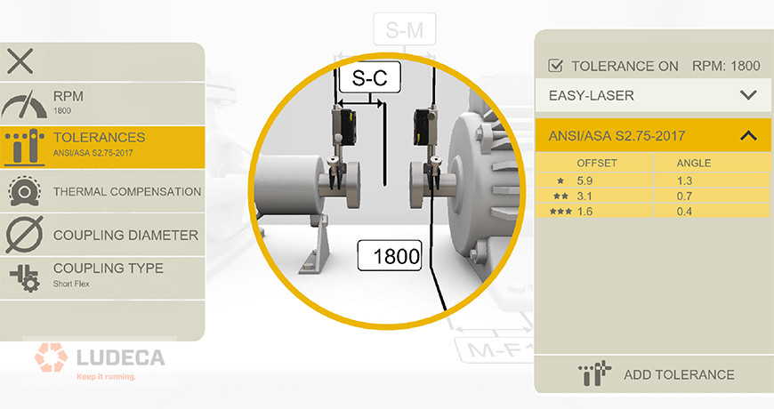
There are several ways of looking at alignment tolerances, including standard versus vector tolerances, as well as sliding velocity tolerances. The most used are standard tolerances, but which are applied differently for short flex versus spacer couplings. The best laser shaft alignment systems will allow you not only to select tolerance types but also coupling types. For standard tolerances, keep in mind that the vast majority of true flexible couplings (such as gear, grid, elastomer element, or diaphragm type) have two separate flex planes. So do all spacer couplings. The difference between short flex and spool piece, spacer, or jackshaft couplings lies in the distance between these flex planes. Any time the distance between flex planes is greater than the diameter of the working flex plane, you are better off calling it a spacer rather than a short flex, from the perspective of achieving satisfactory alignment.
Keep this in mind when selecting coupling type, as it will greatly increase the alignability of the machines, and ease your job in the field. For a deeper understanding of the subtleties involved in these issues, it is recommended to attend an in-depth training course in laser alignment.
Check out the Easy-Laser XT Series, the only laser alignment platform on the market today with the new ANSI alignment tolerances built-in giving the user the freedom to choose between traditional tolerances, the new ANSI standards, or custom tolerances of the user’s own choosing.
by Ana Maria Delgado, CRL
Do you verify the quality of the maintenance work or installation that is completed on your equipment? You may be surprised to know that failure modes such as bearing defects, misalignment, etc., can be introduced into your equipment as a result of poor maintenance practices or installation work.
Condition Monitoring (CM) follow-up measurements should be completed after each maintenance repair on your machinery. This will allow you to verify that the equipment was repaired correctly and that no other failure modes were induced as a result of the repair effort or installation of the equipment.
It is a good idea to make CM follow-up measurements a part of the work order. This way the work order cannot be closed until a follow-up measurement with the CM technology (vibration analysis, oil analysis, ultrasonics, motor diagnostics, thermography, etc.) has been completed. This will help you ensure that your equipment was repaired correctly, installed correctly, and is truly ready for operation. This results in improved equipment reliability.
by Trent Phillips
When performing a multiple belt-sheave alignment, it is imperative that all the belts and belt grooves are inspected individually for wear. If any of the belts are slipping, then all belts must be replaced at the same time. To achieve an accurate alignment between the pulleys one can use a machinist’s straightedge, or place a tightly drawn piece of string, across the faces of the sheaves to see if all four points of contact are made or you can utilize a Laser Pulley Alignment tool. Regardless of which system is used to perform the alignment, it is a good practice to monitor any changes in angularity and/or offset in the sheaves as the hold-down bolts of the machine to be moved are being tightened during the belt tensioning procedure, since this will allow the sheave alignment to be maintained true.
by Ana Maria Delgado, CRL
Many end users have taken laser alignment equipment and “checked” alignments on equipment that has been running satisfactorily, and very often with vibration data that falls well within alarm thresholds, only to find the alignment out of normal alignment tolerances. In this instance, the vibration data should be the determining factor. If the equipment is running well, leave it alone. It would however be a very good practice to keep this alignment data and use it in the future for the intentional misalignment of this particular machine. It is quite possible that the machine had in fact been deliberately misaligned when cold and stopped to compensate for positional changes that occur due to thermal growth or dynamic load shifts.
by Ana Maria Delgado, CRL
The health of your equipment is critical to your company’s success. Asset health reporting is an excellent way to understand and convey the current health of your equipment in a very meaningful way.
If a condition monitoring (CM) technology identifies a failure condition on a machine, then the asset health of the machine is usually flagged and considered “Red” to alert operators and management that the health of the machine is compromised. Multiple CM technologies may identify the same failure condition on the machine and this can be identified in the Asset Health report as well. This information can be used to convey a sense of severity. Also, the information can be used to easily alert other individuals (other CM Analysts, the Reliability Engineer, the Planning and Scheduling Group, Management, etc.) that the machine is in an unhealthy condition and that maintenance effort should be directed toward the machine.
by Trent Phillips
Laser shaft alignment has become ubiquitous these days. And for the most part, alignments are very similar from one machine train to another. The user enters the RPM for tolerance evaluation, enters the dimensions of the driver, measures misalignment, and makes corrections. But what happens when an unusual physical configuration exists, as when the foot of the machine is between the flex planes of the coupling? Or the receiver cannot be mounted outboard of the flex planes of such coupling?
Entering a dimension correctly as a negative value can take care of that problem. This will ensure that the corrections at the feet are precise, and the alignment is done properly.


Does your laser alignment system have this crucial capability? Our ROTALIGN® ULTRA laser alignment system does!
by Adam Stredel CRL
Do your analysts use consistent phrases or statements when creating condition monitoring (CM) work orders? It is very important to convey concise and accurate information with each CM work order. Often times misspelled words, inaccurate information, or incomplete maintenance steps are included in work orders. A best practice is to determine the most common findings for a specific CM technology and determine what actions should be taken as a result. For example, if vibration analysis identifies unbalance in a fan, a recommendation should be made to clean the fan prior to attempting to balance it. If a CM technology identifies a failure that requires the machine to be removed, then re-alignment may be necessary before the machine is placed back into service. All of these steps and perhaps additional steps should be conveyed by the CM analyst creating the work order.
Creating consistent and detailed steps for common CM problems will avoid forgetting to convey important information to those doing the work. This will help ensure that best practice maintenance is completed on your equipment, things are not forgotten, misspelled words entered, or other common mistakes made.
by Trent Phillips
When dealing with a gearbox that has 3 feet, there are two possibilities:
a) If the feet are located under the shaft and bearing housings, view the gearbox as a normal 4-foot machine. This will give you inboard and outboard corrections for the feet. The end that has the 2 feet should be corrected evenly, and the 3rd foot should be corrected as per the screen.
b) If the feet are on the sides of the gearbox, or NOT under that shaft or bearing housings, then configure the gearbox as a 6-foot machine. This will give you corrections for the inboard, middle and outboard feet. Correct accordingly at each foot.
by Ana Maria Delgado, CRL
In any alignment situation, one of the most basic principles is rise over run. Think of it as a change in offset over a distance. It is also a way to quantify angles without using degrees. When the laser system measures “angularity”, it expresses it as rise over run, or a change in offset over a distance. This information, along with the dimensions that the user enters is what the system uses to calculate corrections at the feet. That is why it is very important that laser measurements are repeatable and that all dimensions should be accurate to within 1/8 inch. The sensor to coupling dimension is the most critical of these. If the laser measurements are good but the dimensions for the feet are not, any corrections the computer calculates will not work due to the fact that they are “applied” to a different location, not at the actual foot location. If you are making the corrections that the computer says to and your alignment is still off, double check your dimensions.
by Ana Maria Delgado, CRL
Many facilities have placed overall vibration data collection devices in the hands of their operators. The goal is to give the operators and production a tool to help identify equipment problems and the severity of those problems.
The intent of this effort is very good. However, the true value of this effort is usually not understood.
First, generic overall vibration levels can be quite dangerous if not fully understood. Secondly, the actual value of having operators collect vibration data is not usually taken advantage of fully.
Overall vibration levels require the same amount of time for data collection as is required to collect very detailed vibration information on the equipment. Therefore, the operator should actually collect the overall vibration levels they need while simultaneously collecting detailed information for the vibration analyst to review. What happens if the operator collects an overall vibration level on a machine and some problem is suspected? The facility has to invest time and effort for an analyst to revisit the machine and collect enough vibration data to actually verify and analyze the problem. This means that additional labor is required or the results are diminished. With the correct vibration hardware, the operator can easily collect the overall vibration values they need as well as the detailed information the analyst needs. This saves time and money. What if the activity occurs after hours? The detailed data collected by the operator could be remotely passed on to the analyst for detailed evaluation. This saves time and greatly improves the response time from employees and the technologies. Operators could be used to easily and routinely collect vibration data on much of the equipment for analysis by the vibration group. This would allow greater equipment coverage by the vibration analysis program, allow the analyst to focus on analysis, and spend less time collecting data.
To summarize, having the operator collect vibration data can be of great value if done the correct way, otherwise, the process can provide inaccurate information and reduced benefits.
by Trent Phillips
Many plants have routine morning and weekly meetings to discuss equipment issues or upcoming repairs that could affect production or maintenance activities in the facility. Are your condition monitoring (CM) and reliability efforts represented in these meetings? Failure to have representation of your CM and reliability efforts in these meetings means that important information will not be conveyed to the individuals in the plant that need it most.
Your CM Manager or Reliability Engineer may have critical information to share about the health of the equipment being discussed in these meetings. Additionally, they need to be fully aware of what is happening in the facility and how their efforts may be affected.
by Trent Phillips
Setting the proper LOR is essential to be able to separate closely spaced defect frequencies. An example would be a pump with 5 vanes that could generate a “Vane Pass” frequency equal to the number of vanes, or 5 times rotational speed; if the impeller end of the pump had an SKF 7301BEP bearing, it could have an inner race defect frequency of 4.99 times running speed. This combination would require a relatively high resolution or LOR in order to have enough detail to separate the defect frequencies of each defect.
by Gary James CRL
Overall values are the most common measurements and calculations used in vibration analysis. The purpose of this measurement and calculation is to identify changes in the condition of the equipment being measured.
Overall measurements are an important tool for the vibration analyst. However, generic overall values can actually be deceptive if their limitations are not fully understood. Typically, overall vibration values are measured and a calculation based upon the entire frequency range is measured with the vibration data collector.
It is possible for certain frequencies to increase while other frequencies decrease. This is important because these changes are indications of specific machine conditions. The overall value could actually decrease or change very little and give a false indication of the machine’s health.
Band alarms and band analysis is the best vibration method to indicate changes in the condition of your equipment. Specific bands can be easily created, measured, and trended around the specific failure modes in the equipment such as bearings, misalignment, unbalance, and many more. This type of information can alert you much more accurately of failure conditions in your equipment versus generic overall measurements and calculations.
by Trent Phillips
When machines are set in place, aligned, and buttoned down, it becomes too easy to forget about the gear couplings that may be used to transmit power between the machines. Gear couplings are tough workhorses that perform well in many applications because they operate quietly and efficiently. Since they are so reliable, we tend to take them for granted, forgetting about them unless trouble develops. Many times problems do occur simply because of neglect. Faults can usually be eliminated by keeping the shafts properly aligned and ensuring that the coupling lubricant is in good condition. Remember the old adage, “The right time to put in new lubricant is while the old lubricant is still good”. Open, inspect, and re-lubricate gear couplings every six months. If they operate in harsh conditions such as high ambient temperatures, they may need to be re-lubricated more frequently. On opening the coupling, a close inspection of the lubricant will tell if the re-lubrication interval is too long. Adjust the interval accordingly, and be sure to use a lubricant specified for gear couplings. Also, make sure you do not over-lubricate. Pumping away with the grease gun until the lubricant oozes out past the containment o-ring is just as harmful as having too little lubricant. Finally, it is imperative that the lubricant fits the application and operating environment.
by Ana Maria Delgado, CRL
Information Technology (IT) is a critical business function and is involved in almost every job function within a company. IT departments and their employees are often viewed as making our jobs more difficult or impossible to complete. Why does this happen? IT departments have the responsibility to provide tools (computers, software, systems, etc.) that create and manage critical business information. The responsibility to maintain, secure, and store this information falls upon them as well. They have to do this based on the standards set forth by the company.
If your company is about to implement a vibration analysis program or any other condition monitoring technology do not wait until the selection process has been completed to notify and involve your IT department. This could be creating a disaster situation between your department and IT within your company. It is critical to involve your IT department from the start of the selection process. This will help ensure that security requirements, computer requirements, and other critical things are taken into consideration before conflicts are created. You may actually find that your IT department can help you in your decision process, while avoiding conflict, saving time and money. Make IT an ally instead of an enemy!
by Trent Phillips
One of the most overlooked features of a good vibration data collector is the ability to enter important process information such as temperatures, pressures, equipment lubrication levels, equipment speed, and much more.
Documentation of process data is important for your production department. This information is important to the Condition Monitoring (CM) Analyst as well. Changes in process data may explain why the vibration amplitude levels or other CM conditions have changed.
Many facilities struggle with the ability to record and store process-related data. A good vibration data collector will have the ability to record and store this type of information. In fact, routes can be created for operators to guide them through the routine acquisition of this information. Vibration data can be acquired by the operators as well. This could provide additional value-added time in your facility.
This data can be easily stored to meet the documentation requirements of your facility and trended to provide increased analysis opportunities that may otherwise go overlooked.
by Trent Phillips
Our training partners at Pioneer Engineering have created a few tips your organization can implement aimed at cutting costs without sacrificing quality and productivity.
Tip #1: Establish a Reliability Centered Maintenance Program
- A well-established Reliability Centered Maintenance Program helps identify correct maintenance tasks to increase the reliability of the assets and cut costs by eliminating unnecessary PM tasks.
- Reliability Centered Maintenance Programs assist in clarifying maintenance responsibility and prevent costly unplanned downtime.
Tip #2: Perform a Criticality Assessment of all Assets
- Criticality Assessments will determine which components are critical to an operation’s efficiency and should receive the focus.
- Criticality Assessments quantify safety, environmental, operation, and repair cost consequences in the event of a functional failure.
- Perform Criticality Assessments on your spare inventory. Do you have the correct spares and quantity of spares in stock? Do you have unnecessary spares in stock that take up warehouse space and tie up capital that could be used elsewhere?
Tip #3: Avoid Costly Repairs by Analyzing Vibration Data on a Consistent Basis
- The consistent analysis allows the ability to monitor trends and detect problems before catastrophic failure occurs.
- Consistent analysis and trending allow flexibility in scheduling maintenance and reduced maintenance costs by preventing unscheduled downtime.
Tip #4: Avoid Fixing Repeat Offenders by Completion of Root Cause Failure Analysis
- Root Cause Failure Analysis will determine the underlying problem causing the failure to determine the best course of action
- Many failures are caused by operational issues instead of equipment or maintenance issues. A minor process adjustment may increase reliability and reduce costs.
Tip #5: Ask Questions
- Vibration analysis and other PdM technologies can help identify a potential issue but sometimes can be difficult to understand. Do not be afraid to seek expert guidance when potential issues are identified.
Need help improving and/or establishing a maintenance program in your company? Don’t hesitate to ask us how. We are here to help.
Thanks to the entire PIONEER ENGINEERING team for allowing us to share this article with you.
by Yolanda Lopez
Maintenance departments periodically schedule maintenance checks on their belt- or chain-driven equipment in order to confirm that a good alignment exists between the pulleys or sprockets, especially if evidence of premature wear on the belts or sprocket teeth is detected.
For this task a Dotline Laser, Sheavemaster or Sheavemaster Greenline laser pulley alignment tool is ideal. It indicates misalignment in all three degrees of freedom (axial offset, horizontal angularity, and twist angle) instantly.
Always mount your laser pulley alignment tool on the smaller pulley and the targets on the larger one, for maximum resolution. Ensure that the mounting surfaces (pulley faces) are free of dirt or rust, and don’t forget to verify the proper tension of the belts (or chains) after the alignment.
Download Belt & Chain Storage Best Practices
by Mario Rostran CRL
A strobe lights is an inexpensive tool that every vibration analyst should have. Typically, strobes are used to determine the operational speed of equipment. However, a strobe can be used for many other troubleshooting activities. For example, coupling inspections can be completed to identify wear or other issues. The strobe can be set to a specific frequency to identify the source of an issue revealed by vibration analysis. Many other troubleshooting tasks can be easily completed using a strobe. Do not overlook the value this device offers.
by Trent Phillips
The safety strap which is included with the analyzer should be checked for condition prior to each use. Most safety straps use Velcro and the Velcro is there for your safety. The strap is designed to separate to prevent injury should your cables become tangled in the rotating shaft or some other moving part of the machine.
Replace the straps if the Velcro becomes dirty or no longer holds. Never glue, bolt, staple, or otherwise permanently affix a strap to the analyzer, because this could prevent the strap from functioning correctly and result in serious injury to you or a coworker.
by Gary James CRL