As Published by BIC Magazine December 2015 issue
A world-class reliability program is not achieved overnight, yet you must start somewhere. Your first step is to vest your entire human capital in its success. Reliability is a culture, not a goal, and it flows from the top down.
Therefore, executive sponsorship with integrity and enforcement is a must. Obtain buy-in to the culture of reliability from everybody in your organization, or the effort is doomed to fail. Start with this realization, and your reliability effort will ultimately succeed, and you and your stakeholders will reap its rewards.
The reliability workflow must be well organized and underpinned by a Computerized Maintenance Management System (CMMS). Let’s look at how it works in a world-class program.
Ultrasound analysis detects a bearing fault in a critical motor early in the P-F curve. The analyst enters this data in the CMMS and trends it. The analyst decides to request a work order with recommendations. This is Stage 1 in the work order process.
The work order is now reviewed by both maintenance and operations, thereby ensuring buy-in from operations as well. This is Stage 2. This review process ensures only truly needed or valuable work is approved. Also, older open work orders can be combined with this one to further streamline planned activity on the asset. For instance, an earlier work order was created to align the machine, but the work was never carried out, resulting in the bearing damage the ultrasound analyst has now detected. The review process would catch the older open order and add it to the present order. This would prevent the millwright from going out to align the machine tomorrow only to have a repair technician go out the following week and repair the motor but do no alignment on it. This review process tries to eliminate inefficiency, duplication, and detrimental work sequences.
Stage 3 assigns the work order to the maintenance planner for action. Only approved and truly necessary work enters the planner’s backlog. The planner ensures work is properly prioritized. Two things are needed: The criticality ranking of the asset (ascertained from systems’ criticality analysis) and its operational criticality. Both of these factors can be multiplied together to create a more accurate prioritization of the workflow. The planner creates a new work plan if needed and should consult with maintenance supervisors and technicians; valuable insights may be gained into what parts, tools, and equipment should be specified in the work plan. Next, the planner orders the maintenance, repair and operating materials (MRO) spares, and tooling required to complete the job and verifies the parts are available and kitted (best practice). The planner should not concern himself with scheduling.
Now on to Stage 4: assignment to the scheduler. The scheduler allocates the HR and necessary time to accomplish the task, with a cushion for unforeseen complications. He too should consult with the maintenance supervisor and technicians to obtain cooperation and buy-in to the schedule. Coordination with operations is crucial. Operations “owns” the equipment and must sign off on the schedule to bring the asset down.
Stage 5 assigns the order to the appropriate maintenance and electrical supervisors, who in turn assign specific tasks in the work plan to their respective repair technicians, electricians, and millwrights, and verify MRO spares has delivered the parts kit to the proper location.
Now the work order enters Stage 6: the work execution phase. Once the technicians have completed the work, they report to their supervisors, who return the asset to active duty status in the system. Operations is notified the asset is ready for service, and MRO spares is notified of any unused parts and supplies that should be returned and reintegrated into the MRO spares inventory. Technicians and supervisors should feed their observations and data into the CMMS system.
Stage 7 sees the ultrasound analyst performing follow-up data collection on the asset to ensure all is well. The work now goes back to the planner to be formally closed. This ensures all important data has been accumulated and distributed within the system, enabling key performance indicators to be updated.
As good data accumulates, reliability engineering will use it to improve the entire reliability and maintenance process, discover frequent failure patterns, identify training needs, drive out defects, streamline production and help to improve the design process. As the plant becomes more efficient and productive, greater resources can be allocated to defect elimination and strengthening condition-based maintenance technologies, further impelling the transition to a proactive, reliability-centered culture. Reliability is a never-ending journey of continuous improvement.
by Alan Luedeking CRL CMRP
Guest post by Jeff Shiver, Founder of People and Processes, Inc.
As a maintenance planning and scheduling professional, I am often asked how to schedule maintenance activities when production is 24/7 or 24/6. An important question is whether the 24/7 operation is driven in part by a lack of reliability or if the organization is proactive and actually capacity constrained. In either case, the challenge is finding windows for work with the equipment stopped or shut down.
- Failure to identify smaller windows for work
- Give work to operators
- Lack of partnership between the operations and maintenance group
- Get the work done right
- Make resources available
- The right focus on preventive maintenance (PM)
- Identify failure
- Act, don’t react
- Don’t defer PM tasks
- Failure to take advantage of unplanned downtime for proactive work
- Manage the backlog
- Lack of effective coordination between the crafts
For more details, please read the full article.
by Yolanda Lopez
A facility just replaced several 1,000 HP slurry pumps with a massive 4,000 HP slurry pump at a pumping station. As part of this project, Ludeca supplied a WEARSCANNER® particle counter that is installed on the oil return line just before the filter. This system reports partials per minute for different particle ranges and relays this data via Modbus to the process control computer. During the initial start-up, the particle counter showed particles passing through the counter with the worst range reporting 6 parts per minute in the 100 to 125-micron range. The startup oil was changed and the filter replaced. As a result, the particle count has now dropped to zero in all of the ranges.
by Greg Lee
A paper titled The Surprisingly Swift Decline of U.S. Manufacturing Employment by Justin Pierce suggests that the sharp decline in US manufacturing jobs as a result of imports from China. Regardless of the cause, it is a fact that US manufacturing has declined over the past several years. Along with the decline in jobs, there has been a decline in the technical skills needed for performing manufacturing jobs. The loss of technical skills is largely due to the fact that as manufacturing jobs declined, job training refocused to other areas such as service sector jobs.
This all happened at a time when the baby boomers who were the backbone of American manufacturing began leaving the workplace in droves due to retirement. The age of the baby boomers is rapidly coming to an end; and due to the decline in manufacturing, there’s been no concerted effort to replace them.
Download my entire UPTIME MAGAZINE article: Where Have All the Bearing Scrapers Gone?
by Bill Hillman CMRP
Now, more than ever flatness checks for main bearing bore alignment in reciprocating compressors are critical to bearing and crankshaft life. Ariel Compressors have a strict tolerance for the top rail alignment and the ER-82 document provided by Ariel discusses this in detail. There are many ways to perform a flatness check so long as the equipment meets the Ariel guideline for accuracy. Many people have chosen the INCLINEO® but the LEVALIGN® EXPERT adds a new dynamic in versatility.
In Midland, Texas, Shamrock Field Services performs these alignments with the LEVALIGN EXPERT. When checking a large frame like an Ariel JGZ the LEVALIGN EXPERT gives the user consistent, reproducible measurements they can trust to make critical adjustments. During a recent job in Odessa, Texas the Shamrock group used their ROTALIGN® ULTRA IS and LEVALIGN EXPERT to check both the coupling alignment and the top rail flatness of an electric drive motor and JGZ compressor in less than an hour. 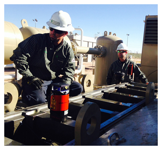
My experience is with both the INCLINEO and LEVALIGN EXPERT; let’s just say I am glad we purchased the right tool for the job. The LEVALIGN EXPERT is quick and very easy to operate. It cuts time and makes for a more proficient report. Hands down the LEVALIGN EXPERT is the way to go.” —Geoffrey Jameson, Shamrock Field Services
The initial setup of the LEVALIGN EXPERT for a top rail measurement is simple. Because the LEVALIGN EXPERT’s self-leveling laser adjusts to the surface plane automatically – the system can be put anywhere within line of sight for the rails to be measured. Either a magnetic plate or a tripod may be used to position the laser. Before placing the sensor on the rail via magnet, you want to make sure the rails are clean and clear of debris or excess oil. Once the rails have been cleaned the LEVALIGN EXPERT automated sensor is placed at the first point to be taken. The motorized sensor will lock into the laser and allow each point to be measured. Eight total points should be taken in no particular order.
I would recommend that if you are going to check the top rail of your compressor to use the LEVALIGN EXPERT, it will save time and headache in the long run.” —Dewayne Atwood, Shamrock Field Services
Taking measurements with the LEVALIGN EXPERT takes less than 5 minutes on JGZ and other large-scale compressors due to the freedom of a powerful Bluetooth. With the measurement data recorded, adjustments can be made by viewing the information in the rugged ROTALIGN ULTRA computer. Several options are available for scale, 3-D view or Table view. These numbers can be plugged into the ER-82 spreadsheet or used in the Alignment Center software. Reporting may also be done in the field through the USB option.
Versatility in many work environments is a key factor to the completion of a job and the ease of use with the LEVALIGN EXPERT sure outshines the INCLINEO.” —Robert Beck, Shamrock Field Services
Special thanks to the team at Shamrock Field Services, a gas compression service company, for sharing with us their success with our products.
by Matt Hadad CRL
Being a successful condition monitoring (CM) analyst requires qualities such as intelligence, dedication, a thick skin, willingness to help others, ability to focus, and more. Success in this profession is not easy. In fact, it can be argued that success is a constant struggle. The most successful CM analysts will have certain traits that are keys to their success; however, possibly the most important is the drive to “know” – to know what is causing that anomaly, defect, or early failure.
Read my entire article at PLANT SERVICES: Keys to Condition Monitoring Success
by Trent Phillips CRL CMRP - Novelis
One of the top priorities of any military organization is keeping soldiers fit for deployment upon demand. This usually involves exercises to maintain and increase job skills, physical abilities, overall health, and mental capabilities. Troops are encouraged and required to participate in activities that achieve these readiness goals.
Why should your organization and position be any different? What are you and your organization doing to ensure fitness for job deployment each day? Are your employees trained to function like F Troop or Seal Team Six?
Download my entire UPTIME MAGAZINE article: Is your Company Fit for Deployment?
by Trent Phillips CRL CMRP - Novelis
Happy to share two great articles by MAINTENANCE TECHNOLOGY Magazine about The Importance of Shaft Alignment and Precision Shaft Alignment For Improved Uptime:
by Ana Maria Delgado, CRL
PUMPS & SYSTEMS • September 2014
Revisiting the fundamentals of data examination, time and resolution can solve equipment issues before they happen.
Inexperienced vibration analysts encounter a common problem: They are often expected to learn too much, too fast. Instead of taking time to appropriately understand the basics, new analysts must often move directly to a busy schedule of collection and analysis without many apprenticeships. Training is almost always in a group setting, and instructors often move too quickly through the material. The facts are learned well enough for an analyst-level exam, but an in-depth understanding is often taken for granted.
Accurate vibration analysis requires complete clarity on foundational subjects. Real-world applications demand more of young analysts than what they can learn in group training. Facility operations depend on a whole picture of how their equipment moves and where energy is used—and lost.
Read my entire article The Basics of Spectral Resolution for Motor Vibration Analysis
by Mike Fitch CRL
Maritime Reporter & Engineering News • AUGUST 2014
If you operate a vessel, its machinery, without a doubt, will require alignment many times during the course of its life. When misalignment is present components will be worn, efficiency will be lost, and, if left uncorrected, mechanical failures are imminent. This translates into a strain on mechanical systems, your budget, and your peace of mind.
When speaking of alignment in marine applications, it is usually shaft alignment that is being referenced…
Read the entire article Laser Alignment – Keeping Your Machinery in Line to Maximize your Bottom Line by our client AME Solutions featuring our ROTALIGN® ULTRA laser alignment system
by Ana Maria Delgado, CRL
Recently, while visiting the West Coast, I had an opportunity to get involved in an alignment with Mr. Roy Loop from The Rueck Company on a tug boat being built on the Columbia River near Portland, OR. This tug will be put into service halfway around the world where it will be towing and docking ships into and out of ports. A failure in this remote location would make repairs extremely expensive for the owner, not only due to its service location but because of lost revenue from the vessel being out of service.

Knowing this, the tug boat’s owner wanted to verify the alignment of the drive lines (both port & starboard) to ensure they were within the required alignment tolerances before putting the vessel into service.
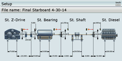
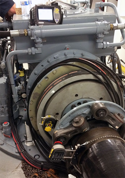
The interesting about this application is that the driveshaft goes through a bulkhead so there is no line of sight between the Z-drive and the diesel engine. In the image below you can see the bulkhead. The diesel engine is on the other side of this bulkhead. In this picture, we are setting up the receiver on a 17-foot jackshaft.
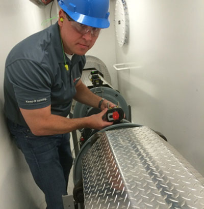
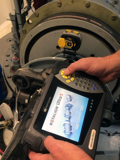
Fortunately, we had a ROTALIGN ULTRA iS Laser System (with Expert level firmware). This firmware gave us the capability to set up multiple laser heads on all of the drive train components and thereby measure the entire machine train with just one rotation. Despite the fact that two sets of lasers and receivers were on the other side of the bulkhead, we could still establish communication via the powerful Bluetooth module built into the laser equipment. The ROTALIGN ULTRA iS is the only system on the market that is capable of performing this alignment measurement across multiple couplings simultaneously with just one rotation of the driveline. In order to rotate the shafts, the drive train typically needs to be cranked by hand using a ratchet on the diesel’s flywheel. This is extremely tiring, time-consuming, and difficult to do. If you had to “crank” the diesel for each of the four couplings one at a time, the job might take several hours just to take the readings. With this alignment set-up, we were able to use the ROTALIGN’s unique Continuous Sweep measurement mode, so there was no need to stop and start at any specific measurement location.
Three sets of readings were taken to verify repeatability using the ROTALIGN’s unique measurement table. This measurement table allowed us to view each of the coupling’s three readings in a table to verify repeatability and (if desired) average these readings together. Each set of readings was accomplished with just a single turn of the shafts with less than 100 degrees rotation. The entire alignment data collection process (all three sets of readings) was accomplished in just a few minutes.
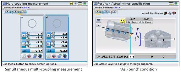
When making live moves/corrections, the ROTALIGN ULTRA iS Expert allowed us to see the alignment condition at each coupling simultaneously in real-time for both the Vertical and Horizontal directions. This is another unique capability that is extremely important, since, when one component of the drive train is moved, it affects the alignment condition at the other couplings. Having this capability is a huge time saver, reducing the job sometimes from days to just hours.
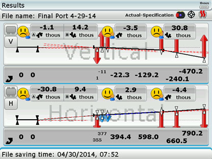
AS FOUND results:
As LEFT results:

The alignment tolerances from the coupling manufacturer were given in degrees of angularity rather than as gap differences at the coupling. To verify that the alignment was within the coupling manufacturer’s tolerances, the Rotalign Ultra allowed us to instantly convert the measured alignment condition to display the angle in degrees rather than as a gap. Below is the final reading in degrees:
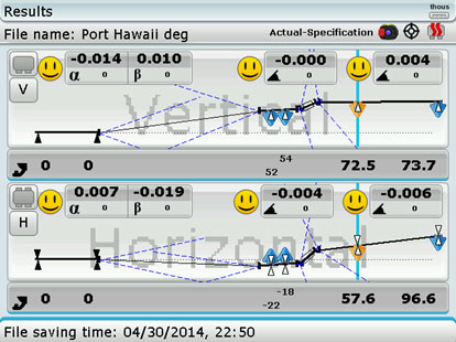
The alignment was accomplished within alignment specifications, as shown by the smiley faces. The ship’s owner was confident that alignment would not be an issue and gave the green light to put the tug into service.
by Frank Seidenthal CRL
A microchip manufacturer in the United States utilizes circular aluminum plates approximately 2 to 3 feet in diameter in the manufacturing process. These plates are heated from ambient temperature to +400 degrees F. The manufacturer wanted to ascertain if any distortion would exist across the surface of these plates when hot and if any differences in the flatness of the paste would occur between the cold and hot conditions of the plates.
To measure this accurately, a ROTALIGN® ULTRA iS with LEVALIGN® EXPERT flatness option was used. The customer fabricated a steel jig to go over the aluminum plate. The jig was insulated from the bottom (see Figure 1.)
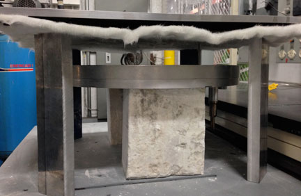
Fig. 1: Steel fixture with insulation placed over Circular Aluminum plates
9mm holes +0.002″ were pre-drilled through the steel jig to allow the Levalign plunger bracket to fit freely yet snugly through the holes and make contact with the aluminum plate underneath. A standard circular measurement pattern was selected. The ROTALIGN ULTRA iS sensor was mounted on the plunger bracket to obtain the readings (see Figure 2.)

Fig. 2: ROTALIGN ULTRA iS sensor mounted on LEVALIGN flatness plunger bracket through holes in a steel jig
All readings were repeated to within 0.0001″ and fell within 0.0001” of what the customer thought they were. A thermal expansion of 0.020″ was measured from hot to cold, although the plate remained flat to ±0.002”. Figure 3 shows the measurements being performed.
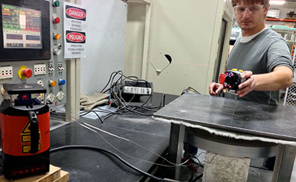
Fig. 3: LEVALIGN EXPERT on the left and ROTALIGN ULTRA iS sensor during measurements
Although the original method used to perform these measurements was not disclosed to us, the customer did tell us that the ROTALIGN ULTRA iS with LEVALIGN EXPERT saved them many hours in the measurement process, and although no dollar savings from this process were mentioned, the customer immediately purchased the ROTALIGN ULTRA iS with LEVALIGN EXPERT, without hesitation.
by Steve Lochard CRL
New portable and online-monitoring systems help extend the value of vibration monitoring into the heaviest of industrial operations. Here’s a look at how users avoided serious motor failure in mining and detected a critical bearing failure in paper-pulp production by using the right vibration products at the right moment.
Case Study #1:
A Phosphate mine is garnering big returns by monitoring numerous pieces of processing equipment with online solutions from LUDECA. The mills use several low-cost VIBNODE® online systems. The VIBNODE is a comprehensive entry-level online monitoring system that allows the end-user to access customized spectrums and time waveforms from a remote location. The system will notify the end-user via email or text message when the vibration level exceeds an alarm band.
The new monitoring system has helped the mine’s vibration group catch several problems with a newly rebuilt drive motor. The waveform showed a fuzzy amplitude modulation that increased and decreased with every RPM.
A look at the acceleration spectrum indicated a large amount of high-frequency noise well over 1g. Upon inspection, several internal retaining bolts were found to be backing out and contacting the frame of the motor rotor. The bolts were tightened to torque specifications, which was believed to have solved the problem. A week later, however, the problem reemerged as the bolts had once again backed out and began to rub. The bolts were again torqued to specification, but this time with an application of thread locker, which held the bolts in place.
Had this problem not been identified by the fuzzy waveform and a high-frequency acceleration band alarm from the VIBNODE system, the errant bolts would have quickly eaten into the motor rotor and caused a catastrophic motor failure. The motor rebuild or replacement is valued at well over $100,000. And losses to production would have been many more times this amount.
Case Study #2:
Low-speed equipment turning below 40 RPM is often difficult to analyze because of the low energy it produces. If there is not much energy, there is often not much to see. For this reason, the dynamic range of a vibration analyzer/data collector and its signal-processing quality become critical for low-speed machine analysis. Recently, a pulp mill using a VIBXPERT analyzer from Ludeca took a spectrum and time waveform on a slow-speed 35 RPM roll. The VIBXPERT is a portable, lightweight, 2-channel, FFT data collector/vibration analyzer for monitoring and diagnosis of machine conditions. As a data collector, VIBXPERT records all forms of machine vibrations, bearing conditions, process data, and visual-inspection information.
Because of the dynamic range of the VIBXPERT, the mill’s maintenance technicians were able to see a repeating pattern in the time waveform. The recurring pattern was present for every RPM and would increase slightly, then disappear for about three-quarters of the roll’s revolution. A delta cursor was placed on the repeating pattern and the source frequency was 420 CPM. This worked out to be the frequency of the inner race. A 25,000-line spectrum was also collected with a bandwidth of 7.5 CPM per line of resolution. The amplitude was very low below 0.0008 inches per second, yet a definite harmonic pattern appeared. The main harmonic pattern was at 420 CPM, with each peak having another underlying pattern of 35 CPM sidebands. The frequencies represented the inner race and roll RPM. Had this data been taken using a conventional spectrum with a resolution of 6400 lines or even 12,800 lines, this low-frequency/low-energy event would have looked like a spectrum ski slope and been ignored.
Upon removal of the bearing, a crack in the inner race was plainly visible. There was evidence the inner race had begun to walk around the shaft. If the bearing had been left in service it would have damaged the shaft and required that both the shaft and bearing be replaced. Instead, only a minimal two-hour shutdown was required to replace the bearing. Thanks to early detection, the cost of replacing a roll was averted, as well as saving the eight or more hours of lost production that a roll replacement would have required.
by Greg Lee
Recently our customer, Metropolitan Sewer District of Greater Cincinnati (MSD), shared with us their successful findings with OPTALIGN SMART. Their Maintenance Department utilizes a variety of predictive technologies and preventive strategies to support their mission of improving equipment reliability and reducing downtime.
They are committed to extending the life cycles of their assets with their already established laser alignment program.
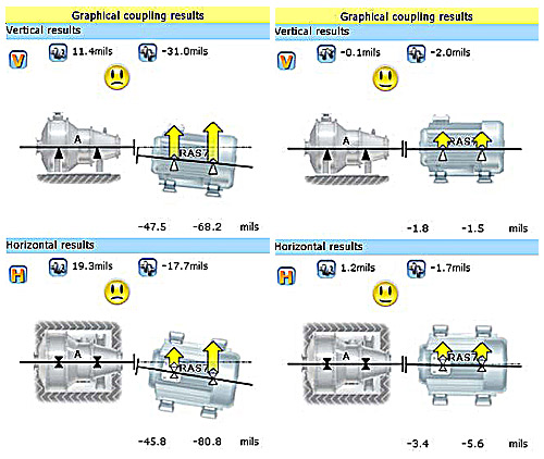
Their recent analysis started when their Maintenance Crew Leader downloaded and interpreted the alignment test results. Planned scheduled follow-up work orders, baseline testing, realignment, and retesting revealed that one of their pumps showed excessive shaft misalignment between the pump and motor in both the horizontal and vertical planes. As-found test results showed the equipment out of vertical alignment by 11.4 thousandths, and horizontal alignment off by 19.3 thousandths. The maintenance staff proceeded to generate a follow-up work order to realign the pump and motor.
Follow-up Actions:
Plant Maintenance Workers uncoupled and realigned the components, using jacking lugs and shims to correct the misalignment. After realignment work was completed, they installed a new coupling and performed follow-up retesting with the OPTALIGN SMART tool, verifying that the components had been aligned within the required specifications.
They have now proven that equipment misalignment will cause mechanical seal failure and premature bearing wear, resulting in equipment failure and unexpected downtime. By testing and aligning equipment proactively, MSD Maintenance personnel were able to identify and correct misalignment problems before irreversible damage occurred and assets would have had to be replaced. The total work order cost for testing and realigning this asset was $154.70. The purchase price of a new pump of this type is $2,456.00, resulting in a minimum cost avoidance of $2,301.30, not including labor costs to remove and reinstall the equipment.
Special thanks to our friends at Metropolitan Sewer District of Greater Cincinnati for sharing their success with us and reminding us once again that there are just No Excuses for Misalignment.
by Yolanda Lopez
I am often asked, What tools and equipment do a millwright team need to do shaft alignment? Beyond the obvious safety equipment, such as hearing protection, steel-toe shoes, work gloves, hard hat, safety glasses, and fire retardant clothing, some of the other essential equipment is not so obvious. So here’s a little list, with commentary, based on nearly 30 years of field experience:
- Laser Shaft Alignment System
- Precut Stainless Steel Shims
- Shears, Flat File, and Ball-Peen Hammer
- Pancake Jacks and Pry Bars
- Inside and Outside Micrometers
- Set of Feeler Gauges
- Torque Wrench with Crow’s Foot Adapter
- Dead Blow Hammer
- Flashlight
- Pi Tape
- White Correction Fluid and Scribe
- Cotton Rags
- Dry Spray Solvent and a Can of Compressed Air
- 50-Foot Extension Cord with Triple Tap
- Sturdy Folding Work Table and Chair
Download my entire UPTIME MAGAZINE article Equipping a Field Service Team to do Shaft Alignment
by Alan Luedeking CRL CMRP
A few weeks ago, I was doing training at an engine overhaul shop in the Midwest. They had just purchased a CENTRALIGN® ULTRA STANDARD system to perform bore alignment checks, before reassembly of each engine (see Figure 1.) After showing the mechanics how to set up the laser and take measurements on the first bore (the one furthest from the laser, as recommended), they were eager to take over and measure the bores themselves.
Before purchasing the CENTRALIGN system, they were using piano wire as their alignment tool. Now it’s a much faster and more reliable process with our laser system.
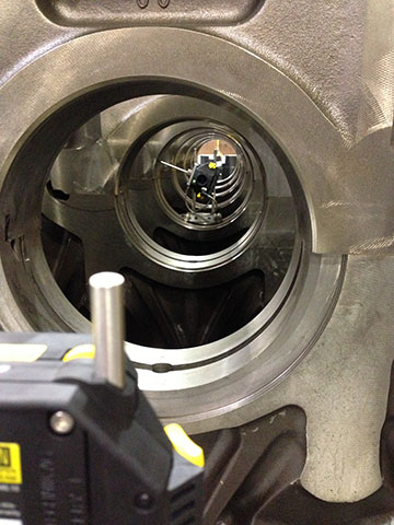
We shot the laser beam roughly through the center of all bores to create a point of reference for each bore. Next, we measured each of the bores to obtain the position of each bore with respect to the laser line. With the ability to take as many points per bore as we did, we were also able to tell if each bore was out of round. We took at least eight points along the surface of each bore, and then re-measured the entire engine to establish repeatability. The mechanics were amazed at how easy it was to measure with a laser, in comparison to the painstaking and difficult piano wire method.
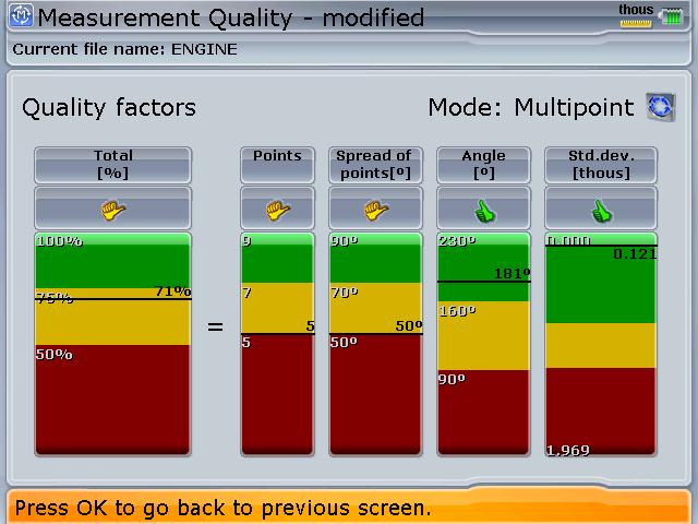
After measuring each bore, I showed them how to look at the quality factor (see Figure 2.) Seeing that they could improve their quality by taking more points, they were able to improve their measurement process. By the time they were on the last bore (the one nearest the laser emitter), the quality of their readings was near 100%. Finally, the bores at each end were fixed in the firmware to establish a reference line for the rest of the bores.
The centerline position of each bore in the engine could now be established with respect to this line (see Figure 3.)
Another interesting feature of the Centralign is that the bore alignment can be optimized to a centerline that minimizes the misalignment of the entire bore train, rather than arbitrarily establishing a reference line through any two of them. Another feature allows one to see a differential view of the alignment, which establishes the misalignment of any individual bore to a reference line formed by its two adjacent neighbors. This often saves unnecessary correction or milling work if it can be seen that the misalignment of any one bore is not too great with respect to its nearest neighbors—a very handy feature.
The mechanics were happy with the results obtained as these matched the readings they had taken with the piano wire. At the end of the training, one gentleman exclaimed, “I won’t ever use piano wire again!”
by Adam Stredel CRL
While aligning a Flowserve Booster Pump in Arkansas, the attempted alignment corrections proved unrepeatable and inconsistent. The centerline of the pump shifted from too high to too low and from too far to the right to too far left. I thought this might be a symptom of pipe stress and suggested to the customer that I check for it. Upon loosening the hold-down bolts, I noticed that piping lifted the pump right off the base.
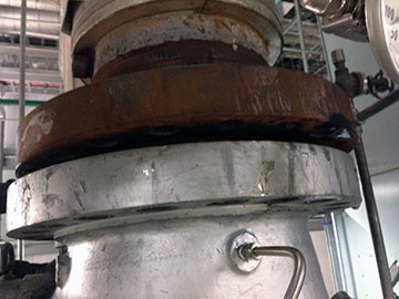
I was authorized to disconnect the piping from the pump. Figure 1 shows that at its worst one pipe was one inch out horizontally and about one and a half inches vertically, and angled to the pump.
We aligned the pump without the pipes connected. The customer was advised to redesign the pipe hangers to provide more support to the piping and reduce the stress on the pump.
It is imperative that once the pipefitting is complete and the piping is reattached to the pump, the alignment and pipe stress measurement with the laser will have to be checked once more.
by Carlos Bienes CRL
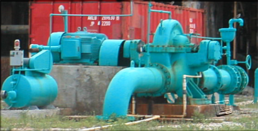
I recently visited a power plant in the Caribbean to perform vibration analysis services. As I discussed the agenda with my point of contact, I asked for a walk-through of his facility. I was a bit surprised to see the amount of rotating equipment present in such a small area. But in particular, I was surprised to hear a lot of loud noise coming from several different auxiliary machines. Even though I had my PPE gear on, I still heard a very large pitching-type noise.
As I found that noise rather high and annoying, I asked my point of contact about the particulars of this motor pump assembly. The pump has been in service for quite a while and they recently replaced the bearings and couplings.
I asked what type of method they were using to align their equipment and the answer was straight edge and dial indicator, but that the coupling and pump bearings were new.
I took the opportunity to get my VIBXPERT® II vibration analyzer out and collect data on that particular machine first. To no surprise, the data showed severe misalignment across the coupling. I reconfirmed the data using phase analysis. I noticed while doing this that the pump was hot. After viewing the data on the analyzer I asked the customer if they had thermal growth specifications for that machine. He was unaware of them having any such data for the pump. I advised him that there are systems out there that could not only perform the alignment but could also measure the amount of dynamic movement that occurs on a machine, a true cold to hot or hot to cold measurement.
The following day the customer was able to bring the machine down for a few minutes and we mounted a ROTALIGN® ULTRA IS laser alignment system and took alignment readings. Within seconds we confirmed that machines were severely misaligned, as had been indicated by the VIBXPERT. Next, we installed LiveTrend brackets and ran the machine for approximately 45 minutes, and as expected they showed a rather large positional change as they ramped up. The customer was not only able to see the misalignment using vibration technology but also found a solution to his reliability problems. The overstocking of couplings and bearings could now be reduced with the true and accurate data obtained from the laser alignment system and vibration data collector and analyzer.
by Alex Nino CRL
By Deron Jozokos with Shoreline Reliability, LUDECA solutions provider for New England and Eastern New York
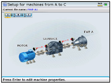
I recently helped a customer with an alignment issue they were having on a pump-gearbox-motor machine train. The problem was that although the machines were aligned within spec, after a short period of runtime the 16, 500 HP motor shaft began shuttling in and out, or “hunting” for the magnetic center, creating a fear that the coupling would break under the tremendous forces acting on it. This would in turn shut down the nuclear plant, costing millions of dollars in lost production. One theory was that the rotor was not level causing it to slide downhill while magnetic forces were drawing it back uphill. With just a short window of time, the site engineers wanted to level the motor shaft without losing the excellent alignment tolerances.
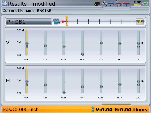
To save time, we measured both machine train couplings simultaneously using the ROTALIGN® ULTRA’s multi-coupling expert level feature. We then used the INCLINEO® system to measure the angle of the motor shaft with respect to gravity. We verified that the train alignment was still within excellent tolerances (See the ‘As-Found’ condition below) and measured a motor shaft angle of 0.489mils/inch.
Since a hydraulic torque wrench was needed to loosen the 10 total bolts, it was imperative that the number of alignment corrections be reduced to the fewest possible, preferably just one. Using the measured rotor angle of 0.489mils/inch, we calculated the correction at each foot that would level the shaft and keep the alignment within excellent tolerances. We input the calculations into the Move Simulator on the ROTALIGN ULTRA to verify our calculations then proceeded with the actual shim corrections.
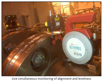
We monitored the alignment and the shaft angle in real-time with both tools and were able to get the leveling and alignment completed all in a single move (See ‘As Left’ condition below.)
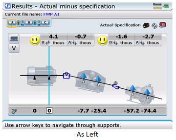
The millwrights worked as an experienced and organized team and got the shim corrections done quickly and safely. We finished the job in 1/4 the time allotted and the plant was able to ramp back up to 100% much sooner than planned. Furthermore, the plant reported that the shaft shuttling has stopped.
by Ana Maria Delgado, CRL
As Published by BIC Magazine December 2013 issue
“LUDECA’s staff is always cheerful, friendly, professional, and extremely knowledgeable. Without a doubt, LUDECA provides the greatest service and products.” — A training professional at a fertilizer company
For those companies considering laser alignment, LUDECA Inc. is offering the “why” and “who” to help you make an informed decision.
Why laser alignment? There are three main benefits of precision alignment:
- Reduced energy consumption: Significant power savings can be made through accurate alignment. Precise alignment eliminates reaction forces and reduces energy consumption by 10 percent.
- Reduced incidence of repairs: Mechanical seal repairs decline by up to 65 percent when precision alignment is carried out on a regular basis.
- Longer machine life: The smaller the offset misalignment, the greater the expected bearing life cycle.
Why LUDECA? There are three main benefits of “The LUDECA difference”:
- Industry-leading systems and services: LUDECA is a leading supplier of laser shaft alignment systems, geometric measurement systems, laser sheave alignment tools, and vibration and condition monitoring systems to the industry.
- Expert on-site and off-site training: Identifying and correcting high vibration, misalignment, and unbalance, and what causes a bearing to fail prematurely is valuable knowledge for your employees, saving you money in the long run.
- Free product and application support: LUDECA offers the highest quality system at the most affordable price — and with no additional support agreements — when compared to others.
“After attending a training course at LUDECA and witnessing the passion they have for their products and services, it was very clear to me they were leaders in their industry,” said a training professional at a fertilizer company. “I began to use their products in the 1990s with great success.
“I rely on LUDECA to provide the most accurate instruments and great technical support. I have called on them on weekends, nights, and holidays and have received the finest responses. Other companies have to think about the request and get back to you with an answer. LUDECA always has an immediate answer when a request is made.”
With LUDECA, the training professional feels like he is getting more than he pays for.
“LUDECA’s pricing is very competitive, and I know their products perform with excellent precision,” he said. “At one of our sites, a laser alignment system was purchased from another company and it stayed in the closet most of the time as it would not function, giving the mechanics headaches. With LUDECA, I know I am receiving the best.”
“Our customers are our No. 1 priority, and they understand we will take care of them,” said Frank Seidenthal, president, LUDECA. “We want to make an emotional connection with our clients. It isn’t just the product purchase. We are here for anything they need after the purchase.”
by Ana Maria Delgado, CRL