A few weeks ago, I was doing training at an engine overhaul shop in the Midwest. They had just purchased a CENTRALIGN® ULTRA STANDARD system to perform bore alignment checks, before reassembly of each engine (see Figure 1.) After showing the mechanics how to set up the laser and take measurements on the first bore (the one furthest from the laser, as recommended), they were eager to take over and measure the bores themselves.
Before purchasing the CENTRALIGN system, they were using piano wire as their alignment tool. Now it’s a much faster and more reliable process with our laser system.
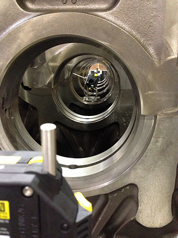
We shot the laser beam roughly through the center of all bores to create a point of reference for each bore. Next, we measured each of the bores to obtain the position of each bore with respect to the laser line. With the ability to take as many points per bore as we did, we were also able to tell if each bore was out of round. We took at least eight points along the surface of each bore, and then re-measured the entire engine to establish repeatability. The mechanics were amazed at how easy it was to measure with a laser, in comparison to the painstaking and difficult piano wire method.
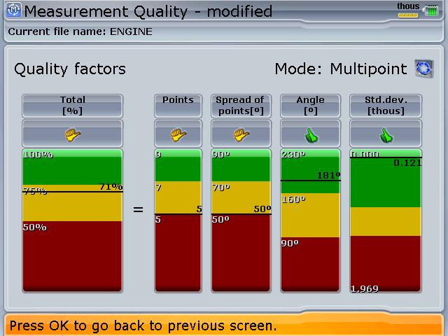
After measuring each bore, I showed them how to look at the quality factor (see Figure 2.) Seeing that they could improve their quality by taking more points, they were able to improve their measurement process. By the time they were on the last bore (the one nearest the laser emitter), the quality of their readings was near 100%. Finally, the bores at each end were fixed in the firmware to establish a reference line for the rest of the bores.
The centerline position of each bore in the engine could now be established with respect to this line (see Figure 3.)
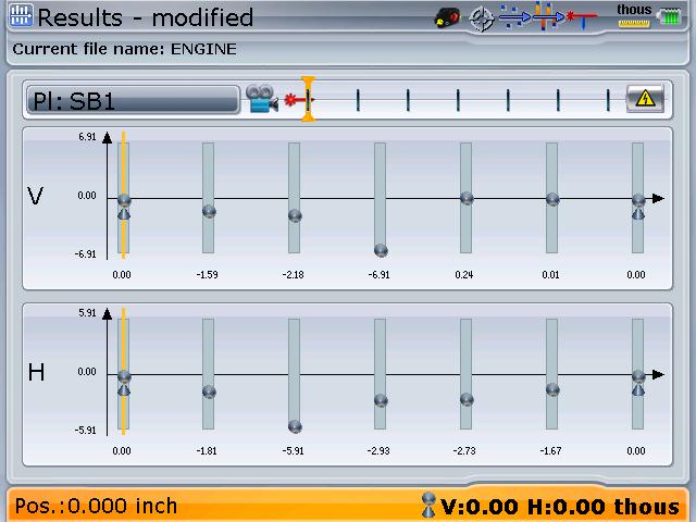
Another interesting feature of the Centralign is that the bore alignment can be optimized to a centerline that minimizes the misalignment of the entire bore train, rather than arbitrarily establishing a reference line through any two of them. Another feature allows one to see a differential view of the alignment, which establishes the misalignment of any individual bore to a reference line formed by its two adjacent neighbors. This often saves unnecessary correction or milling work if it can be seen that the misalignment of any one bore is not too great with respect to its nearest neighbors—a very handy feature.
The mechanics were happy with the results obtained as these matched the readings they had taken with the piano wire. At the end of the training, one gentleman exclaimed, “I won’t ever use piano wire again!”
Filed under:
Alignment, Articles and Case Studies by Adam Stredel CRL