Recently, while visiting the West Coast, I had an opportunity to get involved in an alignment with Mr. Roy Loop from The Rueck Company on a tug boat being built on the Columbia River near Portland, OR. This tug will be put into service halfway around the world where it will be towing and docking ships into and out of ports. A failure in this remote location would make repairs extremely expensive for the owner, not only due to its service location but because of lost revenue from the vessel being out of service.

Knowing this, the tug boat’s owner wanted to verify the alignment of the drive lines (both port & starboard) to ensure they were within the required alignment tolerances before putting the vessel into service.
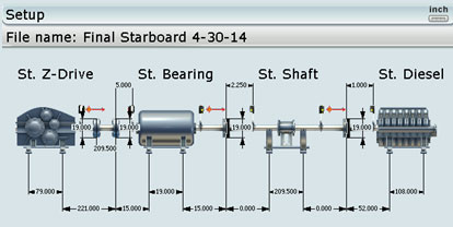
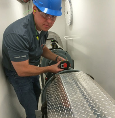
The interesting about this application is that the driveshaft goes through a bulkhead so there is no line of sight between the Z-drive and the diesel engine. In the image below you can see the bulkhead. The diesel engine is on the other side of this bulkhead. In this picture, we are setting up the receiver on a 17-foot jackshaft.
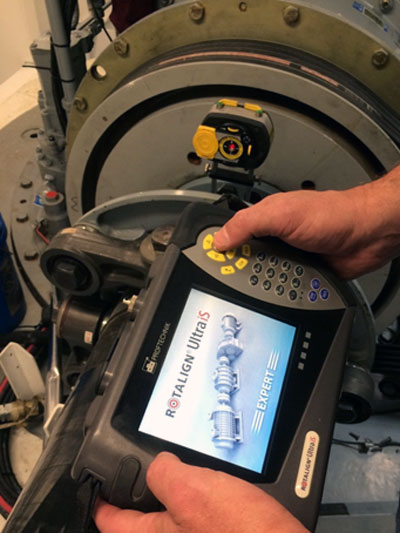
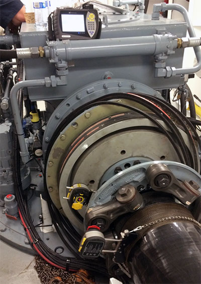
Fortunately, we had a ROTALIGN ULTRA iS Laser System (with Expert level firmware). This firmware gave us the capability to set up multiple laser heads on all of the drive train components and thereby measure the entire machine train with just one rotation. Despite the fact that two sets of lasers and receivers were on the other side of the bulkhead, we could still establish communication via the powerful Bluetooth module built into the laser equipment. The ROTALIGN ULTRA iS is the only system on the market that is capable of performing this alignment measurement across multiple couplings simultaneously with just one rotation of the driveline. In order to rotate the shafts, the drive train typically needs to be cranked by hand using a ratchet on the diesel’s flywheel. This is extremely tiring, time-consuming, and difficult to do. If you had to “crank” the diesel for each of the four couplings one at a time, the job might take several hours just to take the readings. With this alignment set-up, we were able to use the ROTALIGN’s unique Continuous Sweep measurement mode, so there was no need to stop and start at any specific measurement location.
Three sets of readings were taken to verify repeatability using the ROTALIGN’s unique measurement table. This measurement table allowed us to view each of the coupling’s three readings in a table to verify repeatability and (if desired) average these readings together. Each set of readings was accomplished with just a single turn of the shafts with less than 100 degrees rotation. The entire alignment data collection process (all three sets of readings) was accomplished in just a few minutes.
When making live moves/corrections, the ROTALIGN ULTRA iS Expert allowed us to see the alignment condition at each coupling simultaneously in real-time for both the Vertical and Horizontal directions. This is another unique capability that is extremely important, since, when one component of the drive train is moved, it affects the alignment condition at the other couplings. Having this capability is a huge time saver, reducing the job sometimes from days to just hours.
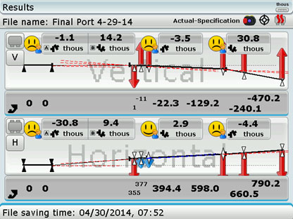
AS FOUND results:
As LEFT results:

The alignment tolerances from the coupling manufacturer were given in degrees of angularity rather than as gap differences at the coupling. To verify that the alignment was within the coupling manufacturer’s tolerances, the Rotalign Ultra allowed us to instantly convert the measured alignment condition to display the angle in degrees rather than as a gap. Below is the final reading in degrees:
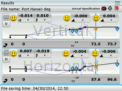
The alignment was accomplished within alignment specifications, as shown by the smiley faces. The ship’s owner was confident that alignment would not be an issue and gave the green light to put the tug into service.
Filed under:
Alignment, Articles and Case Studies by Frank Seidenthal CRL