UPTIME • December 2013/January 2014
AES Southland provides power to Southern California from a multitude of power resources. In 1998, AES Southland acquired the Alamitos natural gas power plant from Southern California Edison. Since that time, AES has undertaken a number of programs to modernize the generating station and improve the reliability of the Alamitos facility.
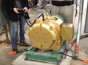
In 2010, AES Alamitos’ Units 3 & 4 boiler circulating pumps and Units 5 & 6 exciters were identified as having reliability issues. These machines were never equipped with vibration probes and only the metal temperatures of the exciter pedestal bearing and common lube oil drains were monitored by the control room recorders. Due to the low cost of implementation and OMNITREND® software compatibility, it was decided to purchase and install a VIBNODE® monitoring system to improve the reliability of the AES Alamitos Units 3 & 4 boiler circulating pumps and the Units 5 & 6 exciters.
Download the entire article RETROFIT MONITORING WITH BIG PAYOFF RESULTS by Jim Cerda and Greg Lee.
by Greg Lee
MAINTENANCE TECHNOLOGY • November 2013
Management’s decisions are major factors in the success of most efforts around a facility, including ensuring equipment health and uptime. The wrong ones can erect obstacles. How does your management team stack up?
Management is responsible for ensuring that a facility performs in line with certain safety, operational, maintenance, environmental, competitive, and financial goals. Even on a good day, this can be a daunting task.
Every cost-effective resource available should be leveraged to achieve those goals. Condition monitoring (CM) is one such resource. Management teams have, unfortunately, been known to make some mistakes when attempting to implement successful condition-monitoring programs. Understanding those mistakes is key to a site capturing the returns that it seeks from its CM efforts. Thus, it’s important to beware of the following situations:
Mistake #1: Failure to plan and execute correctly
Mistake #2: Failure to support adequate training
Mistake #3: Failure to use technology appropriately
Mistake #4: Failure to commit to full-time CM personnel
Mistake #5: Failure to create widespread awareness
Mistake #6: Failure to effectively integrate data
Mistake #7: Failure to create standards
Mistake #8: Failure to create sufficient collection schedules
Mistake #9: Failure to be proactive
Mistake #10: Failure to properly apply CM technologies
Read my entire article Condition-Monitoring: 10 Common Management Mistakes
by Trent Phillips
UPTIME • October/November 2013
“Many different tools have been used over the years to detect changes in machinery condition. The human hand, eye, and ear have been the oldest tools used to detect conditional changes in machines. It is important to understand the value and limitations of our human senses.”
Most machines give some indication that a potential component failure is about to occur that will lead to a functional failure. Our goal should be to identify, monitor, and correct components that are failing before they create a functional failure that will prevent the machine from performing as intended. Condition Monitoring is a primary tool used for this process. For example, a bearing defect is an example of a potential failure. The bearing would be monitored for degradation and replaced before it completely fails, preventing the machine from performing its intended function (functional failure.)
It could be argued that God created the first condition monitoring instrument when he created man. Our main senses are touch, sound, sight, taste, and smell. Additionally, humans have other senses that can detect balance, heat, pain, etc. All of these senses can provide very valuable data about the environment around us and the equipment we work with each day. Therefore, the human being is the first CM instrument to be used—versatile in application and proven to be very a beneficial tool.
Download my entire article Moving Beyond our Human Senses
by Trent Phillips
If you want to find the secrets of the universe, think in terms of energy, frequency and vibration.” ? Nikola Tesla
Could Tesla’s secret be the energy wasted due to vibration at a frequency equal to shaft speed all caused by rotor unbalance?
Balanced rotors are critical for achieving production and profit goals. Unbalance creates high vibration, which leads to other faults resulting in decreased machine life, wasted energy, and reduced efficiency. Smooth-running machines are required for producing products that meet customer specifications. The IOSR Journal of Mechanical and Civil Engineering states that rotor unbalance is the major cause of vibration problems. A good balancing process is essential for successful physical asset management.
Read my entire article Field Balancing Rigid Rotors at Reliable Plant.
by Bill Hillman CMRP
Simple Defect Elimination
PUMPS & SYSTEMS • July 2013
Defect elimination is a simple maintenance strategy with seemingly obvious value. However, how many facilities pursue it to the greatest degree of value? According to Webster’s online, a defect is “an imperfection that impairs worth or utility.”
The “utility” part of the definition is significant because every process industry professional focuses on uptime. If a machine has a defect, but it still works (still makes widgets) and that machine imparts defects into the widgets, the worth of that widget is reduced. Or if the machine still works, but production is slowed, the number of widgets produced over time is reduced. The worth of widgets sold is also reduced.
Defects cost money. If end users candidly investigate, they may see that they are investing money in keeping their defects. How? Money lost because the widgets are being sold at a reduced price or because the maximum number of widgets were not manufactured because of slowed production or downtime is money invested in keeping defects. Even worse, some operators are on long-term payment plans for their equipment, so they continue to invest in the same defects year after year.
The second part of the definition is elimination. According to Webster, eliminate means to put an end to or get rid of. The absence of a defect also means the absence of the investment required to sustain the defect. An asset that is free of defects is an asset that can be optimally profitable. Defect elimination usually requires an investment. Rarely does simply tightening a bolt or performing an equally trivial task fix an expensive problem.
Read my entire article Simple Defect Elimination at Pumps & Systems
by Mike Fitch CRL
Combine vibration monitoring and ultrasound for more cost-effective predictive maintenance
The best overall machinery monitoring program is one that utilizes multiple, integrated monitoring technologies.
In brief:
- The best overall machinery monitoring program is one that utilizes multiple, integrated monitoring technologies that are well-suited to detect expected failure modes.
- One goal of PdM is to determine how much time is left before a machine will fail, so plans can be made to minimize downtime and damage while still getting the most useful life from the machine.
- An application where ultrasound and vibration work well together is a mechanical inspection.
Reliability-centered maintenance programs are most effective and most profitable when a variety of appropriate technologies and tools are used to complement one another. Vibration analysis and ultrasound are as complementary as two sides of the same coin. Ultrasound is a useful monitoring tool, capable of detecting failing rolling element bearings and over-and under-lubrication conditions. The best overall machinery monitoring program is one that utilizes multiple, integrated monitoring technologies that are well-suited to detect expected failure modes. For low-risk machines, vibration analysis can be performed by a mechanic or operator using a vibration data collector or vibration meter. For machines of higher criticality, a certified vibration analyst should use advanced vibration data collection and analysis hardware and software.
Read my comments in this valuable PLANT SERVICES article.
by Trent Phillips
The ROTALIGN ULTRA laser system with Continuous Sweep allows turbine coupling checks with two measurements to be completed in as little as 6 minutes instead of 6 hours. The time savings can be further increased by using multiple laser systems for each coupling and having them start at the same time.”
ENERGY-TECH • April 2013
A power turbine consists of multiple rotors that are joined by couplings. A critical point in the service of a turbine is the coupling check. This check determines the position of the two faces of the coupling with respect to each other.
A “16-point check” has been the standard measurement method for verifying this coupling alignment. In its core form, it is like the “rim and face” check used in standard dial indicator alignment.
The rim readings are measured by a dial indicator that indicates along the edge of the coupling. This reading verifies the offset at the center of the shafts at the coupling point (providing of course that the coupling hubs themselves are not out-of-round or eccentric to the shaft centerline.)…
Continue reading my entire article at Energy-Tech.
by Daus Studenberg CRL
As Published by BIC Magazine March 2013 issue
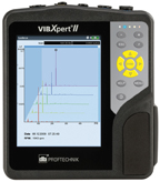 LUDECA’s VIBXPERT® II is exemplary of the company’s line of products designed to ‘Keep It Running.’ The slogan is indicative of what LUDECA’s condition monitoring solutions are committed to doing — keeping U.S. manufacturing running and productive.
The VIBXPERT II is a portable vibration analyzer with a full-color display, fast data acquisition, and powerful diagnostics tools. It combines the advantages of a rapid processor with a brilliant energy-efficient color VGA display. The diagnostic capabilities allow machinery reliability issues to be identified so corrective action can be taken to keep your equipment running and avoid unwanted downtime.
Ray Wonderly, the owner of Advanced Maintenance Technologies, purchased his first VIBXPERT from LUDECA in 2006 and upgraded to the VIBXPERT II in 2010 after being very satisfied with the company’s laser alignment systems (OPTALIGN PLUS) and customer service.
“Using the VIBXPERT II vibration system has substantially increased my business and customer base,” he explained. “It is a great selling point to my customers when I tell them I can take more vibration measurements and monitor more total equipment in less time because of the outstanding speed of the vibration analyzer itself without affecting the quality of vibration measurements.”
Wonderly found the “extras” LUDECA provides at no additional expense refreshing.
“Many vendors have it as a requirement that you purchase their additional and expensive maintenance support agreements in order to receive additional free firmware and software updates,” he explained. “LUDECA offers the highest quality system at the most affordable price — and with no additional support agreements — when compared to others.
“I have told many people if you just want a basic system at the absolute lowest price, LUDECA’s VIBXPERT may not be the best fit. But if you are looking for a top-of-the-line system at a fair price with many great features, the VIBXPERT is a great choice. You can buy it as more of a basic system and at a cheaper price and kind of grow into the many additional features as needed or required, such as the balancing or advanced diagnostics. The firmware is already built into the device and all you have to do after purchase is open it with the provided ID and password. You don’t have to send the system back for additional firmware features.
“In my personal opinion, LUDECA offers the highest quality system at the most affordable price and absolutely fantastic technical support. I truly feel you are getting more for your money as compared to some of the others.”
“At LUDECA, we maintain a high standard of ethics, service, and customer support by always striving to exceed customer expectations,” said Frank Seidenthal, president, LUDECA.
by Ana Maria Delgado, CRL
As Published by BIC Magazine December 2012/January 2013 issue
LUDECA has unveiled a new logo, slogan and mission statement backed by the same fundamental values on which the company was built.
“Our new slogan — ‘Keep It Running’ — is indicative of what our condition monitoring solutions are committed to doing, which is keeping U.S. manufacturing running and productive. It is what we have been doing all these years, and it was time to put it in writing.” — Frank Seidenthal, president, LUDECA Inc.
What began in the 1950s as a company in Nicaragua has since expanded to the United States and outgrown its smaller stature. LUDECA Inc. branched out with U.S. operations in Miami in 1979 with only three employees selling a pre-programmed dial indicator system at a time when the Internet and computers were virtually nonexistent within the maintenance arena.
“Everywhere you turn now, the access to information is tremendous,” Seidenthal said. “Along with all of this technology, our product range has also expanded extensively to include not just shaft alignment but geometric tools, portable and online vibration analysis solutions, and balancing tools.”
To accommodate the growth during the last few years, the company moved to a state-of-the-art facility in Doral, Fla., and grew employment by an additional 15 percent in 2012 alone. Additionally, LUDECA now has field offices in several locations throughout the United States. In light of the growth, the team at LUDECA has unveiled a new logo, slogan, and mission statement backed by the same fundamental values on which the company was built.
“We wanted a look and feel that was fresh and modern to reflect our growth and core company focus,” Seidenthal explained. “Not only do we sell state-of-the-art cutting-edge products but we also improve our customers’ equipment reliability. We created a mission statement to emphasize this priority to both our employees and our customers that, at LUDECA, we maintain a high standard of ethics, service, and customer support by always striving to exceed customer expectations. The proof is in our growth and high rate of repeat business.”
The company’s new mission statement reads “LUDECA’s goal is to be the premier provider of reliability solutions and technologies to industry. Our years of experience and wealth of knowledge make it possible to offer the very best service and support to our customers. We are, and seek to remain, the leading suppliers of laser shaft alignment and geometric systems, laser sheave alignment tools, and vibration and condition monitoring systems to the industry. LUDECA’s commitment to our customers strengthens our reputation as the very best in our fields, thereby creating and maintaining long-term customer partnerships.”
“We view our employees as our greatest asset,” Seidenthal said. “And in line with taking care of our customers, we take very good care of our employees and invest heavily in our staff to ensure they are always up to the challenge. They are our front-line personnel, and it is extremely important they are able to fulfill the needs and requirements of our customers.”
“In turn, our customers are our No. 1 priority, and they understand we will take care of them. We want to make an emotional connection with our clients. It isn’t just the product purchase. We are here for anything they need after the purchase.”
by Ana Maria Delgado, CRL
This is Part 2 of a 2 part series, see Part 1 here.
After the proper groundwork has been completed, it is time to build the database for your CM technology. Read my article in IMPO Magazine which includes the last 5 Steps to Successfully Implementing a Vibration Program:
#6: Database structure
#7: Interfacing with other plant systems
#8: Build a database
#9: Create standard reports
#10: Get help
by Trent Phillips
This is Part 1 of a 2-part series.
Selection of a condition monitoring (CM) technology is not an easy task and requires that many concerns be taken into consideration. Determination of what functionality is needed, selection of a technology provider that can deliver the required technology, and an available budget are all critical considerations to think about before making a purchase. Otherwise, the intended results will not be found and the new CM technology will not provide value to the reliability efforts within your facility or corporation.
Management often fails to correctly consider how to successfully implement the CM technology once the selection has been made. The failure to consider beforehand how the CM technology should be implemented within their facility or corporation leads to:
- Increased labor
- Increased expense
- Living with the unsatisfactory results for a very long time
- Unsatisfactory results from the CM technology, including:
- Missed technology findings
- Lack of integration into the existing business process
- Inability to create standards
- Inability to generate meaningful reports
Read my article in IMPO Magazine which includes the first 5 Steps to Successfully Implementing a Vibration Program:
#1: Getting Started
#2: Do you already have a technology database available?
#3: Determine what equipment will be monitored
#4: Obtain required equipment information
#5: Create equipment templates
by Trent Phillips
Tie condition monitoring into RCM and RCA.
Use the information to assess machine health.
In brief:
- Where does CM come into play in the RCM process?
- RCM draws clear and accurate boundaries around a physical asset.
- CM is not only easy to incorporate into both RCM and RCA but is essential in achieving RCM and RCA success.
A successful reliability-centered maintenance (RCM) program or root cause analysis (RCA) is difficult to imagine without condition monitoring (CM). RCM is a process that has been around for a number of years and has proven successful because of the sheer logic of the process.
Just what is RCM? We will forgo any formal definitions and answer the question by looking at how RCM works. Succinctly, RCM draws clear and accurate boundaries around a physical asset. All things contained within these boundaries are then subjected to the RCM analysis. All of the functions of that asset are then identified. In other words, what does the asset do? Then all of the ways that those functions can fail are identified and analyzed. Once this is done, tasks are developed to prevent or minimize the consequences of the failures that are likely to occur and would have a negative consequence. Simply stated, an analysis is performed and then something is done (tasks) to keep the asset functioning to a required level. It is difficult to envision a process more logical than RCM for maintaining physical assets (machinery).
Read my entire PLANT SERVICES article “Tie condition monitoring into RCM and RCA”
by Bill Hillman CMRP
WATER/WASTE PROCESSING • December 2012
Production plant analyzes resonance anomaly; looks at condition monitoring program as a profit center
Sometimes in industry, mechanical “circumstances” change. When it happens, a machine train identical to other machine trains can suddenly become atypical. This was exactly the case for Process Water Supply Pump A, whose behavior was very similar to that of its sister pump trains until something changed. In this article we discuss a problem that was abruptly encountered, the methods used to investigate it and the solution devised.
One of four identical pump trains mounted to a common piping system experienced a catastrophic motor (75 hp, 4 poles) failure. The motor could not be saved, and a new motor was purchased and installed. After installation, the pump was started with the new motor. High vibration caused the installers to immediately shut it down. The new motor had been laser aligned to the pump; therefore the alignment was not suspect; therefore vibration data was taken.
Read the entire article “Where is that vibration coming from“.
Thanks to Roger Earley with LUBRIZOL for sharing this case study with us.
by Ana Maria Delgado, CRL
The Reliability Support Team at the Eastern Processing Facility located at Cape Canaveral Air Force Station, FL, won Uptime Magazine’s Best Design for Reliability Program award.
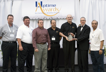
During the design phase of their program, the team was challenged with the implementation of Reliability-Centered Maintenance (RCM) principles and Precision and Predictive techniques from construction through commissioning. These have proven to be the most advantageous with regard to failure mode consequence reduction.
Congratulations to Frank Saukel, Garry Pell, and their team for this prestigious award and a job well done!
Program Highlights
1. Eastern Processing achieved Failure Mode Reduction with added redundancy.
2. They redesigned the facilities’ Reverse Osmosis Water System.
3. They performed Asset Prioritization based on safety, environmental, mission impact, and probability of failure studies.
4. They trained technicians and engineers on RCM. In the words of Garry Pell: “Don’t expect to gain tribal knowledge if you don’t invite them into the Teepee. Get your people involved from engineering to safety, from shipping to operations.”
6. They developed all maintenance procedures based on RCM decisions.
7. They identified the Predictive Maintenance (PdM) technologies and tools they needed, met with different vendors at different IMC Conferences, then focused, implemented, and trained on 1 or 2 maintenance and
Condition Monitoring (CM) technologies annually, including:
• Lubrication analysis
• Vibration analysis
• Laser shaft alignment
• Infrared thermography
• Ultraviolet thermography
• Electric signature analysis
• Ultrasound
Many discrepancies were corrected using these PdM and CM technologies. According to Frank Saukel, “Every one of the PdM technologies has paid for themselves.” For instance, they identified misalignment and motor structure resonance conditions using their VIBXPERT® vibration analyzer on several of their water pumps which had been aligned by a contractor.
Every pump was found to be bolt-bound and base-bound. They realigned all their pumps to excellent tolerance with their ROTALIGN® ULTRA laser alignment tool.

They also found and corrected electrical deficiencies with ultraviolet thermography and detected sub-grade piping leaks with ultrasound. Their precision lubrication program included oil analysis, with a resulting reduction in the number of lubricants, minimization of cross-contamination, and implementation of a color-coded system for easy machine identification and the use of accessories to control moisture. Learn more…
by Ana Maria Delgado, CRL
WATERWORLD • September 2012
The water treatment facility in the City of Fairfield, Ohio, uses vibration analysis as part of its condition-monitoring planned/predictive maintenance program to help verify and assure equipment is operating satisfactorily. The Water Treatment Plant processes an average 5.1 mgd for a population of 44,000 people with a customer base of approximately 14,000 accounts.
Public Utilities Superintendent Andreas Eddy initiated the vibration analysis program as part of a cost-savings measure with regard to the “total” operating cost of equipment associated with the water treatment process. The intent was to identify potential equipment problems at an early stage and to allow maintenance work to be performed on a proactive basis.
Vibration data was collected with the VIBXPERT® 2-channel vibration analyzer and plotted with OMNITREND® software by Prueftechnik/Ludeca. The system helped identify a “Severe Mechanical Looseness” problem on a pump installed at a pumping station considered critical to the city’s water system.
Read the entire article Vibration Analysis Helps Identify Pump Problem
Thanks to Ray W. Wonderly of Advanced Maintenance Technologies for sharing this case study with us. Special acknowledgment to Andreas Eddy, Superintendent of Water Treatment Operations for co-authoring and approving this case study.
by Ana Maria Delgado, CRL
PUMPS & SYSTEMS • August 2012
By James Laxson, Hi-Speed Industrial Services in collaboration with Mike Fitch, LUDECA, Inc.
In May 2010, an electric motor repair service provider in Little Rock, AR, began a condition monitoring program for a new customer. The customer opted for quarterly data collection.
Read the article Pump Train Component Failure, a briefcase history of a component failure in a nominal 1,800 RPM pump train.
by Ana Maria Delgado, CRL
Dial indicators can fluctuate several thousandths; no direct solution to this is available. However, with ROTALIGN® ULTRA, as with the OPTALIGN® SMART and SHAFTALIGN®, a measurement setting known as “Averaging” can be controlled (Figure 1). The averaging feature allows you to control the number of individual data points taken per reading. If there are high vibrations, or positional fluctuations being picked up by the equipment, increasing the averaging can ensure that you obtain a true measurement of the misalignment.
Further data collection analysis can be accomplished after the alignment measurements have been taken by viewing the scatter plot of all individual points/readings using the “Edit Points” feature (Figure 2). With the advanced functionality of ROTALIGN ULTRA, the points with maximum deviation can be found and analyzed (Figure 3). If, for example, one or more points were found to be random, outlying, high vibration peaks, those particular points can be disabled. By disabling the “rogue” points, the Standard Deviation (SD) of the averaged alignment measurement is decreased, thereby giving you an even more accurate representation of the misalignment (Figure 4).
by Ana Maria Delgado, CRL
Problem Overview
A customer approached LUDECA with a machine train alignment consisting of a fan coupled to a fluid drive coupled to a motor. This particular machine train had limited movement/adjustment available (See Figure 1).
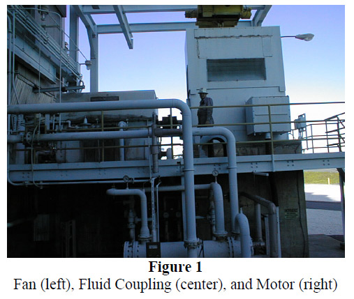
Due to the nature and geometry of the machinery, the fan on the left was stationary, and both the fluid coupling and motor were movable machines. Additionally, the fan could not be rotated. With these limitations and constraints, very careful planning was needed.
Solution
Upon arrival at the site, the LUDECA Field Service Engineer and site personnel began to analyze the situation and figure out the most efficient way to align the machine train. Using the advanced functionality of the Rotalign® ULTRA, uncoupled readings were taken across the fan and fluid coupling, and coupled readings were taken across the fluid coupling and motor. The “As Found” results can be seen in Figure 2.

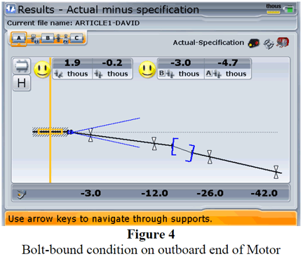
Per the request of the customer, the alignment was to meet “Short-Flex” Tolerance requirements, even though the coupling was in fact a large gear coupling whose flex planes (points of power transmission) were 13 inches apart. Upon performing the horizontal correction of the motor it became bolt-bound, which prevented further movement in the required direction, New readings were taken and the misalignment is shown below in Figure 3.

Due to the Short-Flex tolerance requirement, the motor needed to move further on both the inboard and outboard feet than was possible. To achieve the Short-Flex tolerances would require very tedious corrections, involving additional movement of both the motor and fluid coupling, or in a more extreme case, re-machining of the bolt holes in the motor feet to allow for more movement. The LUDECA Field Service Engineer suggested that Spacer Tolerances be used. With Spacer Tolerances, the large axial distance between flex planes is taken into account in such a way that the angle at each flex plane is examined individually. This can be done by examining these angles directly in mils per inch, or as the projected offsets of the machine centerlines to each flex plane across the distance between them. With the tolerances set to the spacer-type coupling, the results were viewed once again and it was discovered that the alignment was, in fact, within proper tolerances (See Figure 4). By changing the coupling type from Short-Flex to Spacer, what would have been a tedious and time-consuming task was found to be unnecessary, and was instantly resolved by entering the appropriate coupling type, in this case, spacer coupling. The spacer-type coupling takes into consideration the distance between flex planes, whereas short flex-type ignores it.
by Ana Maria Delgado, CRL
TURBOMACHINERY INTERNATIONAL • May/June 2012
Thermal growth, as used in the field of machinery alignment means machine frame expansion resulting from heat generation. The generation of heat, of course, is caused by operational processes and forces. Materials subjected to temperature changes from heat generation will expand by precise amounts defined by their material properties.
In turbomachinery, thermal growth results from the temperature differences occurring between the at-rest and running conditions. Generally speaking, the greater the temperature difference, the greater the thermal growth.
The magnitude of the growth can be calculated from three variables:
?T (temperature difference),
C (coefficient of thermal expansion), and
L (the distance between the shaft centerline and the machine supports).
When machinery begins to generate heat, the temperature difference between the at-rest and running conditions will cause thermal expansion of the machine frame, thereby bringing about the movement of the shaft centerlines.
This can produce changes in the alignment affecting the offset and/or angularity between the two machines’ shafts.
If misalignment beyond permissible tolerances occurs in the running condition, it can be observed from both high vibration and excessive power consumption. Operating machinery that is subject to thermal growth without taking into account its effects will result in a loss of efficiency, performance, and reduction in machine or component life.
Relying on the Original Equipment Manufacturers’ data sheets may not be enough as their calculations are performed on a test unit, under specified operating conditions, loads, and field conditions which may be significantly different from operating conditions in the field. These differences can drastically affect the amount of thermal growth observed on a unit in service.
Quantifying thermal growth accurately on turbomachinery to determine the amount of positional change between the machines requires expertise and/or the employment of measurement systems.
Download our article “Thermal Growth: How to Identify, Quantify and Deal with its Effects on Turbomachinery”
by Ana Maria Delgado, CRL
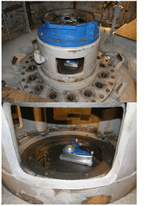 A contractor from Spokane requested a bore centerline alignment of a vertical hydro turbine in northern Idaho. After receiving more detailed information and visiting the site, it was determined that this task would be possible using a combination of the CENTRALIGN® ULTRA STANDARD (a bore laser alignment system) and the LEVALIGN® laser (a laser for flatness and squareness measurement).
Download the Vertical Turbine Bearing Alignment case study.
by Ana Maria Delgado, CRL

