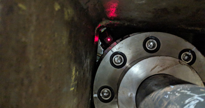
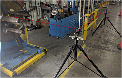
A couple of months ago, we were hired to perform an alignment on a motor/gearbox setup with a 9-foot spacer coupling in between. The obstacle this time around was that the spacer coupling was going through a steel support beam. The coupling is round but the hole in the beam was square, just big enough for the coupling to go through. With a circle going through a square, only the corners of the hole were open. This meant that line-of-sight between the two lasers was limited. Because of the obstruction there was no way to obtain data with a continuous reading. Using our dual-laser XT660 system, we decided to take readings in each available corner. We could have taken one point at each 45 degree position. However, taking more points is always beneficial. We decided to take three points (close together) in each of the corners. With two rotations, we obtained excellent repeatability. Once we had repeatable readings, we moved the machine according to the calculated alignment results and aligned it to our customer’s customized tolerances.
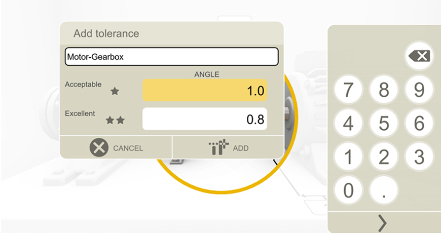

Many times we are faced with awkward alignment situations. It is helpful to have an alignment tool that is very easy to use, yet versatile to adapt to these situations. It helped that the Easy-Laser® XT660 allowed us to change measurement modes (in this case to Multipoint mode). It also helped that the tool allowed us to adjust our tolerances to the customer’s particular needs. The customer did not want to use the built-in Easy-Laser tolerances, nor the ANSI standard tolerances that are included in the system. Instead, they were looking to align the machines to within 0.1 thou/inch (or 1.0 thou/10 inches) of angular misalignment at each flex plane. So we created a custom tolerance instantaneously within the tool for this job. The customer was satisfied with the alignment and the report generated with their tolerances.
Learn more about Precision Alignment from Adam Stredel at our Rethink Maintenance Training Roadshows
by Ana Maria Delgado, CRL
December 2018 – EFFICIENT PLANT
The recently released Alignment Standard (ANSI/ASA S2.75-2017) from the American National Standards Institute, Washington (ansi.org) took nearly three years to develop. A committee of alignment experts discussed every aspect from safety procedures to the mathematics involved in defining the new standard. Alan Luedeking, CMRP, CRL, of Ludeca Inc., Miami (ludeca.com) a member of that committee, has been involved in the development of alignment standards for significantly longer than three years.
Luedeking remembers the “old days” well. Back then, personnel simply aligned components to the best of their abilities with straightedges or dial indicators. “Those alignments,” he said, “usually weren’t that good, due to sag, span limitations, obstructions to rotation, or whatever. But you did the best you could, and that was good enough because it was all you could do.”
In 1982, Ludeca introduced the world’s first computerized dial indicator alignment system (from the now-defunct Industrial Maintenance Systems Inc.), followed in 1984 by the world’s first laser-alignment system. With the improved measurement resolution and accuracy afforded by the laser sensor, a more precise definition of what constituted a good alignment became necessary. So, according to Luedeking, after poring through the sparse alignment literature that existed, Ludeca developed tolerance tables for short and spacer couplings, which, for lack of anything better, end users readily accepted. “Over time,” he noted, “these tolerance values came to be accepted as the U.S. industry standard and were adopted as the official tolerance standard by various corporate and government entities, including NASA and the U.S. Navy.”
So what are alignment tolerances, and why are they important? As Luedeking described them, “Tolerances exist because absolute perfection does not. No matter how hard you try and how long you work, you will never get a shaft alignment absolutely perfect.” He offered the following detailed discussion as to why, along with some expert advice on the meaning of the new standard and how it can help you improve your operations. Read the entire article “Alignment Tolerances Carved in Stone”


Check out the Easy-Laser XT Series, the only laser alignment platform on the market today with the new ANSI alignment tolerances built-in giving the user the freedom to choose between traditional tolerances, the new ANSI standards, or custom tolerances of the user’s own choosing.
by Ana Maria Delgado, CRL
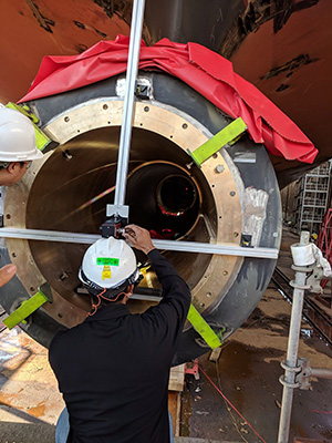

We just returned from performing a stern tube bearing carrier alignment on a large container vessel currently in construction at a leading US shipyard. The one-meter diameter bearing carriers needed to be set to specific tolerances with respect to an established datum line along the longitudinal axis of the ship. Historically, this was accomplished using optics, piano wire and depth gauges. The procedure was time consuming and considering the sizes of some of the vessels being fabricated, performing an alignment was tedious and time consuming work. Sunlight on the hull can cause considerable movement; therefore a faster alignment process would be desirable. Therefore, we were asked to bring in the Easy-Laser E950-B bore alignment system. The quick setup and operation of this wireless laser alignment system made taking bore straightness readings a breeze, saving valuable time on a warm sunny morning in dry dock. The client was pleased with the speed with which the job was performed and the ease of understanding results—a testament to the straightforward design of the E-Series software.
by Yolanda Lopez
Guest Post by Bob Dunn from I&E Central, Inc.
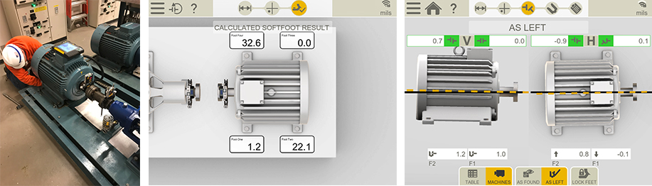

I had the opportunity to use the Easy-Laser XT440 to assist a customer in aligning a machine that had perpetually given them problems, with bearings always running hot. They had recently aligned the machine with dial indicators, but when we checked, it was off by .007, and this was on a 3600 RPM motor. We removed their old shims and did a soft foot check indicating .032 under one of the feet. Further inspection showed an angular gap under one foot. It turns out that when new, someone had ground down the feet on the motor to better align to the pump – obviously not a precision job. We step-shimmed to fill the angular gap, then aligned the machine in a single move. Several of the techniques we used were unfamiliar to these mechanics.
Takeaways:
- Do your pre-alignment homework to detect and correct foundation issues.
- Be sure mechanics are really trained in alignment – not just how to push the buttons. By the way, Ludeca Inc. and I&E Central provide excellent training.
- The Easy-Laser XT-Series is a fast, accurate, and incredibly easy-to-use tool for coupling alignment and more. If you use something else, you should see what you are missing!
by Ana Maria Delgado, CRL
As Published by Solutions Magazine March/April 2018 issue
by Ana Maria Delgado, CRL and Shon Isenhour, CMRP CAMA CCMP, Founding Partner at Eruditio LLC


During the many root cause analysis (RCA) investigations we facilitate and coach, we notice some themes that continue to manifest themselves in the findings. Often, they are grouped under the heading of precision maintenance or lack thereof. Let’s take a look at some of them and determine if they are also killing your reliability.
The six killers are grouped into three areas: Lubrication, Misalignment, and Undiagnosed Wear.
Click here to read the full article.
by Ana Maria Delgado, CRL
Guest post by John Lambert at Benchmark PDM
Recently I have been seeing the P to F interval curve popping up a lot on my LinkedIn feed and in articles that I have read. It was a concept that I was first introduced to when I was implementing Reliability Centered Maintenance into the Engineering and Maintenance department at the plant where I worked at the time. It was a great idea, that if done correctly is a maintenance benefit. Why, because it’s cost savings and cost avoidance. Let me explain this.
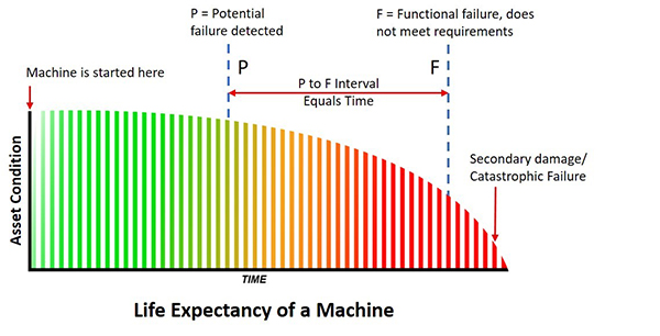
The P to F curve was used as a learning tool for Condition Based Maintenance. The curve is the life expectancy of a machine, an asset. The P is the point when a change in the condition of the machine is detected. The F is when it reaches functional failure. This means that it is not doing the job it was designed to do. For example, if it were a seal that is designed to keep fluids in and contamination out and is now leaking, it’s in a state of functional failure. Will this put the machine down? Probably not, but it depends on the importance of the seal and the application. This is an important point because the P (potential failure) is a fixed point when you detect the change in condition but the F (failure) is a moving point. Not all warnings of failure put the machine down very often you have options and time. Consider this: If I have a bucket that has a hole in it, it is in a functional failure state. But can I still use it to bail out my sinking boat? You bet I can!
Failure comes at us in many ways and obviously, we have many ways to combat it. If you detect the potential failure early enough (and it can be months and months before actual failure) it means that you can avoid the breakdown. You can schedule an outage to do a repair. It’s not a breakdown, the machine hasn’t stopped, it’s no downtime. This is cost avoidance and the plant can save on the interrupted loss of production because of downtime costs.
There are a lot of examples of cost avoidance and also of cost savings. For instance, at the plant I worked at we used ultrasound to monitor bearings. We detected a very early warning in the sound level and were able to grease the bearing and the sound level dropped. We saved the bearing of any damage, and we saved a potential breakdown so this is cost savings. Even if there is some bearing damage, the fact that we are aware of and monitor the situation lets us avoid any secondary damage.
It’s one price to replace a seal and it’s more if you have to replace a bearing in a gearbox. However, it can be very expensive to have to replace a shaft because the bearing has sized onto it and ruined it. Secondary, ancillary damage can mount up very quickly if you don’t heed the warning you are given with the P of potential failure. This warning of potential failure gives you time before any breakdown. The earlier the detection, the more time. Time to plan, and view your options. And what people tend not to do is failure analysis while the machine is still in service. A failure analysis gives you a great start on seeking out the root cause but starts right away, not when the machine is down.
Condition monitoring or as it’s often called Condition-based maintenance (CBM) does work. However, for me, there is a downside to this and I will explain why shortly. CBM is based on measurement, which is good because we all know to control a process we must measure.
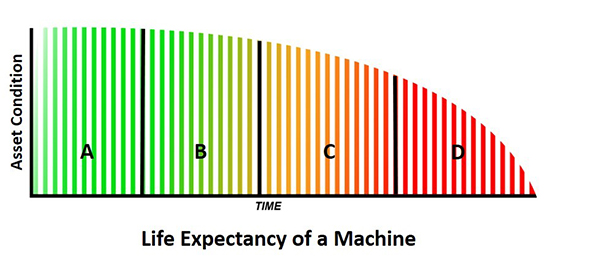
Consultants (and I’m guilty) like to put labels on things and you may see:
1. Design, Capability, Precision Maintenance
2. CBM, Predictive Maintenance
3. Preventive Maintenance
4. Run to Failure, Breakdown Maintenance
For me, the P to F interval curve starts when the machine starts. That means Design and Precision Maintenance is not in the curve and this happens before startup. A small point but it takes away from the interval meaning.
We use predictive maintenance technologies in CBM. Vibration, Ultrasonic, Infrared, Oil Analysis, NDT (i.e. pipe wall thickness), and Operational Performance. They are all very good technologies, yet it is a combination of cross-technologies that works best. As an example, vibration may give you the most information yet ultrasound may give you the earliest warning on a high-speed bearing. And then there is oil analysis which may be best for a low-speed gearbox. It all depends on the application you have which dictates what’s best for you. A lot of time and effort was placed on having the best CBM program and buying the right technology.
This, I believe, lead to the maintenance departments putting the focus on Condition-based maintenance! This I think is wrong because we still have failure. This means that CBM is no better than Predictive Maintenance. This doesn’t mean that I don’t recommend CBM, I do. To me, it’s a must-have but it does not improve the maintenance process because you still have machine failure. Machine failures fall into three categories Premature failure, Random failure, and Age-related failure. We want the latter of these. We know from studies that say that 11% of machine assets fail because of age-related issues. They grow old and wear out. This means that 89% fail because of some other fault. This is a good thing because it gives us an opportunity to do something about them.
These numbers come from a very famous study by Nowlan and Heap (Google it!) that was commissioned by the US Defense Department. It doesn’t mean these numbers are an exact reflection of every industry but the study but it has stood the test of time and I believe it has led to the development of Reliability Centered Maintenance. But let’s say it’s wrong and let us double the amount they say is age-related (full machine life expectancy). That would make it 22% and 78% would be the number of random failures. Even if we quadruple, it’s only 44% meaning random is at 56% and we are still on the wrong side of the equation. The maintenance goal has to be to get the full life expectancy for all their machine assets.
In order to get the full life expectancy for a machine unit, I think you have to be assured of two things. One is the design of the unit which includes all related parts (not just the pump but the piping as well). The other is the installation.
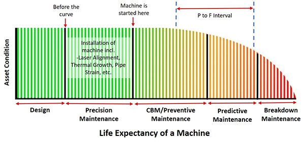
If you’re like me, and you believe that Condition Based Maintenance starts when the machine starts then you understand that there is a section of the machine’s life that happens before. You could make an argument that it starts when you buy it because, as we all know, how we store it can have an effect. However, what is important at this stage is the design and installation of the machine. In most cases, we do not design the pump, gearbox, or compressor but we do size them so that they meet the required output (hopefully). We do quite often design the piping configuration or the bases for example. All of which is very important but the reality is that maintenance departments maintain already-in-place machine assets. So, although a new installation, requiring design work is not often done, installation is. Remove and Refit is done constantly. And the installation is something that you can control. In fact, it’s the installation that has the largest influence on the machines’ life. The goal is to create a stress-free environment for the machine to run. No pipe strain, no distorted bases, no thermal expansion, no misalignment, etc.
Precision Maintenance was a term I first heard thirty years ago. It’s part of our M.A.A.D. training program (Measure, Analyse, Action, and Documentation). It’s simple, it means working to a standard. Maintenance departments can set their own standards. However, all must agree on it and adhere to it. This is the only way to control the installation process. This is the way to stop random failure and get the full life expectancy for your machine assets. The issue is that we do not have a general machinery installation standard to work to. Yes, we can use information from other specific industry sources such as the American Petroleum Institute (API) or the information from the OEM (both of these are guidelines) however nothing for the general industry as a whole. Well, this is about to change. The American National Standard Institute (ANSI) has just approved a new standard that is about to be published. I know this because I worked on it and will be writing about it shortly.
If you look at the life cycle of a machine, we need to know and manage the failure as best we can. If we only focus or mainly focus on the failure, we will not improve the reliability of the machine. We cannot control the failure. What we can control is the installation and done correctly this will improve the process giving the optimum life for the machine.
I sell laser alignment systems as well as vibration instruments. If a customer were to buy a vibration monitoring tool before they bought a laser system. I would think their focus is on the effect of the issue, not the cause. What do you think?
by Ana Maria Delgado, CRL
Guest post by Bob Dunn at I&E Central, Inc.
I was working with a customer to align sheaves using their Easy-Laser E180 sheave alignment tool. This is a new blower that had been installed by a contractor. Obviously, the contractor did not check alignment before drilling the mounting holes. The horizontal angular error was about 1.25 degrees and required a move of about 1/4″ more than was available given the placement of the bolt holes. Thanks to the digital measurement of the E180, they knew exactly what correction was needed at the feet to align this machine.
Unfortunately, the solution will be to drill out the holes in the base, then complete the sheave alignment. What should have been a 30-minute job now becomes a much larger project – time and money wasted. My guess is that the contractor checked alignment with a string (or maybe not), which did not get him close enough. Using the right sheave alignment tool makes a difference.
Thanks to Bob Dunn for sharing this case study with us!
by Yolanda Lopez
For rotating machines, it is necessary to reduce friction most of the time to increase efficiency, decrease power losses and support loads. The element of choice is the well known team of bearing and lubricant. Bearings, in their different configurations, are one of the most efficient ways to reduce friction between a stationary and a rotational part of a mechanism.

Two broad classes of bearings exist: plain bearings and rolling contact bearings. Which type of bearing is used depends on several factors related to the design of the machine and its process. Sometimes both types are used in the same machine doing different jobs. For this article, the focus is on plain bearings.
Choosing the best technology to monitor friction and condition in plain bearings is a challenge. Due to the physical characteristics of plain bearings, using vibration analysis (VA) is more effective for rolling contact bearings and less so for plain bearings. Ultrasound (US) is trending more frequently for condition monitoring of rolling contact bearings and it also shows promise for plain bearings. Understanding the physical differences between the two bearing categories is critical for developing condition monitoring strategies for plain bearings using ultrasound.
Read on to find out more about plain bearing types, failure modes and how to monitor.
by Ana Maria Delgado, CRL
May 2017 – Processing Magazine
This validated condition monitoring technology is versatile and inexpensive with a low learning curve.

Solving asset reliability issues becomes stymied when leadership is ambivalent about the benefits of adopting multiple technologies for condition monitoring (CM). When they do adopt them, they quickly learn technologies alone are not enough without the manpower to deploy them. One colleague stoically relayed his frustration when he said, “There are never enough of us (manpower), but there are more of them (problems) every day.”
Monitoring asset condition cannot be carried out effectively with only one CM technology, yet many maintenance departments rely predominantly on data from “just vibration” or “just oil analysis,” for example. More than one failure mode threatens asset health, and not every symptom is detectable by the same method. Some organizations have a strong vibration program but not anything more. Others may see clearly with infrared thermal imaging but lack a good oil analysis solution. A broader focus nets greater results.
Implementing several CM technologies is practical but often restricted by available manpower, budget, and lack of conviction from all departments. If this is your plant’s reality, perhaps start with the most versatile technology — the one that detects the most defects — with the shortest learning curve. Choose ultrasound first and build a program on that foundation.
Read my entire article to learn about the Benefits of Ultrasound, Reliability & Operational Excellence and Where is Ultrasound Useful?
by Allan Rienstra - SDT Ultrasound Solutions
Reposted from EASY-LASER® blog
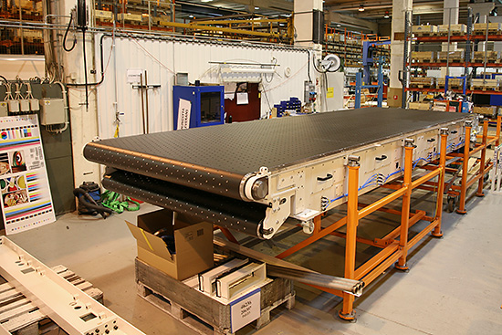
EMBA Machinery is a Swedish manufacturer of converting machines for the corrugated board industry. They acquired a measurement system from Easy-Laser® in 2015. Their machines can be found within the packaging industry all over the world. Thanks to their reliable function, short set-up time and high manufacturing speed, EMBA’s machines are renowned for high productivity and product quality.
WHAT DO EMBA’S MACHINES DO?
Stefan Stålhandske, Production technician at EMBA Machinery, answers:
To put it simply, they supply a sheet of corrugated board with flex-o-graphic printing, before creating slots, punching, gluing, and folding the sheet to produce a flat box. The final packaging has to be of the very best quality, as it is often the first thing you see when you purchase goods. The quality demands mean that the packaging also has to be strong, i.e. the corrugated board has to retain its strength through the conversion process. It must protect the packaged product during transport and handling, and it has to be stackable. It must be able to be produced quickly, and changing over the machines to a different format must also take place rapidly. Some of EMBA’s machine models produce up to 440 sheets per minute. Try to picture that!
THERE ARE STRINGENT DEMANDS REGARDING PRODUCT QUALITY, MACHINE AVAILABILITY, AND MANUFACTURING SPEED. HOW DOES THIS INFLUENCE THE IMPORTANCE OF THE MACHINES’ QUALITY?
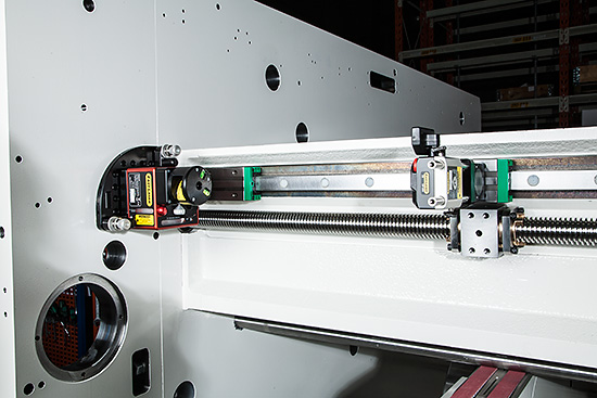
The machines are made up of many mechanical parts, both fixed and moving parts in the form of linear guides and rotating components. Many parts are dependent on one another. EMBA places stringent demands on itself and its suppliers. A separate measurement department checks machined components. Installation procedures are based on combined experience as well as generally applied requirements and tolerances. Many machine parts were previously manufactured in our own production premises in Örebro, which entailed a very high level of control of manufactured components and traceability to the machines in which they were produced. We now have a number of suppliers who have to manufacture to the same high level of accuracy, which has meant that we have been forced to develop new procedures and find new control tools.
WHY WAS THE DECISION TAKEN TO ACQUIRE LASER INSTRUMENTS?
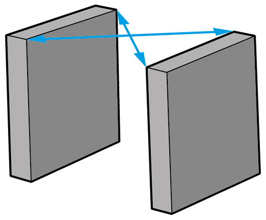
The equipment was principally procured in order to quality-assure and guarantee that all machine units are installed correctly with regard to the alignment of the stands hole center to hole center, as well as with regard to their squareness and parallelism. Previous measurement methods such as cross-measurement and measurement using specially manufactured tools must be replaced to achieve a better method of handling and documenting measurement results. We also considered that the equipment can provide us with the possibility in the future of measuring the entire machine line. Many of the machine components are large and heavy and require a mobile measurement system.
WHY DID YOU CHOOSE EASY-LASER®?
EMBA’s development department got to know the product at an earlier meeting at an industrial fair. The way we were received by Easy-Laser®, along with the versatility the instruments have to offer, made it an easy decision, I would say.

YOU MENTIONED VERSATILITY – WHAT MEASUREMENTS DO YOU CARRY OUT?
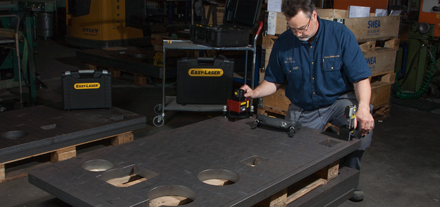
Flatness measurements on large, heavy components, as well as straightness measurements on long beams with linear guides. During installation, we align machine ends with the aid of hole centering/shaft alignment. We also measure straightness and squareness at this time, as well as parallelism between various linear movements. These measurements are performed with an E720 shaft/geo system supplemented with brackets. To measure parallelism between rolls, we have opted to supplement the system with the E975 Roll alignment kit. The instruments have also been used to perform measurements in machine tools and in order to check that diabase surface plates are level. So yes, versatility really is the right word.
HOW HAS KNOWLEDGE OF HOW TO USE THE INSTRUMENTS BEEN SECURED?
The software is user-friendly, but many of the users have never operated this type of equipment before. As a result, two training sessions have been conducted with Easy-Laser®, lasting a total of 4 days. The training has been conducted at EMBA’s premises, in machines under construction. The training, which intersperses theory with practical exercises, was divided up such that the participants began with basic geometrical measurements and hole centering in the first session. During the second session, the focus was on E975 and measurement of roll parallelism, as well as functionality checking of detectors and leveling of laser transmitters.
HOW WERE THE MEASUREMENTS PERFORMED BEFORE AND WHAT ADDED VALUE DOES EASY-LASER PROVIDE?
In some of the measurements, we have replaced devices and dial indicators. The measurements are performed more rapidly using the laser instrument, and if you are unsure of measurement data, it is easy to repeat the measurement. Above all, however, the measurements are more reliable. For example, we have linear guides installed on beams that have to move in parallel with other linear guides installed on other beams. When we measured these before using dial indicators, we were unable to capture local deviations in the same way as now.
Our laser instrument now gives us the opportunity to pinpoint these deviations as well.
In some cases, earlier measurement procedures have been replaced so that we now measure the machine from different positions instead, which are more relevant for the machine’s conditions. Some measurements have not been conducted previously. The fact that we can now perform these measurements provides us with a basis for discussions with our suppliers and contributes to our work of consistently improving our quality.
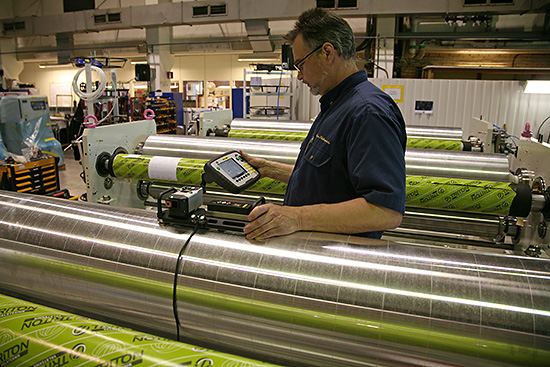
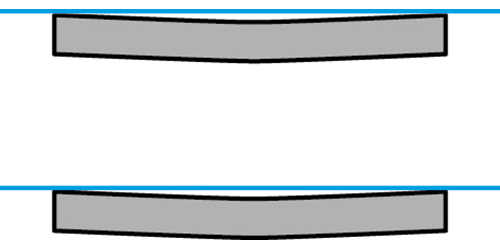
EMBA NOW USES THE ROLL ALIGNMENT KIT E975 TO MEASURE THAT THE ROLLS ARE PARALLEL WITH EACH OTHER. WHAT HAPPENS IF THEY ARE NOT PARALLEL?
Some of the most critical rolls are located in the printers. If the rolls are not correctly aligned, this can result in the print being positioned incorrectly on the package, which is unacceptable. If the feeder table is not aligned with the machine line, this results in a crooked printed image, slanting slots, slanting punching, and a folding result that is outside of the stipulated tolerances, all of which are also entirely unacceptable. As EMBA’s machines are renowned for their good range of formats as well as their high machine speed, the machine alignment from unit level to the overall machine line is an important aspect in achieving a good end result, i.e. a perfect box.
HOW WAS ROLL PARALLELISM CHECKED PREVIOUSLY AND WHAT IS THE ADVANTAGE OF E975?
When building units, we relied on the cross-measurement method as well as level with the aid of a precision level. The cross-measurement method is difficult, as access to reference points can be difficult or non-existent. When installing machines, we rely on specially manufactured spacers between the units in order to achieve parallelism as well as precision levels for leveling. Where possible, we can use tape measures to take measurements covering two separate rolls. With the laser instrument, we have the potential to measure all or parts of the machine, in order subsequently to monitor any adjustment of rolls in “live” mode.
DURING SHIPPING, YOUR MACHINES ARE SPLIT INTO SMALLER UNITS IN CONTAINERS AND ARE REASSEMBLED ON-SITE ON THE CUSTOMER’S PREMISES. THIS MUST PLACE GREAT DEMANDS ON YOUR TECHNICIANS?
Absolutely! Prior to handing over to the customer, we perform tests in accordance with a special test protocol. The tests are performed under production-like conditions, for example with measurements being taken regarding register variations in the positioning of printing, slots, and punches. The position of printing, slots, and punches must be able to be repeated within the tolerances, regardless of machine speed. In the future, new measurement methods with the aid of the newly acquired laser instrument will ensure better control of the machine set-up, which ought to generate a faster and safer start-up of production in the EMBA machine.
Thank you Stefan for giving us the opportunity to hear how you use Easy-Laser®!
by Yolanda Lopez

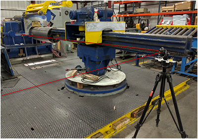
Early last year Bob Dunn with I&E Central, Inc. was approached by a customer with a unique measurement challenge. They needed to align two sheaves, 1 meter in diameter, separated by 12 meters (about 40 feet). While there are a number of sheave alignment tools available in the market, they employ line lasers, and their maximum distances are about 10 feet. Beyond that, for this application, there were physical barriers to projecting a beam right along the face or between the pulleys, so this required some application development.
They discussed with an associate and conceived a way to make this measurement using the standard detectors and programs on the Easy-Laser® E710 alignment system. The E710 is a high-end shaft alignment system with point (rather than line) lasers and 2-axis detectors with a working distance of up to 20 meters (66 feet). It also includes some basic geometric programs including straightness.
The customer’s goal was to align the sheaves in both planes, “horizontal” and “vertical”, within 0.1°. Going back to college trigonometry, 0.1° expressed as a slope is 1.745 mils/inch or 1.745 mm/meter. We can easily measure and calculate that.
The two sheaves were vertically oriented on a long superstructure with beams and supports extending about 10” out from the faces of the sheaves.
Here is how they made the measurement:
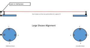
They mounted one of the laser heads (the “transmitter”) on a magnetic base with a rotating head. This magnetic base was mounted on the superstructure of the machine near the centerline of the stationary sheave, and aimed along the centerline. (See the graphic associated with this document.) The detectors themselves were extended from the magnetic bases with pairs of 12″ rods so that we had a clear measurement line along the structure.
They bucked in our transmitter between points 1 and 7 (see graphic). We did not need to set it to zero, we only needed the beam to hit the detector along the length of the measurement. Once bucked in, we used the straightness program and measured at points 1, 3, 5, and 7. Using points 1 and 3 as our reference line, the result indicated that the two sheaves were horizontally parallel within 0.05°, but were offset by about ½”.
Next, they measured the vertical alignment. Without moving the laser transmitter, they swept the rotating head and measured the slope from point 2 to 4, as 6.028 mm/meter. Then they performed the same measurement between points 6 and 8 (the far sheave), measuring 6.022 mm/meter – nearly perfect alignment (0.0003°).
The E710 proved to be a flexible and powerful tool that can do much more than coupling alignment. This new customer is already identifying additional measurements for their new system.
by Ana Maria Delgado, CRL
As Published by Maintenance Technology Magazine March 2017 issue
When it comes to electrical systems, most failures can be attributed, in large part, to installation problems, water damage, insulation issues, or poor workmanship. Such failures pose a serious safety threat and have the ability to shut down operations entirely. Ultrasound technology is a proven way to deal with them. In short, this easily deployed predictive tool offers sites a means of identifying and, thus minimizing the impact of these problems.
Read the full case study and learn how Brian Franks from JetTech Mechanical located an electrical fault with the SDT270 ultrasound system at a major water municipality.
by Yolanda Lopez
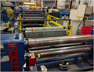
The Easy-Laser E970 laser roll alignment system is a well-established product proven to be effective in many parallel roll alignment applications such as in printing presses, steel, aluminum, and paper mills. We recently completed a roll alignment at a stainless steel roll slitting facility.
Setting the system up was fast and easy, from establishing a reference roll to creating new benchmarks. Rolls were measured for both level and skew.
Corrections were done on-site with live monitoring. The system was able to accurately measure traditionally challenging rolls with unusual surfaces, including rewinder rolls and non-magnetic rolls, such as the guide roll with a rubber surface.

The asset owner requested that the slitters and guides be checked and asked whether that was possible. The versatility of this system allowed for such an operation. By profiling the laser to a reference roll, the slitters were checked for alignment and the required adjustments were made.
The job was scoped for two days, yet the entire job with slitter alignment was completed in less than one day. This provided the time to complete a roll alignment on an entirely separate finishing operation.
The proof of good parallel roll alignment lies in the results, after running the machine: the laser aligned rolls produce consistent material thicknesses to tolerance, thereby saving tens of thousands of dollars of potentially wasted money in scrap product, not to mention if a roll had to be scrapped for this process. The E970 is an accurate performer whose versatility is straightforward by all measures™
by Daus Studenberg CRL
As Published by COMPRESSORtech2 Magazine October 2016 issue
by Karl Hoffower – Condition Monitoring and Reliability Expert for Failure Prevention Associates
Combining ultrasound and vibration sensing adds precision to recip valve analyses
Over the past decade, ultrasonic condition monitoring of reciprocal compressor valves has become more widely known. However, it does not seem to be widely used.
Ultrasonic testing measures high-frequency sound waves, well above the range of human hearing.
These ultrasound devices record the high-frequency signals for analysis later. Trending valve cap temperatures is the most common condition monitoring technique for monitoring
compressor valve health.
Ultrasonic testing of compressor valves and vibration monitoring of rotating components is an informative, preventative-maintenance practice. Compressor valve deficiencies with opening, closing, or leaking may be diagnosed using the ultrasound recording functions.
Steven Schultheis, a Shell Oil Co. engineer, addressed the issue in a paper presented at the 36th Turbomachinery Symposium in Houston in 2007.
“Trending valve temperatures have proven to be valuable in identifying individual valve problems, but are most effective if the measurement is made in a thermowell in the valve cover.” Schultheis wrote. “Ultrasound has proven to be the preferred approach to the analysis of valve condition.”
Failure Prevention Associates completed an experiment with a major midstream gas transmission company to see if this type of condition monitoring tool can effectively find fault conditions well before another technology is used.
Ultrasound meters (such as the SDT270 from SDT Ultrasound Solutions) have digital readouts that indicate the level of ultrasound detected. These devices have been used for decades to “hear” air, gas, and vacuum leaks. The intensity or amplitude of the signal is expressed in decibels — microvolts. (dB[A] μV). The dB(A) is a common intensity unit for sound intensity; μV designates the engineering reference unit being used with a piezoelectric sensor.
Converting an airborne ultrasound detector with a contact sensor allows a technician to monitor what is happening inside a machine, whether it is a bearing, steam trap, or valve.
Ultrasound detectors are designed to operate in a specific and narrow frequency band. Then through the “heterodyning” step high frequency sounds down into an audible format that the technician can hear through headphones. During the heterodyning process, the quality and characteristics of the original ultrasound signal are preserved.
Read full article complementary-condition-monitoring-boosts-reliability-article
by Yolanda Lopez
As Published by Uptime Magazine December/ January 2017 issue
Do No Harm: The Hippocratic Oath Applied to Reliability
The Greek physician Hippocrates (c.460 BC – c.370 BC) is credited with an oath that was meant to provide certain ethical standards a physician was to uphold. While maintenance is not of the magnitude as being a doctor, organizations would do well to apply portions of the Hippocratic oath to their maintenance practices. Two such examples are: “…to teach them this Art, if they shall wish to learn it, without fee or stipulation; and that by precept, lecture, and every other mode of instruction, I will impart a knowledge of the Art to my own sons, and those of my teachers, and to disciples…” and “I will follow that system of regimen which, according to my ability and judgment … and abstain from whatever is deleterious and mischievous.” This article focuses on the latter, “and abstain from whatever is deleterious and mischievous,” or in 21st century vernacular: Do no harm.”
Maintenance reliability professionals have a responsibility to their superiors to deliver results that improve the bottom line via increased uptime and productivity. But they also have a responsibility to those technicians who are expected to assist them in the process of increasing asset uptime and improving reliability. Regardless of your certification or the acronym attached to your signature block, without the technician’s solid understanding and performance of the basics, you will not achieve either goal. Two key ingredients of any reliability effort are precision installation and maintenance practices. Without them, you will find yourself replacing the same motors, pumps, etc., repeatedly.
From the reliability-centered maintenance (RCM) teachings of Stanley Nowlan and Howard F. Heap, both engineers at United Airlines, and John Moubray, the originator of RCM2, it is learned that there are six distinct failure curves. Furthermore, as many as 68 percent of failures can be attributed to infant mortality or failure induced at start-up/installation.
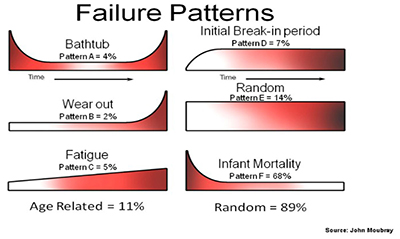
Read the full article to learn how precision installation and maintenance practices are two key ingredients of any reliability effort.
by Ana Maria Delgado, CRL
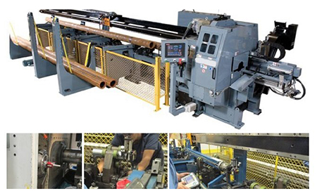
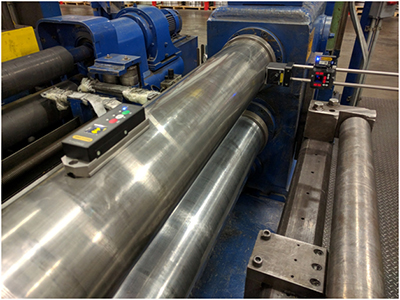
Recently, I&E Central (along with a service partner) used the Easy-Laser E940 Machine Tool system to perform alignment on an automatic lathe similar to the photo above. The lathe has an automatic feeder for 20’ sections of tube stock which are supported alternately by V-rollers and then clamped by “steady rests” while being machined. The objective of this job was to have the stock in perfect alignment with the rotational center of the spindle when supported by either V-rollers or the steady-rests. In addition, there is a pusher system that advances the stock into the collet. The movement of the pusher needed also to be aligned with the spindle centerline. This was a challenging measurement made possible by the availability of a spindle laser that could be directed back through the collet.
Measurement Procedure:
A laser transmitter was mounted in the spindle with its beam directed through the collet. The laser was adjusted to the rotational centerline, then the spindle was turned at 200 RPM for measurement. In this way, the beam precisely marked the rotational center along the entire length of the machine.
The first measurement was the location of the center of each steady rest. A laser detector was mounted on a short piece of stock, which was locked in each steady rest for measurement. A center of circle straightness program was used to measure and adjust the position of each steady rest. These were adjusted “live” so that each steady rest held the stock in line with the spindle rotation.
Once completed, pk-pk deviation in the vertical plane was 0.0095”, in the horizontal plane it was 0.020”, well within the customer’s desired specifications.
The next step was measuring the straightness of travel of the pusher arm relative to the rotational center of the lathe. This was accomplished by grasping a similar piece of stock with the jaws of the pusher, then using the same program to measure and adjust its true position at 4 locations along its travel.
The final adjustment involved adjusting the V-rolls to support the tube stock in line with the center of rotation. This adjustment was actually done without the laser. A full-length piece of stock was secured in the collet with the other end supported by the pusher. Each V-roll in turn was adjusted with shims so that it supported the stock precisely on the centerline. The customer tells us that the machine now runs smoother than it ever has.
The measurement and alignment of this machine section were never performed by the customer or any service contractor in that they had no way to make the measurements. The power and flexibility of the Easy-Laser E940 system made this a straightforward job that was completed in 1 day.
Special thanks to Bob Dunn with I&E Central, Inc. for sharing this case study with us!
by Ana Maria Delgado, CRL
Published by Uptime Magazine – August / September 2016 Issue
The foundation of any great reliability effort is the reliability culture within the organization that sustains it. Everybody within the organization must be aligned with its ultimate goals and mission for the reliability effort to succeed. Therefore, the mission and values must be clearly communicated, with reasonable expectations for compliance.
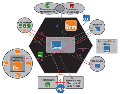
A holistic approach to reliability-centered maintenance (RCM) relies on good asset condition management (ACM). This, in turn, relies on accurate condition-based maintenance (CBM), which can only happen with good data. Planning and scheduling (Ps) personnel cannot do their job properly if the maintenance technicians do not feed good data into the system in a timely manner. So, one of the first steps must be to invest in a good enterprise asset management system (EAM) or computerized maintenance management system (CMMS), train all plant personnel in how to use it effectively and impress upon them how they as individuals are important to the overall reliability effort. Remember, the reliability effort relies as much on good data as the culture of cooperation that stands behind it and supports it. Everybody in the organization must understand the importance of their individual role in the wider mission of the organization and, in particular, their interaction with this data system.
Plant management must understand and respect the fact that the boots on the ground (i.e., their technicians and operators) are their best source of information. They are the ones that wrestle with the day-to-day problems and fix them. They know how the machines should sound, smell, and feel. Respect their expertise and opinions. Train your technicians. Invest in quality competency-based learning (Cbl). The knowledge and experience gained will pay off multifold in advancing the entire reliability effort. Give them the tools to do their job right. This means buying a good laser shaft alignment system, vibration analysis tool, and ultrasound leak and corona detection system. This CBM approach will allow your organization to optimize the preventive maintenance effort (Uptime Element Pmo) required to deal with the problem.
Read the full article to learn how you too can take your reliability efforts to the next level within your organization.
by Alan Luedeking CRL CMRP
March 2016 · Empowering Pumps Magazine
“Work smarter, not harder” is a statement we have all heard before, but who has the time to think about smarter ways to work when there is so much work to be done? Some maintenance professionals are so busy trying to keep their operation running smoothly that they often address equipment issues “reactively”. This might make maintenance teams feel more like “firemen” as they respond to in-the-moment needs. So how does a company become less “reactive” and more “proactive”?
Read the full article: Maximize Uptime with Asset Condition Management to better understand the key components of an Asset Condition Management (ACM) Program and how core technologies like Alignment, Balancing Vibration Analysis, and Ultrasound Testing can help you increase uptime.
by Dave Leach CRL CMRT CMRP
May 2016 · Plant Services Magazine
Like a lot of reliability engineers, Joe Anderson, former reliability manager at the J.M. Smucker Co., appreciated – in theory – that precise pulley alignment is critical to preventing vibration problems and ensuring successful operations.
My understanding was, ‘Yeah, we need to do it,’ ” Anderson says. “But you always have these excuses.”
When the Smucker’s plant at which Anderson worked launched a dedicated vibration monitoring and control program a year-and-a-half ago, though, Anderson quickly became a convert to making precision alignment a priority.
The plant purchased a vibration analyzer (VIBXPERT®) and laser alignment tool (the SheaveMaster® Greenline) from Ludeca to help aid in identifying machine defects that appeared to be linked to vibration caused by misalignment. Laser alignment allowed for correcting vertical angularity, horizontal angularity, and axial offset – the three types of misalignment – simultaneously. Whoever was using the laser alignment tool, then, could be sure that adjustments made to correct one alignment problem didn’t create an issue on another plane.
Read the entire article to learn how J.M. Smucker Co. made precision alignment a priority: Get your alignment in line: Don’t jiggle while you work
by Ana Maria Delgado, CRL
Reposted from RELIABILITYWEB®
- Assemble a team and identify applications for a program
- Justify needs by recognizing key areas where improvement can be benchmarked
- Set written goals for the program
- Establish how ROI will be measured
- Purchase quality ultrasonic inspection equipment
- Invest in certification training at both management and user levels
- Choose a leader to technically carry the program forward
- Establish a system to reward the successes
- Frequently review the progress as part of regular meetings
- Ensure everyone involved is 100% mentally invested in the program’s success
Tip from Hear More: A Guide to Using Ultrasound for Leak Detection and Condition Monitoring by Thomas J. Murphy and Allan R. Rienstra.
To learn more about airborne ultrasound, download a chapter preview of Hear More.
by Allan Rienstra - SDT Ultrasound Solutions