I recently conducted training at a chemical plant. During a conversation with the supervisor, he mentioned how impressed he was with how much money the ROTALIGN® ULTRA laser shaft alignment tool had saved him. They had an upcoming outage and a three-coupling machine train alignment scheduled for the back end of that outage. They were running behind schedule, as is usually the case in most facilities. He had scheduled three days for this machine train alignment, as had been scheduled in previous instances. With ROTALIGN ULTRA’s multi-coupling feature, thermal growth function, and move simulator, three millwrights were able to complete the job within six hours.
The multi-coupling feature allowed the millwrights to measure the alignment of all couplings simultaneously, with a single shaft rotation. Besides minimizing measuring time, the unit also monitored the vertical and horizontal position of each shaft as they were being adjusted. With the thermal growth function, the ROTALIGN ULTRA calculated, using real-life parameters, the effect of thermal growth at each foot along the machine train on the shaft alignment. It then provided them with proper corrections so the machine runs smoothly during operating conditions. The Move Simulator helped them find the optimal adjustments on the screen prior to actually moving the machine. These virtual moves save time by reducing unnecessary corrective moves in the field and finding the best possible solution when bolt-bound or base-bound situations occur.
Estimated savings in the cost of labor was approximately $2,700 for the three millwrights. However, if we include the cost reduction of having the equipment running two days early, increases the savings enormously. Needless to say, management was very happy and impressed with the capability of the system they just purchased.
by Adam Stredel CRL
Design, installation, and startup are the biggest contributors to a reliable or unreliable plant. It is difficult or impossible for a Maintenance Department to overcome issues inserted during one of these stages. Unfortunately, most often the focus is placed on fixing the equipment after some functional failure has occurred. The focus should be placed on preventing equipment failures in the first place.
Design and installation consideration should be given to minimizing piping strain. Piping strain is affected by temperature, flexibility, mounting arrangement, and design. Distortions in machinery from piping strain can lead to increased vibration levels, bearing failures, seal failures, coupling issues, and more.
The baseplate should be flat and level. A warped baseplate can lead to soft foot conditions and difficulty in performing proper equipment alignment and reliability issues.
Soft foot conditions distort the frame of the machine and lead to bearing, seal, and electrical issues in equipment. Additionally, soft foot conditions can make the normal alignment process much more difficult.
Correct placement and adequate adjustment mechanisms for the equipment are required for proper alignment.
The design and installation must allow for any movement required to bring the equipment into proper alignment once it has been placed into position.
Good alignment of the machines also means accounting for any anticipated positional changes in the machines that occur due to thermal growth or operational loading. Compensate for this by aligning equipment to the proper targets in the “cold” condition.
The above items are a few of the things that should be taken into consideration during the design, installation, and startup processes. Failure to do so will lead to difficulty in achieving proper equipment alignment. Improper alignment leads to functional failures in equipment and reliability problems. Don’t overlook the reliability improvements that are available to you by doing good equipment shaft alignment.
by Trent Phillips
Proper equipment alignment removes many root causes of equipment failure. Some of the benefits of proper alignment with a laser shaft alignment tool are:
- Reducing vibration levels. Lowering vibration levels in your equipment will result in increased component life for bearings, seals, couplings, and other components. For example, reducing overall vibration levels in equipment by 10% can increase bearing life by approximately 40%.
- Minimizing coupling wear and failures.
- Minimizing seal failures.
- Reducing the possibility of shaft fatigue and sudden catastrophic failure.
- Reducing power consumption in running equipment.
by Trent Phillips
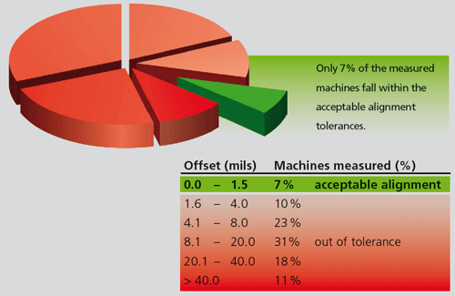
A survey conducted by one of the world’s leading rotating equipment service organizations shows that less than 10% of the 160 machines randomly chosen for measurement were found to be aligned within acceptable limits.
It is important to align your machines within specified tolerances and for that LUDECA has included Acceptable and Excellent Shaft Alignment Tolerances within their “Laser Align” mobile application. The application has an interactive Tolerance Table, where the user can input his own machine RPM and the app will kick back the respective Alignment Tolerances for both short flex and spacer type couplings. It also includes a Thermal Growth Calculator and a Soft Foot Assistant to help the user interpret soft foot values.
by Ana Maria Delgado, CRL
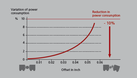
1. Reduced Energy Consumption
Significant power savings can be made through accurate alignment. Precise alignment eliminates reaction forces and reduces energy consumption by up to 10%.
2. Reduced Incidence of Repairs
Mechanical seal repairs decline by up to 65% when precision alignment is carried out on a regular basis.
The rate of repairs declines by up to 30% when precision laser alignment becomes an integral part of the pump repair schedule. Maintenance costs are also reduced through lower parts expenses and inventory levels.
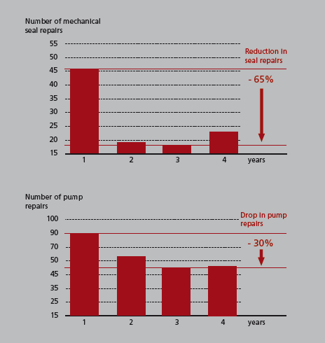
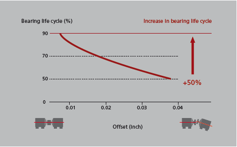
3. Longer Machine Life
Relation between offset and bearing life cycle: The smaller the offset misalignment, the greater the expected bearing life cycle.
by Ana Maria Delgado, CRL
Soft foot conditions lead to a distortion of the equipment’s frame. Soft foot can exist in several forms such as parallel air gap, bent foot, squishy foot, or an induced soft foot condition. A good laser alignment tool, adequate alignment training, and best practices will help you identify the existence and type of soft foot. This determination is critical because the proper correction method must be applied.
The resulting frame distortion can lead to several equipment reliability issues. Some examples are:
- Coupling misalignment
- Coupling strain
- Internal misalignment of bearings
- Increased radial load on bearings
- Distorted bearings
- Distorted seals
- Bent shafts
Watch our Video Course: Soft Foot Checks and Corrections
by Trent Phillips
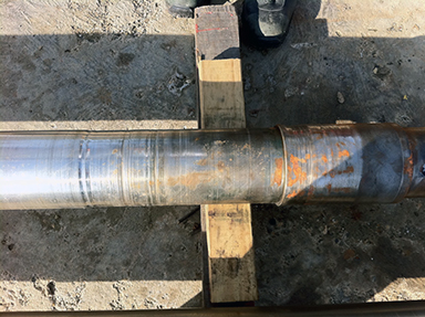
Vertical turbine pumps need frequent alignments of their guide bearings. The result of not performing the proper alignment can be seen in the image above. In some cases when maintenance disassembles a pump the damage to the shaft is so substantial, that the entire shaft needs to be replaced. This problem translates into more costly maintenance and longer downtimes. Adding bore alignment into the maintenance procedure will increase the life of the pump as well as a reducing the frequency of unscheduled maintenance.
by Carlos Bienes CRL
As Published by BIC Magazine May 2013 issue
A relatively small investment in training is a win-win scenario for the plant with a huge return
LUDECA has trained its customers’ maintenance personnel for more than 25 years. The incidence of mistreated laser alignment systems coming back for repair drops dramatically when a plant’s millwrights are properly trained in the use and care of the system. A relatively small investment in training is a win-win scenario for the plant with a huge return.
Many plants cognizant of the benefits of good training invest in a separate fully funded training department with highly qualified instructors. If you do not have this, do not hesitate to hire outside experts to come in and train your personnel, but ensure these experts really are qualified to train. Research credentials and follow-up on references.
Buy the best systems you can afford and really train your people to use them, or your equipment will be underutilized or mishandled. A well-equipped, dedicated training center provides a controlled environment where employees can learn undisturbed to their maximum potential. Equip it with good lighting, sanitary facilities, quality tables, comfortable chairs, a generous coffee pot, the latest SMARTboard™ technology, projectors, computers, and Internet access.
If you cannot provide a good training environment in-house, send employees away for training. Vendors who offer such services should have better facilities for this than you do. Ensure they do! We went out of our way to build and equip our own state-of-the-art training center and staff it with highly qualified people.
If you cannot afford to send away several employees at a time, send your most qualified employee or resident instructor for more in-depth training to have the knowledge brought back. We offer intensive “train the trainer” courses and in-depth courses for day-to-day users of our alignment and vibration systems. For us, it is a win-win proposition — well-trained users of our systems learn to love them, use them correctly and care for them properly. We offer an educational discount for systems purchased by training programs or educational institutions.
Six students per class is ideal (eight max) to allow the instructor to devote individual attention to each student, answer all questions and ensure each student gets hands-on practice. Each pair of students is assigned their own training simulator and complete laser shaft alignment system or vibration data collector and computer and necessary peripherals. Each student gets a complete set of training materials and an operator’s handbook for the system being learned to keep.
Vibration training is regarded as complex, and it can be at the more advanced levels. Yet a solid understanding of the basics of machine vibration and its underlying causes will benefit you greatly. Maintenance employees will be more attuned to spotting potential problems than they otherwise might and become more valuable, proactive members of your overall reliability program. Understanding what causes imbalance and its consequences, and what causes a bearing to fail prematurely is valuable knowledge for your employees, saving you money in the long run.
by Alan Luedeking CRL CMRP
UPTIME • April/May 2013
 There is much more to proper shimming of machines for alignment than meets the eye. There are a number of things you should consider and look out for when selecting and using shims.
First and foremost, you should be using high-quality, precut slotted stainless steel shims. Cutting your own shims by hand out of cheaper rolls of carbon steel or brass shim stock may save you money in materials, but will prove far more expensive overall for several reasons. For one thing, you will be able to cut only the thinner thicknesses with scissors or shears, whereas thicker thicknesses (over 0.004″) will require using an acetylene torch or a saw, which is labor-intensive and presents several safety concerns. After you have cut your shims by hand, it is essential to deburr them carefully with a ball-peen hammer and file. All of this will cost you the most valuable commodity of all: time. Moreover, the end result will be fewer available shim thicknesses than you would otherwise have with precut stainless steel shims, resulting in less precise alignments. In addition, if you are cutting shims by hand, there is a far higher risk of minor cuts, requiring a visit to the nurse for a bandage, with the attendant’s loss of time and safety-reporting paperwork this would entail.
It is important to select your brand of precut stainless steel shims carefully, as they vary widely in quality and tolerances. It is extremely important that the shim be of consistent quality, completely even in its thickness throughout, accurate in its thickness, flat and burr-free. Also, it should have no hazardous sharp edges. The metallurgy of the shim is also important to guarantee its hardness and corrosion resistance. Only the best quality precut stainless steel shims offer all these features. An excellent shim will always save you time and money in the long run.
Read my entire article Best Practices: Machinery Alignment Shimming and learn why:
by Alan Luedeking CRL CMRP
The alignment of machine trains can be a lengthy task. In the past, alignment data of the entire machine train had to be manually graphed to scale in order to determine the optimal moves. The ROTALIGN® ULTRA laser alignment tool can now instantly graph the alignment results of an entire machine train of up to fourteen machines to scale—maximizing efficiency and minimizing frustration. You can optimize an alignment centerline through a machine train to minimize corrective moves everywhere. Forget graph paper!” —Pedro Casanova, Manager of the Alignment Division – LUDECA, Inc.
 The Machine Train Alignment Crash Course Video provides background knowledge along with tips and procedures for efficiently completing the alignment of multiple-element drives using laser alignment equipment.
by Ana Maria Delgado, CRL
Soft foot is every alignment technician’s worst nightmare and while correcting soft foot may not be easy, it is worth every minute you spend on it, because once done, the alignment of the machines becomes a much easier task. If you want to make aligning your machinery easier, quicker and more accurate, start by correcting soft foot.” —Alan Luedeking, Manager Tech Support – LUDECA. Inc.
 The Soft Foot Checks and Corrections Crash Course Video provides insights and instructions on solving various types of soft foot, and demonstrates industry-leading techniques using laser alignment equipment.
by Ana Maria Delgado, CRL
The ROTALIGN ULTRA laser system with Continuous Sweep allows turbine coupling checks with two measurements to be completed in as little as 6 minutes instead of 6 hours. The time savings can be further increased by using multiple laser systems for each coupling and having them start at the same time.”
ENERGY-TECH • April 2013
A power turbine consists of multiple rotors that are joined by couplings. A critical point in the service of a turbine is the coupling check. This check determines the position of the two faces of the coupling with respect to each other.
A “16-point check” has been the standard measurement method for verifying this coupling alignment. In its core form, it is like the “rim and face” check used in standard dial indicator alignment.
The rim readings are measured by a dial indicator that indicates along the edge of the coupling. This reading verifies the offset at the center of the shafts at the coupling point (providing of course that the coupling hubs themselves are not out-of-round or eccentric to the shaft centerline.)…
Continue reading my entire article at Energy-Tech.
by Daus Studenberg CRL
I used the OPTALIGN® non-visible laser shaft alignment tool before the visible came out. The OPTALIGN visible before the ROTALIGN® came out and the ROTALIGN since it was first introduced. Then a ROTALIGN PRO upgrade when it became available. A lot of the alignment work I do is over great distances. On some occasions I have even used the ROTALIGN ULTRA. All PRUFTECHNIK lasers have unmatched repeatability and accuracy. I have had my work checked with other manufacturers’ lasers and by other methods. The other lasers cannot repeat over longer spans. Experience has taught me to tell them to call me when they can repeat to .020″. In the event they still think I’m out, I will return and show them the errors of their ways or their equipment. Several times a year I’m asked to do old-school verification and honestly, old-school techniques, performed in a competent manner tell the same story as the laser; but what a bunch of work!
On at least two occasions, I have had a strain gauge company from Canada check my work. The first time, a technician did not think his strain gauge equipment was calibrated due to the fact he could not get a reading that was more than 5% of what he expected to be a good answer. When his office told them it had been calibrated before he left, he did not believe it. I told them the line shaft was perfectly straight. Apparently a laser has much higher resolution than a strain gauge. DO YOU THINK! A strain gauge, oh please, maybe we should call these lasers a “no strain” gauge. After all, the purpose of precision alignment is to eliminate strain. The second time, they said they had never seen work so close.
The training we received in Miami from Pedro Casanova and others, with the instruments you provide, has allowed me to do perfect work for over 20 years.” —John Boland, Boland Industrial

by Ana Maria Delgado, CRL
Shoreline Reliability, the northeast LUDECA Solutions Provider, was a proud supporter at the 44th Annual New York Citywide Graduating Apprentice Contest. In the contest the graduating Millwrights were asked to layout, assemble and align a bevel gear project along with blueprint reading and perform laser shaft alignment demonstrations using the ROTALIGN® ULTRA iS. All tasks were directly related to what the graduating apprentices will encounter in the field. The contest was held at the New York City District Council of Carpenters Labor Technical College, where the millwright courses have utilized the OPTALIGN® and ROTALIGN products dating back to the mid-1980s. The forward-thinking school also plans to incorporate the CENTRALIGN® ULTRA for bore alignment as well as introduce vibration analysis and balancing with the VIBXPERT® II.

The contestants had 7 hours to complete all tasks and were judged on accuracy and precision. This year’s Millwright winner was Michael Giorgi, followed runner-up Michael Daniels and 3rd place went to Mohammed Arif. Congratulations to all participants and we look forward to many more years of working together with the NYC District Council of Carpenters Labor Technical College.
by Ana Maria Delgado, CRL
A lot of maintenance employees believe that small machine trains can be precision aligned more quickly and easily than larger machine trains. This is not always the case! Smaller machine trains are usually less rigid. This can cause the alignment to shift as the anchor bolts are tightened. Almost all small machine trains have some form of soft foot condition that must be corrected because the machine bases are often not flat or of inferior construction. Additionally, thermal growth can have a large impact on smaller machine trains as well.
Don’t be fooled by the size of the equipment you must precision align. It is critical to understand how the size, design, operation, and other factors affect the equipment you must align.
by Trent Phillips
In the previous article, we covered the advantages of continuous monitoring over the “snapshot” method for thermal growth measurement. We also highlighted the superiority of these methods over the existing simple thermal growth calculations and static “hot alignment checks.”
Continuous monitoring is a feature with the ROTALIGN® ULTRA LIVE TREND and the PERMALIGN® system. The most common question we receive with regards to these systems is “If LIVE TREND and PERMALIGN both offer continuous monitoring, why should I pay more for the PERMALIGN system?” The answer to that is that you have to pick the right system for the requirements of the job, and not just look at the price. The following are some factors to consider when choosing between LIVE TREND and PERMALIGN:
Monitoring Time
ROTALIGN ULTRA LIVE TREND was designed to provide short-term continuous monitoring. You could risk running out of power from the 9-volt laser battery for situations where the measurement lasts for more than 50 hours. Continuous computer operating time on battery power alone will be less (24-36 hours). This is still a generous amount of time to monitor and would suit most users.
PERMALIGN was designed to provide long-term continuous monitoring. The laser transducers are nitrogen sealed and purposely designed to maintain long-term stability for longer periods of time. In fact, the longest-running PERMALIGN job was 2 years and the data returned to within 1 thousandth of an inch of the starting position!
In thermal growth measurement, it is always better to have more than less. There have been many jobs where 1-day monitoring turned into a 1-month monitoring job. For those situations, you would be glad to have the long-term monitoring capability of PERMALIGN.
Temperature and Environment
ROTALIGN’s industry-leading 5-axis sensor (used with LIVE TREND) is designed to operate continuously within a range of 32°F – 113°F (ambient temperature). It features an IP65 rating against dust and water ingress protection.
PERMALIGN, features two laser transducers that operate within a range of 32°F – 158°F. PERMALIGN also features PCD sensors that operate in the infrared frequency spectrum. The result is a superior signal-to-noise ratio for harsh industrial (dusty and steamy) conditions. Because of this, PERMALIGN has our highest recommendation for boiler feedwater pumps (our #1 application for thermal growth monitoring), and steam and gas turbines.

Measurement Capability
Live Trend and PERMALIGN both work by measuring the inboard bearing housing movement to calculate shaft misalignment from positional changes occurring between the stopped and fully loaded final running condition of the machines. This method reliably gives information on the relative movement between two machines. PERMALIGN can be expanded to provide up to 16 channels of continuous monitoring capability. With a requirement of 2 sensors per coupling, this means that 8 couplings can be simultaneously monitored. This is an ideal solution for monitoring the movement of a boiler feedwater pump machine train.
PERMALIGN can also be expanded to provide absolute positional change monitoring capability. For this application, the sensors are mounted on sturdy pedestals attached to the foundation. The pedestals are often lined with insulation and have a continuous stream of groundwater pumped through them to ensure pedestal temperature stability. This permits monitoring of machine movement with respect to the foundation.

At this point, let us point out that we are comparing two very good systems that provide superior thermal growth measurement capabilities over other more primitive methods. The ROTALIGN ULTRA is in a class by itself for shaft alignment. The addition of LIVE TREND takes it beyond that level by providing continuous monitoring.
Since 1989, PERMALIGN has been in a class by itself for laser-based thermal growth monitoring. There is no laser system that can compare to the performance of PERMALIGN for thermal growth monitoring. Whether you choose LIVE TREND or PERMALIGN, remember that it is the requirements of the job that you must consider first. Once you have chosen the best system for your application, you can obtain true thermal growth compensation to increase the performance and lifespan of your rotating machinery.
by Daus Studenberg CRL
In the previous article, we discussed two methods for thermal growth monitoring, the “snapshot method” and “continuous monitoring”. With the “snapshot” method, we only knew the initial and final thermal growth readings, with no information in between. Some typical “snapshot” results are shown below:
Vertical Offset: -24.4 mils
Vertical Angularity: 15.2 mils/10″
Horizontal Offset: -12.3 mils
Horizontal Angularity: 7.5 mils
“Continuous monitoring” is exactly what it says: the thermal growth is “continuously monitored”. Our ROTALIGN® ULTRA LIVE TREND and PERMALIGN® thermal growth monitoring systems work in this way.
Alignment readings between the machines are taken at preset intervals for a predetermined amount of time. The relative alignment changes are then clearly displayed as a set of graphs. Here are the same “snapshot” readings, but this time displayed as a continuously monitored measurement from the ROTALIGN ULTRA LIVE TREND.

Notice the chart displays the same final “snapshot” alignment readings, but this time we see the graphs of all the positional changes that occurred along the way, from the starting to the ending position, which are not readily apparent with the simple “snapshot” method. These graphs reveal the following:
- The vertical offset had moved in the positive direction and then changed to the opposite direction.
- The readings stabilized in the last 40% of the measurement. This shows us that the final readings were taken when the machine had stabilized.
- There are no sharp drops or radical moves. We are assured the bracket was not bumped or hit during measurement.
- The readings were consistent, indicating that vibration was not severely influencing the results (which can be compensated for by simply increasing the number of points taken per measurement at each interval).
It is essential to get dependable and reliable results for thermal growth studies because you will be deliberately misaligning a machine for the purpose of improving the alignment. Individual events during the monitoring period can be tagged and commented upon, thereby allowing the effects of external actions (such as opening or closing a valve, changing the load on the machines, or starting a nearby machine, say) to be documented. The extra information gathered by continuous monitoring is very useful for thermal growth monitoring. Continuous monitoring provides essential evidence for the user to confidently state, “it is what it is”, with regards to misalignment due to thermal growth.
In Part 3 of this article, we will discuss how to choose a thermal growth monitoring system.
by Daus Studenberg CRL
“Thermal growth” often refers to the change in machinery positions as a machine runs from startup to operating conditions (or vice versa). Machinery positional change can also be caused by dynamic forces, pipe stress, and other factors. Compensating for thermal growth is necessary because the machine will be misaligned during operating conditions if it is not.
We offer two methods for the measurement of thermal growth. One is a “snapshot” method and the other is continuous monitoring. Our current line of M3 brackets provides an accurate and easy-to-use method to take a measurement using the “snapshot” method.

A reading is taken by mounting the sensors and rotating both brackets to create a “virtual” shaft alignment reading across the coupling. Measurement is taken before and after the machine is running. The difference between the two measurements is the change in the alignment.
M3 brackets provide a cost-effective method of measuring thermal growth because they can be used with any of our current shaft alignment product lines. It should not be confused with the static “hot and cold alignment check” (where shaft alignment equipment is mounted on the shaft and readings are taken conventionally, before and after startup, on a machine that is not running). Assuming that the bracket was never bumped or moved during the measurement, the results are much more accurate than those obtained by the static “hot and cold alignment check”. Below are typical results one could expect to see from startup to running conditions:
Vertical Offset: -24.4 mil
Vertical Angularity: 15.2 mil/10”
Horizontal Offset: -12.3 mil
Horizontal Angularity: 7.5 mil
You will probably notice that a significant amount of angularity exists, which goes against a lot of assumptions in thermal growth calculation methods where it is assumed that the machine will grow an even amount. When taking thermal growth readings using the “snapshot” method, you will want to confirm (establish repeatability) the measurement. This can be accomplished by taking another reading on cool down. The difference in the cold-to-hot and the hot-to-cold readings should be very similar, but with the opposite sign. This is an essential practice because you are making the assumption that the bracket was never accidentally moved or bumped. In Part 2 of this article, we will show how “continuous monitoring” can provide a more complete and accurate picture of what is going on with thermal growth.
by Daus Studenberg CRL
WATER/WASTE PROCESSING • December 2012
Production plant analyzes resonance anomaly; looks at condition monitoring program as a profit center
Sometimes in industry, mechanical “circumstances” change. When it happens, a machine train identical to other machine trains can suddenly become atypical. This was exactly the case for Process Water Supply Pump A, whose behavior was very similar to that of its sister pump trains until something changed. In this article we discuss a problem that was abruptly encountered, the methods used to investigate it and the solution devised.
One of four identical pump trains mounted to a common piping system experienced a catastrophic motor (75 hp, 4 poles) failure. The motor could not be saved, and a new motor was purchased and installed. After installation, the pump was started with the new motor. High vibration caused the installers to immediately shut it down. The new motor had been laser aligned to the pump; therefore the alignment was not suspect; therefore vibration data was taken.
Read the entire article “Where is that vibration coming from“.
Thanks to Roger Earley with LUBRIZOL for sharing this case study with us.
by Ana Maria Delgado, CRL
Right angle drives or 90-degree gearboxes are very common in the industry. These are speed reducer/increaser machines with an output shaft exiting at a 90-degree angle with respect to the input shaft. In some cases, the 90-degree turn stays on the horizontal plane. This is great because the alignment can be treated as a machine train alignment.
However, when a gearbox has an output shaft emerging vertically, the alignment becomes much more complex. This coupling should be treated as a vertical alignment, where the support of the machine is a flange, whose feet are visualized as being the flange bolt pattern where shimming takes place to correct angular misalignment. This fictitious flange is to be placed at the plane of the feet, where the shims are to be inserted or removed. Having a system that will allow you to customize the bolt pattern and bolt positions is critical in this case. Depending on the existing conditions at the gearbox feet, you may wish to choose a positive, negative, or optimized (+/–) shimming solution in order to minimize the axial effect of any shimming corrections. Offset corrections are performed by moving the machine laterally only after angularity has been corrected.
What if the shaft is not in the center of the machine but offset to one side? With the proper laser alignment system, the user can set up the alignment job so that the true shaft geometry within the machine frame is correctly represented. Only in this way can we obtain the proper corrections at the machine’s feet.

by Adam Stredel CRL