Surprisingly, often on larger machines like gas turbines and diesel engines coupled to generators or compressors, there is less space to mount your brackets than on small machines. The large size of couplings and shafts frequently means that there is very radial clearance in the OD of the coupling hub to provide line of sight, or piping or other structures interfere with rotation, limiting your axial clearances on the shafts as well.
Also, shrouds or other obstacles limiting access to the shafts can cause difficulties in turning them. Yet, there is almost always a way to do an alignment with Pruftechnik tools. Our brackets do not need to be mounted on the shaft, provided the coupling hub is solid to the shaft (ie. rigidly mounted to the shaft.) A variety of magnetic brackets and offset adapters lets you overcome almost any obstacle to rotation or to the line of sight. In fact, anywhere that you can devise a way to mount a dial indicator, you can also mount a bracket to hold a laser component. Here are a few examples:
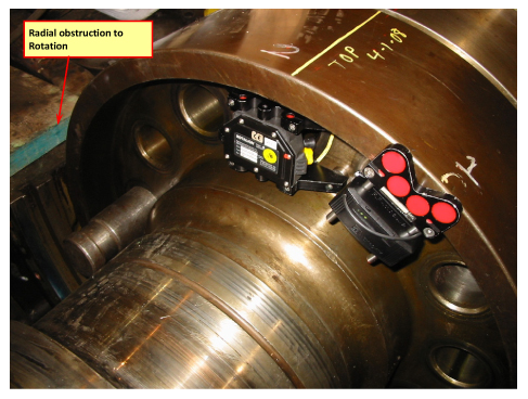
Here we see the ROTALIGN® SMART EX laser component and Bluetooth module mounted on a solid hub, shooting the beam through the coupling bolt hole. The laser emitter is mounted on the magnetic coupling bolt hole bracket designed for applications like this, and the Bluetooth module is mounted on a compact magnetic bracket, illustrating that the two components need not always necessarily be mounted on the same bracket. This setup allows the laser beam to be shot through an unoccupied bolt hole of the coupling without any hardware protrusion beyond the OD of the coupling.
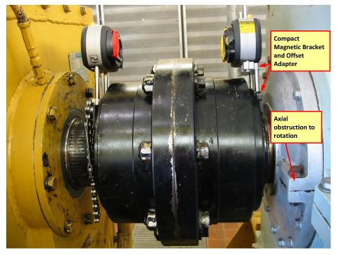
Here we see the ROTALIGN ULTRA IS sensALIGN laser (on the right) mounted with a compact magnetic bracket to the axially protruding face of the solid hub of the double-engagement gear coupling, in a very limited axial space that would not permit a standard chain bracket to be mounted on the shaft. An offset adapter moves the laser unit forward axially, permitting the setup to overcome the axial obstruction of the machine housing at 3 o’clock.
 Here we see the ROTALIGN ULTRA laser (on the right) mounted on a magnetic bolt hole bracket to the flywheel of a methane gas engine, overcoming the axial space limitations posed by the shim disk-pack type coupling.
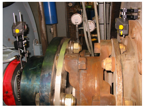
Here we see the ROTALIGN ULTRA receiver mounted on offset support posts on a compact magnetic bracket, overcoming both an axial space limitation preventing the use of the chain brackets and a radial obstruction posed by the pipe seen in the foreground on the left.

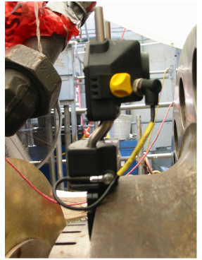
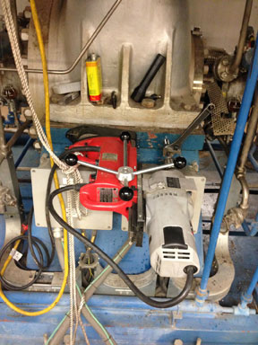
Here we see the ROTALIGN SMART EX receiver mounted on a compact magnetic sliding bracket, overcoming both an axial space limitation and a situation in which the shaft cannot be turned by hand. Instead, the magnetic sliding bracket is slid around the solid coupling hub to each measurement position while the laser is rotated past the receiver as the other shaft is rotated using the Pass Mode measurement mode for uncoupled shafts.
by Alan Luedeking CRL CMRP
Machine components are susceptible to premature wear and corrosion due in part to the harsh environments they are placed in. To combat this, here are a few suggestions to keep your machines running:
- Proper lubrication
Always make sure the movable components in the machine are getting the lubrication they need. Lubrication not only keeps parts cooler and moving freely but also prevents corrosion. - Cleanliness
Keep the machine components as well as their environments as clean as practical. This can aid in preventing wear stemming from particle ingression and friction. - Keep logs
Keep a log of all the PM (preventative maintenance) done on your machines so as to avoid duplication and prolong the life of its components.
If you follow these simple guidelines, it will help prevent breakdowns in your plant and save money.
by Oliver Gibbs CRL
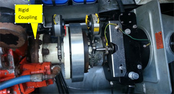
We recently visited a water treatment plant in Boca Raton, FL, and needed to align an interesting five-machine train. The train consisted of a 1000 HP motor short-coupled to a clutch, water pump, another clutch, and diesel engine (see Figure 1):
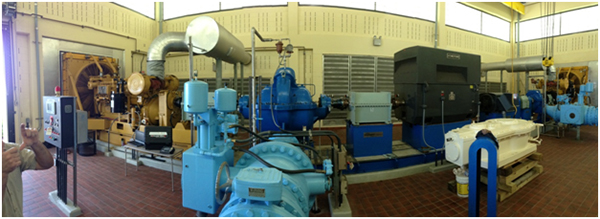
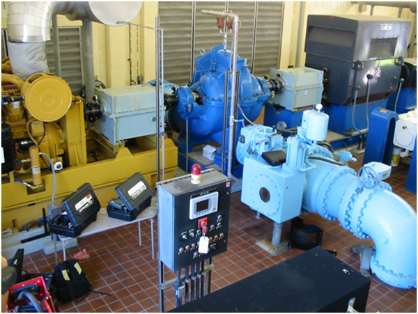
The main drive unit is the dark gray motor on the right, which spins clockwise and drives the blue pump in the middle through a clutch (the light gray machine.) The second clutch in the train is to the left of the pump (hidden in the picture above) and is oriented backward from the first one so as to disengage the yellow diesel engine at the far left of the train when the motor is running. When electric power fails and the motor cannot be used (such as during hurricanes or when an accident disables the electrical grid), the engine is automatically started and spins counterclockwise, driving the pump in the same direction as before through the left-hand clutch, whereas the right-hand clutch now disengages the motor from the train. It is an ingenious arrangement, designed to keep this critical machine train operational even if one of the drivers were to fail. Some vibration trouble was being experienced and misalignment was suspected.
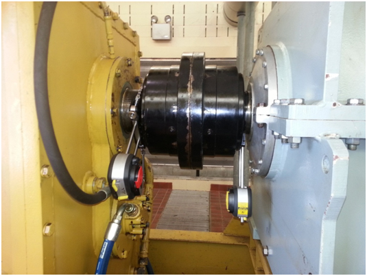
We brought a ROTALIGN ULTRA IS to the site with four sets of sensALIGN heads. Using the multi-coupling measurement feature in the ROTALIGN (available with the Expert level of the firmware), we were able to take a set of readings across three of the four couplings simultaneously using the Continuous Sweep mode in just minutes. However, since the diesel engine is disengaged from the rest of the train while rotating clockwise from the motor, its shaft does not turn with the rest of the train. This problem was overcome by uncoupling it from its clutch and using a turning gear to rotate the engine shaft separately while utilizing the Pass Mode measurement mode for uncoupled shafts across this coupling.
Although short-coupled with double engagement gear couplings, the fairly large size of each of these couplings meant we could treat them as spacer couplings since the 8-inch span between the ring gears is greater than the minimum 4″ distance between flex planes recommended to consider the coupling as a short coupling.
As the diesel engine was manually turned with a turning gear to various positions, the sensALIGN laser on the clutch shaft passed the sensALIGN receiver on the engine shaft several times during the rotation of the train. This way, the entire train alignment could be captured with just one rotation of the shafts:
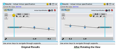
After the readings were completed, it was time to look at the results. We zoomed the view out to look at the overall alignment of the entire machine train and found this situation in the vertical plane, with the diesel engine on the left set as the reference machine:
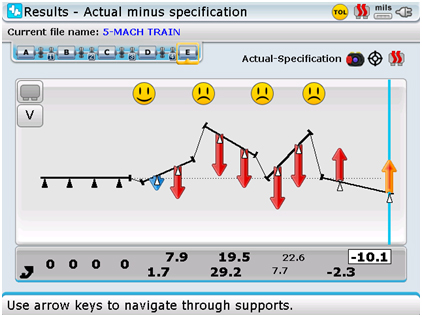
The results showed that the pump would have been dropped by nearly 20 thousandths at the left pair of feet and nearly 30 thousandths at the right pair of feet. Since it would be very difficult and inconvenient to move this heavily piped pump, we decided to explore alternatives by using the Static Foot function to set the Pump stationary as well. This meant that ROTALIGN would now draw a new optimized centerline through the two stationary machines (the engine and pump) and show us the relative positions of the remaining three machines with respect to this optimized centerline, as shown below:

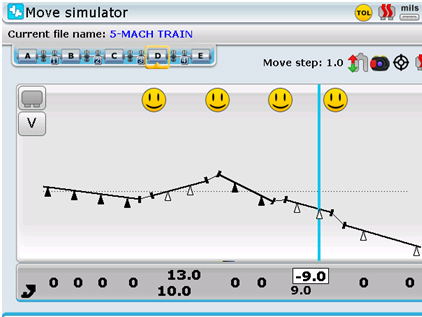
Since the motor too was large and inconvenient to move, with heavy, inflexible conduit connections, we decided to explore whether alternative shimming solutions existed to achieve a satisfactory alignment by moving only the two clutches in the train. To this end, we now opened the shimming and move simulator in the Rotalign Ultra and discovered that we could in fact achieve an excellent alignment throughout the entire train by moving just the two clutches to get into spec. The left-hand clutch (coupled to the engine) could be shimmed up by 10 thousandths at the left pair of feet (closest to the engine) and shimmed up 13 thousandths at the right pair of feet (nearest the pump.) This would achieve an excellent alignment between the clutch and the pump on the right side without compromising the already good alignment between the clutch and the engine on the left side, as illustrated below.
Next, we would pivot the right-hand clutch (nearest the motor) by raising its left pair of feet (nearest the pump) by 9 thousandths while at the same time lowering its right pair of feet (nearest the motor) by 9 thousandths as well. This would simultaneously achieve an excellent alignment of this clutch to both motor and pump. See below:
Leaving the sensALIGN components installed, we were able to monitor the alignment throughout the entire train live as the corrections were made at the two clutches. After the shimming corrections were completed the entire train was remeasured and was found to be within tolerance, with no further shim changes or horizontal moves required.
The entire alignment of this five-machine train was accomplished in just 4 hours and 37 minutes using the Multicoupling feature for simultaneous measurement across all four couplings, the Continuous Sweep and Pass Measure Modes, the Shimming Simulator, and Live Move feature of the ROTALIGN ULTRA IS. Only a tool like the ROTALIGN ULTRA IS could have allowed us to accomplish this complex task with such speed and ease.
The machine owner informed us afterward that this alignment typically scheduled at least two man-days with traditional methods and was very pleased to get his critical machine train back online so quickly, saving lots of money in the process.
by Tyler Wulterkens CRL
Purchasing a condition monitoring tool is one step in your journey to implementing a reliability program. Proper training on how to use the new technology, planning the work correctly, ensuring the work is completed on schedule and done so correctly is critical to success. Just as important is understanding the risks associated with your equipment, especially when it fails. A criticality assessment along with failure modes and effects analysis will help you understand those risks and determine where to focus your maintenance activities.
I recently spoke to a plant engineer that had purchased alignment equipment and vibration equipment from LUDECA. He had performed several alignments and collected baseline vibration data. The decision was made to start aligning machines that required maintenance and this was a wise choice to ensure failure modes were not inserted into equipment during routine maintenance activities. Unfortunately, this facility had not performed a criticality assessment on their machinery! It turns out that the plant had a catastrophic failure on a piece of equipment that was vital to the overall production processes of the plant. The first comment made was “why did we have this failure when we recently invested in alignment and vibration equipment?”
You must fully understand the risks to safety, production, environment, and profits that your equipment imposes on your facility. As you can see from the example above, not understanding these factors may lead to continued equipment failures and their undesired consequences. To ensure that you do not continue to experience maintenance failures requires that you fully comprehend the risks that each piece of equipment entails. Had this facility understood the failure modes and the (criticality/risk) impact each machine posed, they would have been able to focus their maintenance efforts where they were most needed to keep the plant efficiently operational.
As part of this endeavor, it is important to apply condition monitoring (vibration analysis and properly targeted alignment, among other things) on the equipment within your plant, because it is extremely difficult to be reliable without doing so. However, you must understand how and where to direct those efforts to ensure that unwanted risks are reduced. Understanding how your equipment can fail (FMEA), the consequences of those failures (RCM or risk assessment), and what equipment is most important to keep your plant operational (criticality assessment) are all important to ensure that your maintenance efforts are properly focused. These efforts may avoid the experience this facility had and prevent your plant from experiencing the same unwanted effects.
by Frank Seidenthal CRL
SOLAR gas turbine centering tool with X-Y tracking
The centering tool for SOLAR TURBINES is based upon shaft travel in the vertical plane. As the top knob is turned, a plunger pushes the shaft from the top position all the way down to the bottom position. The tool allows the technician to count the number of turns of the top knob to determine the amount of travel of the shaft. Upon traversing the full extent of the travel range from top to bottom, the technician then applies only half the number of turns in the opposite direction to return the shaft to the center of its vertical travel range. Performing this task with the ROTALIGN® ULTRA laser shaft alignment system allowed this job to be performed much more accurately. The laser/sensor combination takes the centering of the shaft to a new dimension by tracking not only the shaft’s vertical position but its horizontal position as well.
with ROTALIGN ULTRA’s SENSALIGN® sensor installed on the shaft.
by Carlos Bienes CRL
LUDECA’s donation of its laser alignment system to Midlands Technical College prepares students for the real world.

Matthew Lester, an industrial training instructor for Midlands Technical College, was mindful of the good that would come from the donation of equipment from LUDECA. When Midlands Tech finally received the laser alignment systems and equipment, his dream of helping students prepare for their future jobs came true. Read the rest of the blog by Plant Services Magazine.
by Ana Maria Delgado, CRL
You’ve always heard the adage, “Laser on the Stationary and Receiver (or Prism) on the Movable.” In this day and age, however, this “truism” has become obsolete. You see, the concept of the “stationary” machine, per se, is obsolete. ALL machines CAN be moved if they really need to be (no machine grew out of the ground, like a tree!), so instead, we emphasize that the laser should be mounted on the machine that is “more difficult” to move (usually the pump because of the connected piping.)
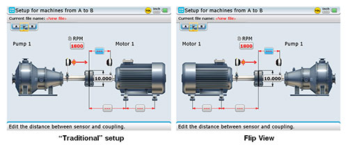
The flexibility that all ROTALIGN® (and OPTALIGN SMART® products) offer through their static feet function, as well as the ability to freely flip or rotate the view of the machines to suit your needs, means that you no longer need to concern yourself with “stationary” machines. Your real goal is to find the easiest and most expedient way of aligning your machines. In some cases, this may mean moving one pair of feet on the pump just a little to keep from having to move the motor feet a lot.
So, let’s just amend our setup statement a bit: I always say “LLLaser on the LLLeft and RRReceiver on the RRRight!” (or RRReflector, as the case may be.) This will help you to remember and keep your setups consistent. But what if your pump and motor are mounted close beside a wall, and you can only access the machines from one side? As luck would have it, that side is always “the wrong side” as dictated by Murphy’s law, with your pump on the right and the motor on the left, instead of the way you are used to seeing them. No matter! Still, mount your laser on the left machine. Now, since the Rotalign and Optalign want to move the right machine by default, you can now employ the “Flip Machines” feature, which will automatically swap the view of your machines left and right, so you can see them the way they really are in the field, and easily move the left machine now, even if you have mounted your laser on it.
If you have two equally hard-to-move machines, each of which you would ordinarily like to consider stationary (such as a heavily piped little steam turbine driving a heavily piped compressor), then it really just boils down to which machine (or combination of feet on both machines) is the most expedient to move. Again, mount the laser on the left. You can always use the static feet function to declare the machine on the right stationary and make the machine on the left movable or ask the tool to make any combination of feet movable so as to find your smallest possible moves or optimal combination of moves to solve bolt-bound or base-bound situations in the field. The ROTALIGN ULTRA products are especially versatile for this, since they let you explore fully optimized centerlines (move ALL the feet in the train), as well as under-constrained and over-constrained centerlines, to cope with the exigencies of the situations you encounter in the field.
Lastly, if you ever need to compare your alignment or your target specs to a drawing or to someone else’s report that shows the machines the other way around from the way you set up, you can always use the Rotate View functionality to look at your results from the other side. You use this feature “after the fact”—in other words, after your setup is already complete, with readings taken and results obtained, you can always rotate the view and see your results as if you had walked around to the other side of the machines.
To summarize, the concept of “stationary” and “movable” is history. Use the Flip View feature right at the beginning, when you set up, to make your setup conform to the actual situation in the field. Use the Static Feet Function to make any machine movable or stationary, and to explore “best possible” correction alternatives.
Lastly, use the Rotate View feature to look at your alignment differently, after it’s already done.
Learn how these features work in the ROTALIGN ULTRA, OPTALIGN SMART, and SHAFTALIGN® laser shaft alignment systems.
by Alan Luedeking CRL CMRP
At Enterprise Products an 8000 HP Siemens Electric Motor is short-coupled to an Ariel KBV six throw compressor. Unit was suffering from very large amounts of vibration causing excessive wear and tear on various components of the machine.

This alignment is performed using the compact magnetic brackets attached to a huge Thomas shim disk-type coupling. The shafts are turned using their 15-ton overhead bridge crane with a suitable nylon strap. The alignment was performed using the OPTALIGN® SMART alignment system and the Multi-point Measure Mode. To take readings, the unit must be turned with a 15-ton overhead crane. Since the rotation is not even and start-stop positions cannot be exactly controlled, measurements are taken at various locations along the rotation. The Multi-point Mode is ideal for this situation.
I have been using OPTALIGN SMART Laser Equipment for years. The OPTALIGN SMART makes it simple and easy to align very small equipment as well as very large equipment. We use the OPTALIGN SMART to align all rotating equipment in our facilities. The two pieces of equipment grow together within .001” to .002”. This was confirmed when a hot alignment was performed. We check alignment both hot and cold every 4000 hours of run time. The OPTALIGN SMART takes the guess work out and definitely saves valuable time.” —D. Thomas, Enterprise Products
by Tim Rogers CRL
When performing shaft alignment, the most important goal is to align the machine to within proper tolerances.
One criterion that has an impact on the tolerances that should be used is identifying and selecting the correct coupling type. In the setup shown below in Figure 1, spacer coupling tolerances were being used. However, in order to achieve a proper alignment, the alignment should have been performed using short flex tolerances.
Between the two shafts, a long coupling is used to connect them, however, the connection between the motor shaft and the spacer (left side in the picture) is rigidly coupled and has no flexible element. Thus this setup should be treated as a continuous extension of the motor shaft. Therefore, the alignment should be performed using the short flex tolerances at the flexible coupling on the right side. Spacer tolerances should only be used when the distance between the two flex planes of coupling is four inches or greater.
by Tim Rogers CRL
Happy to share two great articles by MAINTENANCE TECHNOLOGY Magazine about The Importance of Shaft Alignment and Precision Shaft Alignment For Improved Uptime:
by Ana Maria Delgado, CRL
Maritime Reporter & Engineering News • AUGUST 2014
If you operate a vessel, its machinery, without a doubt, will require alignment many times during the course of its life. When misalignment is present components will be worn, efficiency will be lost, and, if left uncorrected, mechanical failures are imminent. This translates into a strain on mechanical systems, your budget, and your peace of mind.
When speaking of alignment in marine applications, it is usually shaft alignment that is being referenced…
Read the entire article Laser Alignment – Keeping Your Machinery in Line to Maximize your Bottom Line by our client AME Solutions featuring our ROTALIGN® ULTRA laser alignment system
by Ana Maria Delgado, CRL
If non-repeatability is an issue and it is not due to the setup of the laser or ambient vibration, then it may be of interest to check the bearing clearances. This can be accomplished very easily with a laser. A little bit of information is necessary to accomplish this. We will need the following:
a) Acceptable bearing clearance and tolerances.
b) Distance between bearings.
c) Distance from the receiver of the laser system to the first bearing.
d) Rotalign® Ultra laser system.
For instance, suppose that the distance between bearings is 10 inches, the distance from the receiver to the first bearing is 5 inches, and the acceptable clearance is 4 mils. This means that with the shaft bottomed out in the bearing, there is a total of 4 mils of clearance available, or lift. With the receiver at the 12:00 o’clock position in XY-View, press the SET ZERO button. This will give you a zero reference for the values displayed on the sensor. Simply lift the shaft until it contacts the top of the bearing and record the Y value of the movement. With the above distances, we are allowed 4 mils/10 inches, (or 0.4 mils/1 inch), 10 inches being the distance between the bearings. From the receiver to the front bearing is 5 inches, so with a good bearing, we would expect to see another 2 mils/5 inches, (or 0.4 mils/ 1 inch). Add the two together and we get a total of 6 mils/15 inches. This means that if the lift of the shaft shows 6 mils of change at the receiver, the clearance is acceptable. If greater than 6 mils, clearances may be excessive.
by Ana Maria Delgado, CRL
A customer in Florida needed to do an alignment between a gas turbine and a generator. Their main issue was that the gas turbine shaft could not be rotated by hand and engineering was reluctant at that time to turn on the lift oil pumps. This customer owns and uses the ROTALIGN® ULTRA iS. We suggested using the Multipoint measurement mode in the ROTALIGN ULTRA iS in conjunction with one ALI 2.230 Magnetic Sliding Bracket for the turbine shaft and one ALI 2.112set Compact Magnetic Bracket. With the shafts uncoupled, the generator shaft could be rotated to any position, and the sensor could be positioned at any rotational position on the turbine shaft with the magnetic sliding bracket. A very big advantage of using the ROTALIGN ULTRA iS in the Multipoint mode is that thanks to the quality factor value obtained from the readings a very clear picture emerges of the quality of the data obtained while taking the readings. Any rogue measurements caused by surface imperfections in the turbine coupling can be eliminated without compromising otherwise good data. The ROTALIGN ULTRA’s Technical Note # 12 – for Non-Rotating Shafts was provided to the customer to better guide the process.
Accurate readings were obtained quickly and efficiently, resulting in many man-hours saved on this critical alignment job.
by Alan Luedeking CRL CMRP
Recently, while visiting the West Coast, I had an opportunity to get involved in an alignment with Mr. Roy Loop from The Rueck Company on a tug boat being built on the Columbia River near Portland, OR. This tug will be put into service halfway around the world where it will be towing and docking ships into and out of ports. A failure in this remote location would make repairs extremely expensive for the owner, not only due to its service location but because of lost revenue from the vessel being out of service.

Knowing this, the tug boat’s owner wanted to verify the alignment of the drive lines (both port & starboard) to ensure they were within the required alignment tolerances before putting the vessel into service.
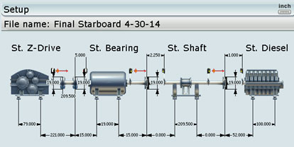
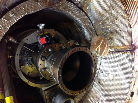
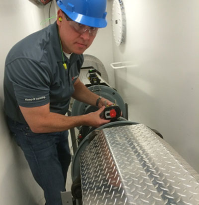
The interesting about this application is that the driveshaft goes through a bulkhead so there is no line of sight between the Z-drive and the diesel engine. In the image below you can see the bulkhead. The diesel engine is on the other side of this bulkhead. In this picture, we are setting up the receiver on a 17-foot jackshaft.
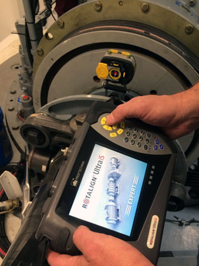
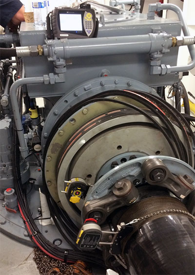
Fortunately, we had a ROTALIGN ULTRA iS Laser System (with Expert level firmware). This firmware gave us the capability to set up multiple laser heads on all of the drive train components and thereby measure the entire machine train with just one rotation. Despite the fact that two sets of lasers and receivers were on the other side of the bulkhead, we could still establish communication via the powerful Bluetooth module built into the laser equipment. The ROTALIGN ULTRA iS is the only system on the market that is capable of performing this alignment measurement across multiple couplings simultaneously with just one rotation of the driveline. In order to rotate the shafts, the drive train typically needs to be cranked by hand using a ratchet on the diesel’s flywheel. This is extremely tiring, time-consuming, and difficult to do. If you had to “crank” the diesel for each of the four couplings one at a time, the job might take several hours just to take the readings. With this alignment set-up, we were able to use the ROTALIGN’s unique Continuous Sweep measurement mode, so there was no need to stop and start at any specific measurement location.
Three sets of readings were taken to verify repeatability using the ROTALIGN’s unique measurement table. This measurement table allowed us to view each of the coupling’s three readings in a table to verify repeatability and (if desired) average these readings together. Each set of readings was accomplished with just a single turn of the shafts with less than 100 degrees rotation. The entire alignment data collection process (all three sets of readings) was accomplished in just a few minutes.
When making live moves/corrections, the ROTALIGN ULTRA iS Expert allowed us to see the alignment condition at each coupling simultaneously in real-time for both the Vertical and Horizontal directions. This is another unique capability that is extremely important, since, when one component of the drive train is moved, it affects the alignment condition at the other couplings. Having this capability is a huge time saver, reducing the job sometimes from days to just hours.
AS FOUND results:
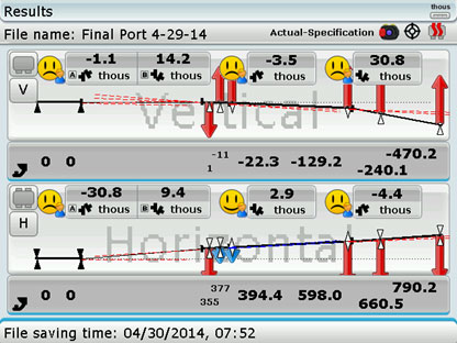
As LEFT results:

The alignment tolerances from the coupling manufacturer were given in degrees of angularity rather than as gap differences at the coupling. To verify that the alignment was within the coupling manufacturer’s tolerances, the Rotalign Ultra allowed us to instantly convert the measured alignment condition to display the angle in degrees rather than as a gap. Below is the final reading in degrees:
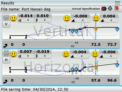
The alignment was accomplished within alignment specifications, as shown by the smiley faces. The ship’s owner was confident that alignment would not be an issue and gave the green light to put the tug into service.
by Frank Seidenthal CRL
Some weeks ago, a compressor manufacturer contracted us to perform ROTALIGN® ULTRA laser alignment training at their testing facility. During the training, the millwrights mentioned that they had a need to align the gearbox shaft to the compressor bores during the assembly process before the compressor shaft was installed. Since my ROTALIGN ULTRA also features the CENTRALIGN® ULTRA bore alignment option, I offered to train them on this interesting application.
The objective was to perform the alignment so that when the compressor shaft is put in, it is already within tolerance and the compressor is immediately ready to be tested. This means that the millwrights need to align the static centerline of the bores of the compressor to the rotating centerline of the gearbox shaft. This is a challenging application that the ROTALIGN ULTRA with CENTRALIGN ULTRA can handle with ease (see Figure 1.)
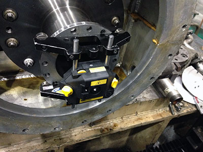
Fig. 1: Laser mounted on Rotating Gearbox Shaft
We first covered the key concepts of what it means to do a bore alignment. Hands-on exercises illustrated the differences between aligning with a static laser beam through the bores and a rotating laser setup on the gearbox shaft. Once on the shop floor, we were able to measure a compressor’s bores with respect to the gearbox shaft within 45 minutes, start to finish including setup time for both stages of the measurement (see Figure 2.)

Fig. 2: Receiver with Bluetooth module in compressor bore
The millwrights seemed thrilled with the simplicity of the process, compared to their current approach, which involved using a complicated bracket system to support dial indicators, sometimes taking up to a day to obtain accurate measurements.
The customer purchased the ROTALIGN ULTRA with CENTRALIGN ULTRA option and now obtains accurate and repeatable measurements within an hour, without depending on the skill level of the operator. This has freed up manpower, save time, and a great deal of money during the compressor assembly process.
by Adam Stredel CRL
“Thermal growth” often refers to the change in machinery positions as a machine runs from startup to operating conditions (or vice versa). Machinery positional change can also be caused by dynamic forces, pipe stress and other factors. Compensating for thermal growth is necessary because the machine will be misaligned during operating conditions if it is not. —Daus Studenberg, Applications Engineer – LUDECA, Inc.
 Thermal Growth and Machinery Movement Crash Course Video
Machinery movement and thermal growth are two of the main issues that affect operation and life of machinery. Watch our crash course video and see how continuous monitoring of positional change can eliminate checks and calculations and provide an exact solution.
by Ana Maria Delgado, CRL
If you have a vertical flange-mounted motor and need to shim it to correct angularity, our laser systems provide the following handy options to accomplish this:
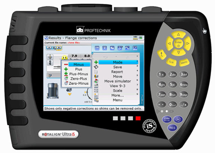
How to decide which option to use?
MINUS: If you have plenty of shims already there, you can select this option to minimize the number of shims used, since the correction will be accomplished by removing (subtracting) shims.
PLUS: if you have no shims between the motor flange and support flange, to begin with, you can select this option to affect the correction by only adding shims.
PLUS-MINUS: With this option, exactly half of your corrections will be positive (adding shims) and half will be negative (removing shims). This option is very handy if your pump impeller hangs from the thrust bearing in the motor and you do not want to change the pump shaft’s axial position. The plus-minus option makes your pivot point the shaft centerline itself so that the correction will have no z-axis effect on the shaft from shimming at all. This also minimizes the absolute amount of shimming needed.
ZERO-PLUS: This option means all positive shimming but forces one bolt location to be zero (no correction). This is very handy when the bolt circle diameter is the same as the flange diameter, or you already have some shims between the flanges to start with and want to minimize the amount of shimming needed.
ZERO-MINUS: This solution is similar to ZERO-PLUS but in the negative direction, meaning all corrections call for removing shims, with one bolt position at zero correction. This is handy if you have lots of shims already between the flanges and want to reduce these while minimizing the corrections needed.
by Carlos Bienes CRL
Recently our customer, Metropolitan Sewer District of Greater Cincinnati (MSD), shared with us their successful findings with OPTALIGN SMART. Their Maintenance Department utilizes a variety of predictive technologies and preventive strategies to support their mission of improving equipment reliability and reducing downtime.
They are committed to extending the life cycles of their assets with their already established laser alignment program.
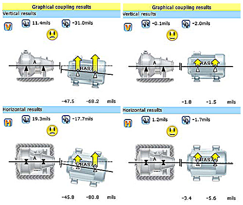
Their recent analysis started when their Maintenance Crew Leader downloaded and interpreted the alignment test results. Planned scheduled follow-up work orders, baseline testing, realignment, and retesting revealed that one of their pumps showed excessive shaft misalignment between the pump and motor in both the horizontal and vertical planes. As-found test results showed the equipment out of vertical alignment by 11.4 thousandths, and horizontal alignment off by 19.3 thousandths. The maintenance staff proceeded to generate a follow-up work order to realign the pump and motor.
Follow-up Actions:
Plant Maintenance Workers uncoupled and realigned the components, using jacking lugs and shims to correct the misalignment. After realignment work was completed, they installed a new coupling and performed follow-up retesting with the OPTALIGN SMART tool, verifying that the components had been aligned within the required specifications.
They have now proven that equipment misalignment will cause mechanical seal failure and premature bearing wear, resulting in equipment failure and unexpected downtime. By testing and aligning equipment proactively, MSD Maintenance personnel were able to identify and correct misalignment problems before irreversible damage occurred and assets would have had to be replaced. The total work order cost for testing and realigning this asset was $154.70. The purchase price of a new pump of this type is $2,456.00, resulting in a minimum cost avoidance of $2,301.30, not including labor costs to remove and reinstall the equipment.
Special thanks to our friends at Metropolitan Sewer District of Greater Cincinnati for sharing their success with us and reminding us once again that there are just No Excuses for Misalignment.
by Yolanda Lopez
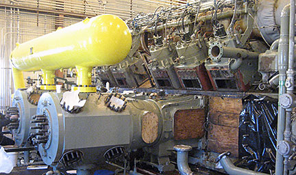 The bore alignment of the crosshead guides in a large compressor driven by a 4, 000 HP engine was thought to be a problem after this compressor, which had run trouble-free for 30 years started having problems. Methods used before involved checking with a machinist’s level only. The crosshead guides have an approximate diameter of 20”.
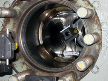
The ROTALIGN® ULTRA laser shaft alignment system with CENTRALIGN® ULTRA bore alignment add-on module was brought in and five cylinders were checked. Each cylinder to crosshead guide measurement took about 1 hour to complete, including setup and measurement. Most fell within five-thousandths of an inch of offset. One cylinder and crosshead guide were found to be out of alignment. This cylinder was measured to be lower than the crosshead guide by 70 thousandths and 65 thousandths at the inboard and outboard ends respectively. This result could not have been measured with the machinist’s level. Also, with the level no ability to check side-to-side misalignment exists.
Some wear was detected, so we were able to avoid the “bad” spots with the CENTRALIGN pointer bracket.
Repeatability was typical, at under 0.5 thousandths. The low Standard Deviation (SD) values provided by the ROTALIGN confirmed that measurements were not hitting damaged sections and were highly reliable. SD is not available with tight wire measurements, which can lead to having incorrect center readings. In addition, obstructions and confined spaces make tight wire setup and readings extremely difficult.
The ROTALIGN ULTRA with CENTRALIGN helped reveal problems with 100% confidence in measurements and with excellent repeatability, in a fraction of the time that would otherwise have been required using other, less accurate and less reliable methods. This resulted in great savings for the customer.
by Daus Studenberg CRL
The customer needed to align a boiler feed pump to a fluid drive.
Before doing so, we took care of the simple but often-ignored pre-alignment checks, including a thorough cleaning up of the area around the machines. The area was a mess to start with, and cleaning up allowed us to check for soft foot and start making moves immediately after taking readings, without delays.

Some of the essential clean-up and preparation tasks we performed were:
- Clean up the work area.
- Remove jacking bolt fixtures and wire brush the corrosion off them.
- Cleaning and greasing the hold-down bolts and jack bolts with white lithium grease.
- Drilled and tapped new holes in the base to add jack bolts where there weren’t any.
- Replaced dirty used shims with new precut stainless steel shims.
- Rough aligned the pump so its anchor bolts were centered in bolt holes of the feet.
This preparation work saved much time on the actual alignment, and more importantly, ensures that the next time this job must be performed the jackscrews, base, and anchor bolts will be in good condition, allowing the machines to be quickly and accurately realigned.
by Carlos Bienes CRL