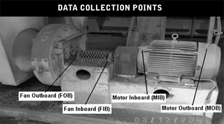
 To facilitate the initial learning curve, a labeling system was implemented to help technicians collecting data identify bearings that were part of the initial survey. These descriptors were laminated to prolong their life in the unfriendly environment of a typical cement plant. Standard locations for data collection needed to be understood since labels would become difficult or impossible to read over time.
On-the-job training included an understanding that readings collected on the drive motor bearings needed to be collected from the grease fitting on the non-drive end and from the upper portion of the end bell housing on the drive end. On driven equipment bearings, where direct access was possible, the ultrasound readings were to be taken in the horizontal plane directly from the bearing housing. (Note: with ultrasound, it is not necessary to record data from multiple planes on the same bearing). Technicians were trained to take ultrasound readings as close to the bearing as physically possible while respecting personal safety.
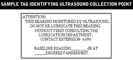
This simple label proved important to the integrity of the pilot project to prevent greasing from well-intentioned lubricators.
by Allan Rienstra - SDT Ultrasound Solutions
Like any job, there is a right way and a wrong way to do things. Simply listening to a bearing with an ultrasound device that gives no quantitative feedback is a recipe for disaster. The audible feedback is too subjective to draw any comparative conclusions. No two people hear the same and there is no way to remember what the bearing sounded like a month ago.
The third mistake is depending solely on subjective ultrasound data when precise quantifiable data is available.
Always use an ultrasound instrument with digital decibel metering. Better still, use a device that provides multiple condition indicators. Max and Peak RMS decibel measurements indicate alarm levels and greasing intervals while Ultrasonic Crest Factor provides insight about the bearing condition in relation to its lubricant. Crest factors help us differentiate between bearings that need grease and bearings that need to be replaced.
Download the Ultrasound Lubrication Technician Handbook
by Allan Rienstra - SDT Ultrasound Solutions
The second mistake we should all avoid is adding too much, or not enough grease. Too much grease builds up pressure pushing the rolling elements through the fluid film and against the outer race. Increased friction and temperature dramatically shorten the bearing’s life. Not enough grease will have the same life-shortening effect.
How do we know when just the right amount of grease has been added? Ultrasound of course. Listen to the bearing and measure the drop in friction as the grease fills the bearing cavity. As the decibel level approaches normal baselines and stabilizes carefully slow the application of lubricant. Should the decibel level begin to increase slightly, STOP! The job is done.
Download the Ultrasound Lubrication Technician Handbook
by Allan Rienstra - SDT Ultrasound Solutions
Lubricating a bearing once per week or once a month may seem like a sensible thing to do. After all, performing scheduled maintenance at regular periods is an age-old concept ingrained in each of us early on. Even OEMs still advise best practices based on time intervals to ensure maximum asset lifespan.
The problem with any blanket solution is that they ignore the effects of variables.
Two motors may be the same out of the box but end up in entirely different situations. While one lands in a hot and humid climate, another could be installed in a cold and arid climate. One may be used in a high-speed low load application while another at low speeds but with frequent starts and stops.
It is irrational to expect the maintenance needs of one to be the same for another when the conditions they operate in are so different.
Bearings need grease for one reason only; to reduce friction. As long as the lubricant is performing that service well, there should be no need to change it. Yet we frequently do, with catastrophic results.
Re-lubricating a bearing just because your calendar told you “time’s up!” is the first mistake. Monitor ultrasound friction and know when it’s the right time to grease.
Download the Ultrasound Lubrication Technician Handbook
by Allan Rienstra - SDT Ultrasound Solutions
It can be argued that lubricants are the lifeblood of equipment. It is extremely difficult to assure equipment reliability when lubrication integrity is not maintained. The key is to keep the lubrication system clean, cool, and dry.
According to the Arrhenius Rate Rule, every 18-degree (F) increase in oil temperature in operation reduces oil life by half. Excessive lubrication temperatures can lead to additive depletion, oxidation, varnishing, hazards, corrosion, increased frequency of oil changes, and more. All of this leads to reduced equipment reliability and increased costs.
Reduced operating temperature is one of the many benefits associated with proper machinery alignment. This in turn will help you reduce the operating temperature of the lubricants (lifeblood) within your equipment. Best practice equipment reliability includes proper equipment alignment. Your best practice lubrication efforts should include making sure your equipment is operated within proper alignment tolerances. Doing so will help you maintain the “cool” required to ensure that the lifeblood of your equipment is protected.
by Trent Phillips CRL CMRP - Novelis
Today’s more evolved ultrasound data collectors present results that take reliability practitioners beyond the single decibel. Using only an overall dB value may indicate something inside the machine has changed since the last readings were taken. But it provides no additional insight to determine what type of defect may be present.
Moreover, a single dB only provides a useful trend if the inspector has control of the acquisition time during data collection. Acquisition time needs to be adjusted in concert with the speed of the machine. More time for low-speed applications and less for high. The aim should be to capture a minimum of 2-3 full shaft rotations.
The SDT270 takes inspectors beyond the single decibel by presenting ultrasound data in terms of machine condition. We call them Condition Indicators and there are four (RMS, Max RMS, Peak, and Crest Factor (CF)) and are abbreviated as 4CI. Ultrasound identifies defects in machines when those defects produce one or more of the following phenomena: FRICTION, IMPACTING, or TURBULENCE (FIT).
Some examples:
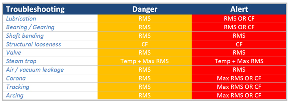
- A bearing that requires lubrication will present higher levels of friction. Therefore, an RMS danger alarm will be triggered at 8 dB and an RMS/CF alarm when severity increases.
- A bent shaft produces higher levels of friction and therefore presents danger and alert warnings with the RMS condition indicator.
- Electrical defects such as arcing, tracking, and corona are first alarmed with the RMS condition indicator and severely alarmed with Max RMS and CF.
- A faulty steam trap is detected with an elevation in Temperature and Max RMS.
Traditional ultrasound is useful for trending decibel levels that alert us when machine condition changes. Evolved ultrasound goes beyond the single decibel to recruit Condition Indicators that help inspectors determine the type of defect that is creating the alarm. SDT’s Four Condition Indicators demonstrate how ultrasound must be used for both defect alarm and identification.
by Allan Rienstra - SDT Ultrasound Solutions
Reposted from RELIABILITYWEB®
- Assemble a team and identify applications for a program
- Justify needs by recognizing key areas where improvement can be benchmarked
- Set written goals for the program
- Establish how ROI will be measured
- Purchase quality ultrasonic inspection equipment
- Invest in certification training at both management and user levels
- Choose a leader to technically carry the program forward
- Establish a system to reward the successes
- Frequently review the progress as part of regular meetings
- Ensure everyone involved is 100% mentally invested in the program’s success
Tip from Hear More: A Guide to Using Ultrasound for Leak Detection and Condition Monitoring by Thomas J. Murphy and Allan R. Rienstra.
To learn more about airborne ultrasound, download a chapter preview of Hear More.
by Allan Rienstra - SDT Ultrasound Solutions
Have you ever been asked “How much longer will it run” or “Can we make our production schedule” or other ‘crystal ball’ type questions? These types of questions can be very difficult or virtually impossible to answer. They often place a reliability professional in a difficult position.
Some future indicators are (or should be) available to the organization that will help you answer the above questions when asked. Four of those indicators are:
- Preventive Maintenance (PM) Completion Rate
Low PM completion rates directly correlate to increased future equipment maintenance work. High PM completion rates mean that needed equipment maintenance is being completed and future maintenance issues will be avoided. - Ready to Work Backlog
This is an indicator of preparedness and efficiency to complete maintenance work. - Outage Schedule Compliance
This is a very important metric to track and is an indicator of future maintenance work. A lack of adherence to outage schedules creates deferred equipment maintenance. This results in increased risks and the likelihood that equipment performance will decrease at a future time, leading to lower capacity, increased downtime, and greater expenses. - Equipment Asset Health Reporting
Proper utilization of condition monitoring technologies like vibration analysis, IR thermography, lubrication analysis, ultrasound, and others are a proactive strategy to ensure that hidden failures become known and corrected before they result in equipment downtime or other unwanted consequences. Tracking these indicators together can provide insights into future asset health. A lot of “red” assets from these technologies will result in future unwanted equipment maintenance and unwanted downtime if corrective action is not taken. Additionally, this can be used to help prioritize equipment maintenance efforts if a good critical equipment ranking system is in place.
by Trent Phillips CRL CMRP - Novelis
All machines and their components will exhibit wear at some point. This can lead to loss of function and require corrective action.
Wear particles are one of the most common sources of equipment reliability problems. They indicate that the oil is unfit and unreliable for operation in the equipment and will lead to damage to the equipment. These particles can give an insight into the type of equipment problems as well. The characteristics of wear are specific from machine to machine.
A facility in Texas lost key personnel in their condition monitoring program and experienced a gearbox failure. The plant was in need of a true online monitoring system for small and large particle quantities. They purchased the WEARSCANNER® oil particle distribution solution as a result. The WEARSCANNER solution not only counts and classifies but also has the ability to count low and high particle flow speeds which is of value to the customer.
The customer was able to adjust the different size classes in accordance with ISO 16232 and have the data fed directly into their control system.
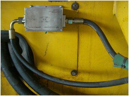
One of the keys to equipment reliability is keeping lubrication clean, cool, and free of moisture. This facility purchased the WEARSCANNER solution so they can actively monitor the cleanliness of critical equipment.
by Alex Nino CRL
Guest post by Dave Tiffany, Reliability Specialist for Pioneer Engineering
If you have a gearbox with a manufacturer’s nameplate instructing you to use the American Gear Manufacturer’s Association (AGMA) #4 viscosity oil at a given operating temperature, or if it specified a 750 SSU viscosity oil, would you know exactly what viscosity oil you need? If your grease application specified a base oil viscosity of 220 cSt for a given operating temperature would you know which of your greases might fit that specification, if any?
Does it really matter? Oil is oil, grease is grease, and more is better, right?
WRONG!
The importance of proper oil viscosity in your large array of equipment and the varying lubrication regimes they present is one of the most important maintenance practices one can focus on in their facilities. Viscosity is the most important physical property of a lubricant, and viscosity is the most important specification for a lubricant. Along with this, viscosity is the easiest thing to mess up!
A simple definition of viscosity is the thickness of an oil. While this is the most common understanding of viscosity, a more technical definition of viscosity is a measurement of the oil’s internal resistance or its resistance to flow by gravity. Viscosity is what carries the load, separating surfaces in relative motion from touching, thus reducing friction and wear, extending equipment life.
Viscosity should always be measured at a given temperature. Normally viscosity is inversely proportional to temperature, meaning as the temperature of an oil increases, its viscosity generally will decrease.
Stating an oil’s viscosity is found in many different formats depending on the application. The International Standards Organization (ISO) is the universally accepted method for stating oil viscosity (ISO VG) throughout the industry (ISO 3448). This ranges from an ISO VG 2 to an ISO VG 3200. ISO VG is stated at 40°C.
AGMA specifies grades of an oil’s viscosity for industrial gear applications, also at 40°C. The AGMA uses a #1 through #8A designation.
SUS – or – SSU is not in use much anymore, but you may still find it referenced on an older gearbox nameplate or an OEM (original equipment manufacturer) manual. This stands for Saybolt Universal Seconds – or – Saybolt Seconds Universal, you’ll see it stated either way.
Society of Automotive Engineers (SAE) Crankcase and SAE Gear classifications are different yet. 0W, 5W, 10W, etc., and straight weights 30, 40, and 50 are designations for crankcase oils, while 70W to 85W and 80 to 250 are designations for automotive gear oils.
If all of this is making sense, I commend you. You are likely on top of your game and know exactly which oils and viscosities belong in each application throughout your facility. But if this sounds like a foreign language that you do not understand, it’s okay, as long as you now realize that your equipment may be in jeopardy of shorter life cycles and there is potential for cost-saving improvements that will greatly enhance your equipment’s reliability.
by Ana Maria Delgado, CRL
Engineering advancements have resulted in many different types and grades of lubricants being available for equipment maintenance. Unfortunately, the risk of improper selection and mixing of lubricants has increased as well. Mixing different types of lubricants (grease and oil, etc.) within a machine is one of the most common equipment reliability problems. Doing so can result in unanticipated chemical reactions and equipment failures.
Proper labeling is a method to help ensure that the correct type of grease or lubricant is being injected into your equipment. Color-coded labels with proper lubricant identification markings should be placed on the Zerk fitting or near any lubrication entry point on a machine. Grease guns and lubricant containers should have the same color identification and markings as well. This simple process can assist in eliminating lubricant contamination and thereby prevent one of the most common reliability problems today.
by Mickey Harp CRL
Guest post by Brad Loucks, Mechanical Engineer at Pioneer Engineering
When discussing machine lubrication techniques and associated maintenance tasks with industry personnel, I often hear the same story; “Once a month, we fill it up until it’s full.” This story can unfold further to reveal that every piece of machinery under such a program receives the same type of lubricant with no considerations made to temperature change, operating conditions, load requirements, and duty cycle. Technology has come a long way over the past several decades in every corner of the modern world and machine lubrication and oil analysis is no exception to this evolution. It has been discovered that choosing the right lubricant for the application significantly prolongs machine life and maintains the overall health of rotating equipment in use today.
To further illustrate this point, just consider how much thought is given to the type of oil used in your car. You won’t find a can of automobile oil in the store that is simply labeled, “Oil”. Instead, you will find several types of oil that are specifically designed to resist large viscosity changes with changing temperature. The ability to resist significant viscosity change is depicted using the nomenclature, “10W-30”, or “5W-40”, etc. A common misconception is that the “W” stands for weight. Instead, the “W” stands for “winter”, and the number that precedes it represents the oil’s ability to resist thickening when the temperature is 0° Fahrenheit. Similarly, the second number represents the oil’s ability to resist thinning in an environment where the temperature is 100° Fahrenheit.
As you can see, the operating environment and temperature play a big role in choosing the right lubrication to extend the life of an automobile engine. In an industrial setting, machine lubrication plays an even larger role with proportional consequences and benefits to the amount of thought and detail given to choosing the right lubrication.
Recent advancements in technology now provide us with additional tools to collect and analyze oil samples in rotating machinery. In doing so, maintenance technicians are able to better understand the present health of their equipment as well as make determinations for further maintenance tasks to be performed. The difference between this story and the “Once a month, we fill it up until it’s full” story, is that we now have the ability to schedule maintenance tasks based on condition, instead of relying solely on a time trigger. A proper machine lubrication program enables us to recognize the root causes of machinery failure due to improper lubrication. A successful lubrication program also incorporates methods for identifying lubricant contamination and implements the best practices in lubricant storage, handling, and dispensing. By introducing these condition-based methods of scheduling maintenance tasks, machinery health is better managed, saving time and money.
by Ana Maria Delgado, CRL
Ingression can be defined as going in or entering, a right or permission to enter, or a means or place of entering. It is important to understand, recognize, detect and reduce the effects of particle ingression. Doing so will have a very positive effect on your maintenance and reliability efforts.
Dirt is often the root cause leading to bearing damage and reduced equipment reliability. If not monitored correctly, ingression can lead to unexpected failures resulting in high maintenance and inventory costs.
When measured in the Moh’s Hardness scale, dirt is typically more abrasive than the bearing material. This leads to pitting and other damage to the bearing that reduces the life of the equipment. It’s really quite simple: under great load, something has to give and it’s usually the bearings, gears, pump impellers, etc. Our goal should be to remove contaminants from the lubricant to our target cleanliness before placing it in our equipment. Doing so will increase our equipment reliability.
by Pete Oviedo Jr
Guest post by Kasey McClain, Mechanical Engineer at Pioneer Engineering
Everyone knows that lubrication is crucial to the life of a bearing. Two common types of bearing lubrication are grease and oil. I commonly see oil bath lubrication and oil mist along with grease lubrication. One of the biggest problems that I have encountered with greased bearings is over greasing. When installing a new bearing assembly, it is important to note whether the bearings are pre-greased by the manufacturer. Over greasing will not allow the heat to dissipate from the bearing which will cause the bearing to expand and cause a tolerance stack-up which may then show bearing defects. This may also cause an existing defect to progress, decreasing the life of the bearing. With an oil bath lubrication system, too much oil can be just as detrimental as too little oil.
With too little oil, the slinger ring, or whichever component carries the oil, will not be submerged in the oil and will not be able to lubricate the necessary components. With too much oil, some of the components may not get the lubrication necessary. Oil mist systems have been shown to eliminate the issue of too much or too little oil.
However, running the mist system low on oil will cause the components to not be lubricated. Also, the oil misters can become clogged which would lead to a lack of necessary lubrication. This is why regular lubrication monitoring is necessary to keep equipment running smoothly for as long as possible. Attention to detail is essential in all aspects of machinery maintenance.
by Ana Maria Delgado, CRL
The Finger as a Sensor and Other Things That Are Of Utmost Importance!
Toyota did a study to find out why some equipment failed prematurely. They found that something like 80% of premature equipment failures could all be traced to three rather simple causes; causes that could have been prevented or remediated before they led to equipment breakdown. What were the three culprits?
a. Looseness
b. Improper Lubrication
c. Contamination
All three of these can be addressed by the vibration analyst during collection and analysis.
Looseness can be detected with a vibration analyzer. When you see looseness, use your finger as a sensor and run it around the interfaces of the bearing pedestals, housings, and foundations. It is surprising how sensitive one can be to the phase difference of shaking parts that have become loose. See that it is remedied before it causes catastrophic failure.
Inadequate lubrication can be detected by Shock Pulse. If you are taking high-frequency acceleration readings it will cause a raised noise floor. This one is best avoided altogether by a well-planned and supported lubrication program. Often, by the time-poor lubrication is detected, a considerable amount of damage has already been done. An electric motor’s winding insulation breakdown rate is doubled for every 18° F rise over 165° F. This is why motor cooling fins are actually for cooling and not for holding dust, grime, or whatever. Contamination is an important condition to monitor via a manual input point for each machine area. Add it to your route. Report equipment covered in whatever foreign matter your plant has lots of so it can be properly cleaned before damage is created.
Focusing attention on the three areas above will definitely create value for your company.
by Mike Fitch CRL
Combine vibration monitoring and ultrasound for more cost-effective predictive maintenance
The best overall machinery monitoring program is one that utilizes multiple, integrated monitoring technologies.
In brief:
- The best overall machinery monitoring program is one that utilizes multiple, integrated monitoring technologies that are well-suited to detect expected failure modes.
- One goal of PdM is to determine how much time is left before a machine will fail, so plans can be made to minimize downtime and damage while still getting the most useful life from the machine.
- An application where ultrasound and vibration work well together is a mechanical inspection.
Reliability-centered maintenance programs are most effective and most profitable when a variety of appropriate technologies and tools are used to complement one another. Vibration analysis and ultrasound are as complementary as two sides of the same coin. Ultrasound is a useful monitoring tool, capable of detecting failing rolling element bearings and over-and under-lubrication conditions. The best overall machinery monitoring program is one that utilizes multiple, integrated monitoring technologies that are well-suited to detect expected failure modes. For low-risk machines, vibration analysis can be performed by a mechanic or operator using a vibration data collector or vibration meter. For machines of higher criticality, a certified vibration analyst should use advanced vibration data collection and analysis hardware and software.
Read my comments in this valuable PLANT SERVICES article.
by Trent Phillips
The Hibbing Taconite Company, managed by Cliffs Natural Resources of Hibbing, MN, won UPTIME Magazine’s Best Lubrication Program award. At the heart of their condition monitoring efforts is the Oil Analysis component of their lubrication program, key to helping them identify problems at an early stage of failure.
During the first phase of the program, which they called “First Evolution”, reliability engineers were trained as Level I Machine Lubrication Technicians (MLT1). Thereafter, dedicated lubrication mechanics were assigned to the plants to monitor the condition of the oil. They engaged with their vendors to identify needed parts and reviewed their planning, scheduling, and work execution. They selected critical equipment on which to prove the concept.
During Phase 2, MLT1 training continued, including lubrication mechanics and supervisors. Critical equipment underwent lubrication upgrades with the addition of desiccant breathers, sight tubes, sample ports, and quick couplers for filtering, allowing for safer filter changes and reducing cross-contamination risk.
Today, 80 employees have been MLT1 trained on machinery lubrication and basic oil analysis. Employees are fully engaged and enjoy wholehearted management support as significant consumption reduction was realized. Management views the program as an investment.
During their presentation at the IMC-2012 International Maintenance Conference, Reliability Engineer Dan Lerick shared that in certain applications, they have proved a 3.5% energy reduction by switching to synthetic gear oil, which also extended oil drains from 5 to 15 years. Another positive was the switch to synthetic engine oil where they observed a reduction in fuel usage and fueling time, with an extension in engine life and extended drain and maintenance intervals. Overall ROI was under 1 year!
In addition to their award-winning Lubrication Program and as part of their reliability efforts, the company uses CMMS software and other Predictive Maintenance technologies such as Ultrasonic examination, Laser Alignment with ROTALIGN ULTRA, etc. Learn more.
Congratulations to Dan Lerick and his team for this award and a job well done!
Program Highlights
1) Fluid Analysis consolidated across all Cliff operations. They now use a single oil lab after carefully ranking and comparing sample results from eight different labs. The benefit was consistency and the ability to review and compare data.
2) For Fluid Sampling, they developed sample standards per equipment specs, installed sample ports, and trained personnel on how to collect samples. Their CMMS system controls their sample frequency.
3) The use of Grease Systems and Grease Routes wherever possible along with ultrasonic technology on motors.
4) Implementation of condition monitoring (CM) via oil moisture sensors and CM sensors for real-time monitoring. The immediate benefit was a reduction in overall site oil consumption by removing water contamination.
5) Cleaner and safer fluid changes with the use of dedicated Lube Carts to eliminate drips and spills.
6) All machines were tagged with machine identification and lubrication information to reduce mixing and cross-contamination.
by Ana Maria Delgado, CRL