Management and co-workers do not always understand why Condition Monitoring (CM) Analysts spend so much time in an office looking at a computer screen. What are they doing? What does that have to do with condition monitoring activities, equipment repairs, and reliability efforts? Why are they not in the field collecting data?
Why are they not working on equipment maintenance? Unfortunately, these misconceptions often result in a perception that CM Analysts are not doing their job and they are pulled back into routine maintenance activities or assigned other work tasks.
The reality is that four critical steps must be consistently completed by a CM Analyst for the program to be successful. First, valid data must be collected with the CM technology at proper measurement intervals. Second, the collected data must be properly analyzed. Third, the findings must be promptly reported in a meaningful way to those responsible for planning, scheduling, and completing the CM results. Fourth, the database(s), measurement methods, and equipment information must be constantly updated. Additionally, routine research is required to ensure that proper measurement and analytical techniques are being applied, needed information is available, etc.
Successful completion of the critical steps outlined above requires time in an office environment using a computer. Not allowing your analyst(s) this necessary time will ensure failure and result in needless reliability issues. An old rule of thumb is that for every hour a CM analyst spends in the field it will require an hour in the office processing that data, reporting the findings, etc., as explained above. The time in the office can vary depending upon how well the CM database is set up with proper alarms and measurement criteria. In addition, the analysis software, CMMS software, and other resources can be a critical factor in determining how much office time is required.
The point is that an analyst requires office time to properly process, report, and maintain his CM efforts.
Otherwise, the CM program is certain to fail. Provide time for the analyst(s) to do the job being asked of them or don’t be surprised when these efforts fail.
by Trent Phillips CRL CMRP - Novelis
As Published by BIC Magazine December 2015 issue
A world-class reliability program is not achieved overnight, yet you must start somewhere. Your first step is to vest your entire human capital in its success. Reliability is a culture, not a goal, and it flows from the top down.
Therefore, executive sponsorship with integrity and enforcement is a must. Obtain buy-in to the culture of reliability from everybody in your organization, or the effort is doomed to fail. Start with this realization, and your reliability effort will ultimately succeed, and you and your stakeholders will reap its rewards.
The reliability workflow must be well organized and underpinned by a Computerized Maintenance Management System (CMMS). Let’s look at how it works in a world-class program.
Ultrasound analysis detects a bearing fault in a critical motor early in the P-F curve. The analyst enters this data in the CMMS and trends it. The analyst decides to request a work order with recommendations. This is Stage 1 in the work order process.
The work order is now reviewed by both maintenance and operations, thereby ensuring buy-in from operations as well. This is Stage 2. This review process ensures only truly needed or valuable work is approved. Also, older open work orders can be combined with this one to further streamline planned activity on the asset. For instance, an earlier work order was created to align the machine, but the work was never carried out, resulting in the bearing damage the ultrasound analyst has now detected. The review process would catch the older open order and add it to the present order. This would prevent the millwright from going out to align the machine tomorrow only to have a repair technician go out the following week and repair the motor but do no alignment on it. This review process tries to eliminate inefficiency, duplication, and detrimental work sequences.
Stage 3 assigns the work order to the maintenance planner for action. Only approved and truly necessary work enters the planner’s backlog. The planner ensures work is properly prioritized. Two things are needed: The criticality ranking of the asset (ascertained from systems’ criticality analysis) and its operational criticality. Both of these factors can be multiplied together to create a more accurate prioritization of the workflow. The planner creates a new work plan if needed and should consult with maintenance supervisors and technicians; valuable insights may be gained into what parts, tools, and equipment should be specified in the work plan. Next, the planner orders the maintenance, repair and operating materials (MRO) spares, and tooling required to complete the job and verifies the parts are available and kitted (best practice). The planner should not concern himself with scheduling.
Now on to Stage 4: assignment to the scheduler. The scheduler allocates the HR and necessary time to accomplish the task, with a cushion for unforeseen complications. He too should consult with the maintenance supervisor and technicians to obtain cooperation and buy-in to the schedule. Coordination with operations is crucial. Operations “owns” the equipment and must sign off on the schedule to bring the asset down.
Stage 5 assigns the order to the appropriate maintenance and electrical supervisors, who in turn assign specific tasks in the work plan to their respective repair technicians, electricians, and millwrights, and verify MRO spares has delivered the parts kit to the proper location.
Now the work order enters Stage 6: the work execution phase. Once the technicians have completed the work, they report to their supervisors, who return the asset to active duty status in the system. Operations is notified the asset is ready for service, and MRO spares is notified of any unused parts and supplies that should be returned and reintegrated into the MRO spares inventory. Technicians and supervisors should feed their observations and data into the CMMS system.
Stage 7 sees the ultrasound analyst performing follow-up data collection on the asset to ensure all is well. The work now goes back to the planner to be formally closed. This ensures all important data has been accumulated and distributed within the system, enabling key performance indicators to be updated.
As good data accumulates, reliability engineering will use it to improve the entire reliability and maintenance process, discover frequent failure patterns, identify training needs, drive out defects, streamline production and help to improve the design process. As the plant becomes more efficient and productive, greater resources can be allocated to defect elimination and strengthening condition-based maintenance technologies, further impelling the transition to a proactive, reliability-centered culture. Reliability is a never-ending journey of continuous improvement.
by Alan Luedeking CRL CMRP
In today’s world, video platform is the way to accomplish effective visual knowledge and a learning mechanism in many organizations. With the use of video, one not only is able to promote products and services but one can also strengthen a culture and demonstrate how-to scenarios easily and quickly.
LUDECA believes in communicating visually to help customers educate and train their personnel on precision skills. For this reason, we are pleased to announce the release of our new microsite www.LudecaVideos.com, which features a Shaft Alignment Know-How series plus a Know-How series for Vibration Analysis and Balancing. The video site features basic terminology, fundamental concepts, advanced measurements as well as product demonstrations. The videos are indexed by category but also searchable by keyword.
We felt there was a need to go back to basics and help educate on precision skills and related technology to improve asset reliability. Following the Uptime Elements™ holistic approach to reliability, alignment and balancing are key components of your asset condition management (ACM) program. We are happy to offer these videos to our customers for their personnel to access and for use in their training programs. We hope this content assists them and others in either improving their reliability program or in getting one started and leads to world-class reliability programs,” —Frank Seidenthal, president of LUDECA.
We encourage you to visit www.LudecaVideos.com and see for yourself the value behind each video.
by Yolanda Lopez
Have you ever considered what your company’s definition of “maintenance” maybe?
Unfortunately, within many organizations “maintenance” is simply synonymous with “fix-it”. Maintenance is derived from the word “maintain” and that concept is critical for equipment reliability. Basically, your goal should be to maintain your equipment to some standard and functional ability. When equipment is allowed to reach a point of breakdown, then we have actually failed to maintain it.
How do we maintain our equipment to standards for performance, safety, quality, etc.? Here are four examples:
- First is design.
- Second: proper installation.
- Third: good operation – Improper operations can result in breakdowns and the inability of a machine to meet the defined standards.
- Fourth: precision maintenance skills, condition monitoring, planning & scheduling, and execution of the foregoing are required to maintain equipment and ensure it can meet functional requirements upon demand.
Always remember your maintenance department cannot overcome poor design, improper installation, incorrect operation of the equipment, and improper maintenance execution (poor craft skills, bad planning and scheduling, and so on). These things will result in repeated repairs (“fix-it”) and extra costs to meet the desired standards (operation, safety, quality, etc.) Properly maintaining equipment requires the involvement of many individuals and groups within your company.
Perhaps some discussion about the definition of “maintenance” may create opportunities for improvement within your company.
Visit our Knowledge Center for resources and tools to help you succeed when implementing and using our maintenance technologies! Watch our video tutorials, download infographics, plus explore other helpful information to reduce equipment failures and downtime.
by Trent Phillips CRL CMRP - Novelis
Have you ever been asked “How much longer will it run” or “Can we make our production schedule” or other ‘crystal ball’ type questions? These types of questions can be very difficult or virtually impossible to answer. They often place a reliability professional in a difficult position.
Some future indicators are (or should be) available to the organization that will help you answer the above questions when asked. Four of those indicators are:
- Preventive Maintenance (PM) Completion Rate
Low PM completion rates directly correlate to increased future equipment maintenance work. High PM completion rates mean that needed equipment maintenance is being completed and future maintenance issues will be avoided. - Ready to Work Backlog
This is an indicator of preparedness and efficiency to complete maintenance work. - Outage Schedule Compliance
This is a very important metric to track and is an indicator of future maintenance work. A lack of adherence to outage schedules creates deferred equipment maintenance. This results in increased risks and the likelihood that equipment performance will decrease at a future time, leading to lower capacity, increased downtime, and greater expenses. - Equipment Asset Health Reporting
Proper utilization of condition monitoring technologies like vibration analysis, IR thermography, lubrication analysis, ultrasound, and others are a proactive strategy to ensure that hidden failures become known and corrected before they result in equipment downtime or other unwanted consequences. Tracking these indicators together can provide insights into future asset health. A lot of “red” assets from these technologies will result in future unwanted equipment maintenance and unwanted downtime if corrective action is not taken. Additionally, this can be used to help prioritize equipment maintenance efforts if a good critical equipment ranking system is in place.
by Trent Phillips CRL CMRP - Novelis
Everyone within your organization should be passionate about improving and maintaining equipment reliability.
However, some groups have more or less to gain from that.
Unfortunately, skipping or moving planned work outages, rushing equipment repairs, not allowing proper maintenance activities to occur, and other disruptions are commonplace within many organizations. These are often influenced or controlled by the Operations Department.
The Operations Department within your organization should be extremely passionate and focused on ensuring that proper maintenance and reliability efforts are implemented and maintained. Why? This group has a tremendous amount to lose or gain from asset performance. This group should be an active part of all reliability efforts. The Operations Department should insist on activities like:
- Preventive Maintenance (PM) Optimization
- PM Compliance
- Precision Maintenance
- Root Cause Failure Analysis (RCA)
- Proper Planning and Scheduling (PS)
- Critical Spares Analysis
- Operator Care Activities
You must be a reliability evangelist and constantly provide education and awareness to help the Operations Department and others understand what they have to gain by promoting and insisting on reliability practices. This will help you lead your organization to improved and sustainable equipment reliability.
by Trent Phillips CRL CMRP - Novelis
Guest post by Fred Schenkelberg, Reliability Expert for FMS Reliability
A natural question to ask when something fails is “Why did it fail”?
The answer is not always obvious or easy to sort out. Some failures result from design errors, others are related to supply chain and assembly issues, and yet others occur because of seemingly random events (accidents, lightning strikes, etc.). As a reliability engineer, my concern is not simply accounting for end-of-life wear out; it is about meeting the operation’s reliability expectations. From design to failure analysis, by considering the range of possible sources I can identify and attend to the root causes that matter.
Consider a circuit board that has a small burn mark where a component exploded off the board. The customer failed to spot the missing part but noticed that certain features were no longer available. The box went dark and no longer powered up. It was dead, so the customer returned it. That is the failure mode – the loss of a feature or function. This is what the customer notices.
The engineer then has to investigate the root cause and identify the failure mechanism.
Failure Mechanisms and Root Cause
Failure mechanisms are the material or software code faults that lead to failure. They include thin insulation leading to dialectic breakdown, contamination leading to corrosion, or faulty code leading to an over-voltage command. Becoming aware of a product failure and starting to determine why it failed is an exploratory process.
The clues to when the failure occurs may help frame the initial investigation.
To answer the “Why did it fail?” question in a useful manner we need to determine the sequence of events that led to the failure. Root cause analysis is a process to determine this chain of events. The cause may be faulty material or assembly, damage, or design error. It may also include poor decisions and human error. Generally, we look for the physical or chemical reason for the failure. However, we should also explore the design, assembly, supply chain, and customer-related processes to ascertain where an error or weakness in the process could have contributed to the failure.
The idea behind seeking out root causes and determining failure mechanisms is to mitigate issues with problematic elements of the product whose failure would lead to product failure.
Types of Failures and Timing
Products fail for many reasons via many mechanisms. Most products have literally hundreds of ways in which they can fail. It is really a race between different mechanisms all vying to cause the failure. Eventually, everything will fail.
One of the first steps in sorting out the specific cause is determining when the product failed. How old was the product when it failed? Early life (e.g., when a product is just bought and installed) failures tend to cause more customer anguish than a product that has provided a long life of useful service. In general, we often talk about three periods of failure:
• early life failures
• random failures
• wear-out failures
The three periods are often depicted with a curve-shaped like a bathtub. The bathtub curve is the aggregate of many potential failures. Some tend to occur early, whereas some occur later. Each individual product has many possible ways in which it can fail and the most likely failure mechanisms may change over time as the product use and conditions change. Keep in mind that the curve is a fiction to explain a hypothetical profile of possibilities of failure over time for a single item.
Each period of failure also suggests a set of possible causes. Although this set is not always accurate, it provides a good starting place when looking for the root cause.
by Yolanda Lopez
Guest post by Fred Schenkelberg, Reliability Expert for FMS Reliability
In a previous posting (”Five Steps to Building a Better Reliability Culture”, posted on 10/06/2015), I discussed equipment reliability, reliability engineering, and reliability management. But this Holy Trinity of reliability does not operate in a vacuum. Creating a sustainable reliability program within an organization requires an understanding of its culture as well as its structure.
Every organization or product is different. The technology, expectations, and environments are all different. Consider two organizations, each of which has a reliability professional well versed in a wide range of reliability tools and processes. One of these professionals provides coaching and mentoring across the organization and encourages every member of the team to learn and use the appropriate tools to make decisions; the other performs nearly all the reliability work independently without support or consultation with team members. It is easy to see that the first organization’s team, being empowered to make decisions about reliability, will be better equipped to meet its reliability goals.
Thus differences in the basic culture of an organization can lead to vastly different approaches to how reliability is incorporated into its operations. An organization that incorporates reliability into its internal processes starting from the design phase will inevitably experience fewer failures and make more efficient use of its design team and suppliers. How the reliability professional functions within an organization have a strong impact on its culture.
The organizational structure of an organization is also intertwined with its culture. There is no single organizational structure that leads to improved product reliability performance over any other structure. Both centrally and distributed reliability teams have successfully created reliable systems. Even the presence or absence of reliability professionals on staff is not an indicator of reliability performance.
Top-performing organizations use a common product reliability language and possess a culture that encourages and enables individuals to make informed decisions related to reliability. Individuals across the organization know their role to both use and share information essential to making decisions. There is an overriding context for reliability decisions that balances the need to meet customer expectations for reliability along with other criteria. Alignment exists among the organization’s mission, plans, priorities, and behaviors related to reliability.
Equipment reliability is not the only element that benefits from a proactive culture. Whether top-performing organizations enjoy a proactive culture that naturally includes reliability activities to make decisions or evolved while improving product reliability to become a proactive organization with collateral benefits for other areas of running the business remains unclear. The latter is more likely since it takes leadership to build and maintain a proactive organization, although some organizations focus on building a proactive reliability program and develop the benefits later in other functions of the business.
Moving the organizational block around the organizational chart may have some value, although it is not directly related to improving reliability. It entails a more fundamental change than developing the reporting structures to transition from a reactive to proactive reliability program.
Once a group of people gets settled into a routine way of accomplishing something, it is not a simple matter to change the process. Doing so requires overcoming organizational inertia. For reliability professionals to implement reliability improvements, overcoming this inertia entails working closely with key influencers, making the current reality visible and accessible, and celebrating successes. Although every organization is different and every situation warrants its own approach, these three paths to overcoming inertia may facilitate the implementation of any proposed changes.
Overcoming organization inertia is one crucial aspect of changing a reliability culture. Some organizations tend to react to reliability issues. Prototype testing and downing events continue to surprise the team. The worst organizations fall into a cycle of always finding someone to blame. Better organizations set out to work to understand the problem and quickly resolve the issue. Some have better ‘fire departments’ than others. However, responding more quickly is often not the best way to deal with reliability. The very best organizations prevent issues from creating surprises in the first place.
Understanding the reliability culture is the first step to changing it.
by Yolanda Lopez
Guest post by Fred Schenkelberg, Reliability Expert for FMS Reliability
Equipment reliability is not the sole responsibility of the maintenance engineer but results from nearly everyone in an organization making decisions that move toward the desired reliability performance. As a reliability professional, I often find it necessary to explore ways to leverage my knowledge of these areas to change the culture within an organization to create a sustainable program that achieves reliable systems time and again.
Proactive organizations are those that work to prevent problems associated with reliability before the product reaches the prototype line stage, let alone a production line. Reactive organizations wait until fails occur, then deal with the consequences. If you are in an organization that tends to react rather than prevent, consider how you should set about changing the culture. Effecting change by itself can often be difficult, but I offer a few ideas that can be useful as you confront this challenge.
- Reflect on the current situation back to the organization.
An assessment that examines the current way the organization includes reliability in its discussions and decisions creates a picture of the process, tools, and attitudes that form the current culture concerning reliability. Is the organization simply saying ‘reliability is important’ and then focusing on other priorities? This often occurs when reliability is difficult to measure whereas cost is directly measured. How are tools such as FMEA and ALT being used in the organization? Are they used to just satisfy a checklist or to prioritize work and understand specific failure mechanisms? In either case, the degree to which the organization selects and uses tools to make decisions reflects its overall culture.
By creating a short report that includes what the organization does well, areas for improvement, and specific recommendations, you can make the current program visible and available for examination. See the ebook Reliability Maturity: Understand and Improve Your Reliability Program available for free download. - Create a vision of what could be.
With respect to changing a culture, what would success look like? How would you know that the culture has actually changed? You need to be specific and include concrete examples of what technicians are saying, uptime graphs, comments from co-workers, etc. By painting a strong sensory image of what it will feel like when the culture has changed, you make the need for change compelling. - Map the steps needed to attain the goal.
A compelling vision is the goal but it is insufficient to motivate change across your organization. A road map or plan detailing both obstacles and milestones can help. The idea is to show how to get started. Explain the first step and how that will lead to the steps necessary to achieve the objective. For changes to an overall reliability program, the steps may include improved data analysis, changes in the ways data are requested from vendors, creation of a reliability/availability model, and starting to use HALT or FMEA. - Set expectations.
Within a larger organization expectations should be set for key individuals (e.g., change agents, respected individuals, and community links). This creates a very clear connection between their role in the organization and the proposed changes. A handful of influential individuals working together to achieve change can very likely achieve success in effecting change. - Provide support and encouragement.
Change is hard work. It involves personal risk, learning new processes or techniques, and moving away from the known to the unknown. Change does not occur with a single meeting or announcement but is an ongoing process. Some best practices include continuously encouraging attempts to move along the proposed path; answering questions, providing training, shoring up confidence, checking in regularly with key change agents; rewarding successes, and highlighting value obtained along the way.
The improvement resulting from a change in a reliability program today does not immediately reduce downtime, for example. Often, a significant delay ensues before the benefits are realized. Providing tools and processes to estimate future value is essential. Changing reliability culture may take the coordination of one person and the support of a small team. The change of the conversation to include data, value, and customer reliability expectations may be sufficient to significantly prevent reliability problems. Effecting change will not be easy and will take some time to accomplish. Often, several cycles of equipment improvement projects are needed to create permanent change.
With a clear assessment of the current situation, a vivid vision for the future, a basic guide to get everyone started, and the regular addition of your energy to continue making progress, change is possible.
by Yolanda Lopez
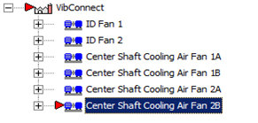
A customer with a need to monitor machinery remotely and limited to a small budget invested in the VIBCONNECT® RF system to keep their machines running. During a routine check of the data, it was noticed that a certain machine was in alarm. The OMNITREND® software easily identified the machine that was in alarm by the red indicator (see Fig. 1).
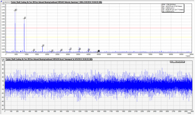
The customer contacted LUDECA to assist in analyzing the issue. The frequency did not match any of the components given for this machine. The waveform data showed extremely high levels of vibration and indicated that something was seriously wrong with this machine (see Fig. 2).
It was suggested that the machine be visually inspected for any abnormalities, including a strobe for the visual inspection. The strobe was locked into the known frequencies that were showing in alarm. The customer was able to identify that a broken belt was the cause of the high vibration levels (see Fig. 3).
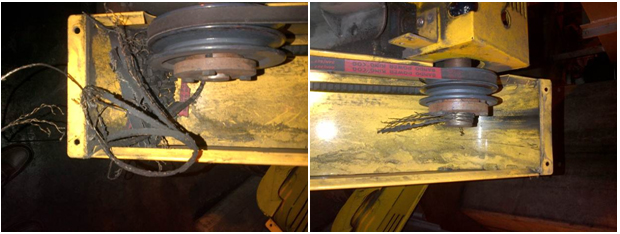
New belts were installed and the pulleys were properly aligned using the DotLine Laser pulley alignment tool to prevent future belt failures due to misaligned pulleys.
by Mickey Harp CRL
All machines and their components will exhibit wear at some point. This can lead to loss of function and require corrective action.
Wear particles are one of the most common sources of equipment reliability problems. They indicate that the oil is unfit and unreliable for operation in the equipment and will lead to damage to the equipment. These particles can give an insight into the type of equipment problems as well. The characteristics of wear are specific from machine to machine.
A facility in Texas lost key personnel in their condition monitoring program and experienced a gearbox failure. The plant was in need of a true online monitoring system for small and large particle quantities. They purchased the WEARSCANNER® oil particle distribution solution as a result. The WEARSCANNER solution not only counts and classifies but also has the ability to count low and high particle flow speeds which is of value to the customer.
The customer was able to adjust the different size classes in accordance with ISO 16232 and have the data fed directly into their control system.
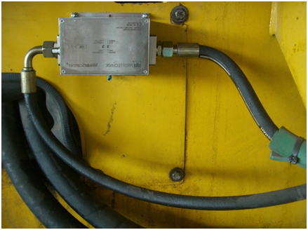
One of the keys to equipment reliability is keeping lubrication clean, cool, and free of moisture. This facility purchased the WEARSCANNER solution so they can actively monitor the cleanliness of critical equipment.
by Alex Nino CRL
Facilities apply different management strategies with condition monitoring spare equipment. Some facilities do not routinely operate spare equipment until the primary equipment has failed. Others operate primary and spare equipment for equal amounts of time. It is critical that the management scheme ensures that both primary and spare equipment are equally operational upon demand.
As a condition monitoring analyst, it is vital that you periodically analyze the condition of both the primary and spare machines. This will most likely require asking an operator to start both machines so a conditional assessment can be made. Management should ensure that both machines are made available to the reliability team as may be required and verify that conditional assessments are routinely completed on both.
What happens if the primary equipment becomes non-operational for some reason and the spare equipment has an unknown defect that prevents its operation as well? The outcome is not usually positive! It is important to maintain the reliability of both primary and spare equipment. Collecting periodic condition monitoring data on both will help ensure availability when required.
by Trent Phillips CRL CMRP - Novelis
Certain technologies have been used for a very long time to identify corrective actions required to keep equipment operational and reliable. Vibration analysis, ultrasonic monitoring, infrared thermography, motor condition evaluation, and lubrication analysis are examples of these technologies. Many terms have been used to describe their usage within a facility. One term often used is “Predictive Maintenance”. Unfortunately, this term can be used in the literal sense with dire consequences.
Many facilities mix all of the required ingredients together to create a successful maintenance and reliability program. Regrettably, many others fail in their efforts. Two of the primary elements for success are predictive maintenance and work execution. The predictive maintenance effort may be quite effective at identifying conditional changes in equipment that should be addressed before functional failures occur. Those efforts will not be fruitful if the results are not executed. The predictive maintenance team has to generate work that is planned, scheduled, and executed. If the results of their efforts are not executed, then the facility will plainly predict costly failures that will be experienced by the facility. Basically, the effort will shift from “Predictive Maintenance” to “Predictive Failures”.
Make sure your facility is not predicting failures. Make certain the results of the predictive maintenance technologies are executed before conditional changes result in equipment failures.
by Trent Phillips CRL CMRP - Novelis
What seems like a “great idea” at the moment can often lead to regret and unwanted consequences later. This is true when it comes to equipment reliability and condition monitoring. What “great ideas” can a facility have today that can lead to unwanted reliability consequences later? Unfortunately, the choices are many!
Determination of condition monitoring intervals can be one of those “great ideas” that is regretted later.
It is possible to apply condition monitoring more often than is actually required to detect conditional changes in equipment, resulting in extra expenses being incurred. Conversely, it is possible to monitor equipment too infrequently for important conditional changes to be noticed on time and failures to occur. It can seem like a great idea to base condition monitoring frequencies upon arbitrary intervals, available manpower, or some standard sampling frequency (such as 30, 60, 90, or 180 days.) Each of these could prove to be an unfortunate decision taken on behalf of your reliability efforts. Make sure your condition monitoring frequencies are based upon the P-F interval. The equipment will usually let you know how often condition monitoring technologies should be applied and the P-F interval is a measurement of that. The appropriate sampling frequency can be determined with some effort and will ensure that you have no reliability regrets later.
Also read our blog called: “How do you set your condition monitoring intervals?“
by Trent Phillips CRL CMRP - Novelis
Attendance at professional conferences can be expensive and remove the employee from the workforce for several days. So why allow your employees to attend a professional conference?
- The employee is allowed to network with others performing the same job functions. This allows sharing of knowledge and experiences that can be used to make improvements in your company.
- The employee will experience new tools, technologies, processes, ideas, and standards that can be used for improvements within your company.
- The employee can demonstrate their knowledge by doing presentations, participating in subject matter forums, etc., enhancing the reputation of your company.
- The employee can generate awareness about your company and its products.
- The employee will return with valuable knowledge that can be shared with other employees within your company.
You are cordially invited to visit our booth at these conferences where we will be exhibiting our shaft alignment, pulley alignment, vibration analysis, and balancing products.
by Yolanda Lopez
Are you running out of time to get your job done? Has your boss or supervisor saddled you with extra responsibilities? Are you not performing your PM tasks on time due to these extra responsibilities? If you answered yes to any of these, don’t feel alone in this ever-changing industry. We are all being asked to perform more with fewer tools and time. And yes, we must keep our equipment up and running!
I recently ran into this problem at a water treatment facility in the Caribbean. Besides the overwhelming amount of work demanded of the maintenance staff, they also have been unable to maintain their equipment. The plant was going longer than four months without any vibration analysis data collection on their machinery, resulting in preventable equipment failures with the consequently lost revenue and high cost of replacement. Due to the working environment, culture, and qualified staff shortage, the engineering group decided to invest in a wireless vibration monitoring system for their highly critical machinery.
After careful evaluation, they decided to install 8 VIBCONNECT RF sensors on four of their high-pressure pump sets. These pumps are critical in processing seawater into freshwater. Although the process of a desalination plant has several stages, the plant decided to first outfit these (four) 550 HP motors first before proceeding with the rest of the facility.
These critical pump motor sets cannot be ignored and have a good reliability program in place. Nor can they be ignored without end-user (consumer) dissatisfaction from no clean water availability due to equipment reliability issues. The plant made a small investment in the monitoring system in comparison to the cost of replacing the motors which failed.
As the maintenance manager stated:
If we could have prevented that failure and/or known that the asset was headed in that direction, we could have saved thousands of dollars. Not to mention the embarrassment of the bad press that comes from working in a government run institution…”
by Alex Nino CRL
A lot of facilities assign condition monitoring intervals based upon arbitrary schedules such as 30, 90, 180 or 365 days. Often, this is due to a lack of understanding of how equipment fails, misunderstanding of how conditional tasks such as vibration analysis work, available labor, and lack of importance placed upon condition monitoring efforts. These arbitrary collection intervals can actually lead to failures that go undetected and a loss of value from the effort.
To appropriately determine monitoring intervals, a couple of things should be known. First, the point in time (P) that the potential failure becomes detectable must be known (detected with vibration monitoring, for instance.) Second, the time (F) at which the potential failure would degrade to a functional failure must be known. This difference in time (P-F Interval) is the window to take corrective action and avoid the negative consequences of the failure. This difference in time will determine how often conditional tasks such as vibration monitoring must be done to detect potential failures from such things as bearing issues, etc. Typically, the monitoring interval would be set to half of the P-F interval. This allows enough time for the technology to detect the problem and for corrective action to be taken. However, in certain circumstances, it may be necessary to collect data at shorter intervals than half of the P-F interval.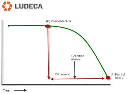
It is important not to assign monitoring intervals based upon gut feelings, arbitrary calendar intervals, and so forth. Let the equipment tell you how often monitoring must be completed. Not understanding the process above can lead to costly results!
by Trent Phillips CRL CMRP - Novelis
The following blog relates to those who field balance using a photo or laser tach and reflective tape.
By far the most common pitfall to field balancing is a problematic tach signal. When one balances a rotor using one’s field balancing unit (VIBXPERT® II, VIBXPERT, or VIBSCANNER®) the equipment is recording the energy displayed at the frequency of the signal from the tachometer. To help visualize the importance of a clear tachometer signal that is exactly 1 pulse per revolution, look at figure 1.
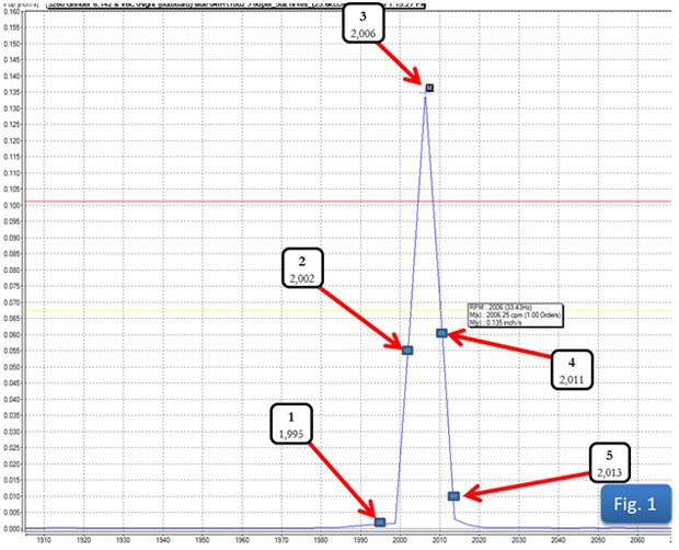
What amplitude will your equipment record if the tach pulses:
1. 1,195 times per minute?
2. 2,002 times per minute?
3. 2,006 times per minute?
4. 2,011 times per minute?
5. 2,013 times per minute?
We often start a balance job by haphazardly placing our tach and tape. Because both the tach and tape are well-engineered, we may go on without a problem. But just a little attention to some of the common tach signal problems is usually all it takes to avoid having to restart a botched attempt at field balancing. What should be avoided when setting up a tachometer?
1. Don’t place your tach too close to the rotor. Most tachometers are used in the fieldwork sending some type of light out and bouncing it back, so they have a sending function and a receiving function. The wavelength of the light is such that not just any light will be accepted by the receiver, but only that wavelength of light sent out by the sending unit. So the receiver counts a pulse every time that wavelength of light appears (or disappears, depending on whether you are triggering by leading or trailing edge). The receiver is no smarter than that, we must supply the rest of the intelligence. When we put the receiver too close to the rotor, even a poor reflector may be able to bounce back enough of the light signal to create a pulse. The balancing technician should determine the distance from the rotor to set up their tach with the understanding that they want a good signal bounced back from their chosen reflector AND ONLY THEIR CHOSEN REFLECTOR! Most often, a 6-inch space is sufficient.
2. Don’t place your tach pointing perpendicular to the rotor. Earlier we stated that “both the tach and tape are well-engineered”. One thing most of us field balancers take for granted is the reflective tape. This tape is actually a well-engineered tool. Reflective tape is faceted in such a way that light can strike it at an acute angle, and still be reflected right back along the axis from which it came. This allows the tach to be staged at such an angle that light will strike the rotor, even a rotor that is itself a good reflector, and be reflected off and away from the receiver UNTIL the tape comes into the line of the light, and then with its special faceting, it will bounce the light back to the receiver. This gives one clean pulse every time the tape comes around, and only when the tape comes around.
3. Don’t use old reflective tape that may not be in proper working condition. Make sure the tape is clean and in good shape. Reflective tape works very well when it is clean and in like-new condition, but can get dirty or even deteriorate if conditions are right. Replacing a small piece of tape is most often very quick, easy, and cheap compared to extra balancing runs or possibly even worse.
4. Don’t use a tach with dirty lenses. Make sure the tach lenses are clean and in good shape. When your lens is dirty, it forces you to do things (in order to get a strong enough signal to go through the dirty lens) that aren’t conducive to a clean, clear, once per revolution pulse; like move the tach too close to the rotor, or place it at a 90° angle to the rotor.
Doing everything we have suggested here could take all of 5 minutes (if you work slowly) at the beginning of a field balance job, but it could save a lot!
by Mike Fitch CRL
Recently, while assisting a customer in setting up a vibration database, the subject of creating the best trending template for a boiler feed water gearbox came up. This particular application requires trending templates to monitor a complex machine train consisting of four separate machines. For the purpose of this discussion, we’ll concentrate only on the gearbox in the machine train. The gearbox is a speed increaser. It is a little unusual in that a hydraulic torque converter allows the speed of the main boiler feedwater pump to be varied. This gearbox is designed with three individual shafts (an input shaft, intermediate shaft and output shaft), all enclosed within a single gearbox housing.
The speed of the input shaft is constant at 29.93 Hz (1796 rpm) and attached to this input shaft is a pinion gear with 88 teeth. The pinion gear runs in mesh with another gear mounted on the intermediate shaft with 27 teeth. This results in a gear mesh frequency of 2,633.84 Hz. We must determine the required frequency range (Fmax) by multiplying our calculated gear mesh frequency by 3.25 resulting in a Fmax of 8559.98 Hz. In the software, we can’t select 8559 Hz so we’ll need to select the next higher value, 10kHz.
The next step in the process is to determine the speed of the intermediate shaft by using the following formula:
Intermediate shaft speed = 29.93 Hz × 88 teeth = 2,633.84 Hz / 27 teeth = 97.54 Hz or 5,852.4 rpm.
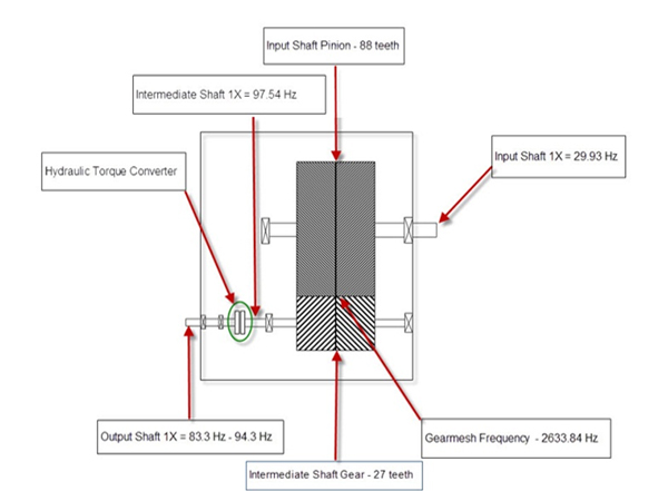
We must now determine the required lines of resolution (LOR) since we have two fairly closely spaced running speeds. We have the intermediate shaft speed, running at a constant speed of 97.54 Hz and the output shaft speed which is variable.
When the boiler feedwater pump is operated at 100% the output shaft running speed of the gearbox is 94.33 Hz or 5660 rpm. There are only 3.21 Hz or 192.6 CPM between the two shaft speeds within the gearbox. Therefore, our lines of resolution setting will need to be high enough to provide separation while performing analysis. With a Fmax setting of 10kHz, we will need a minimum of 3200 lines of resolution to distinguish between the two shaft speeds. 10kHz Fmax / 3200 LOR = 3.125 Hz bin width, but to be on the safe side I would recommend selecting the next higher resolution setting (6400 LOR). This will provide a 1.56 Hz (96.3 CPM) resolution to easily see the two different shaft running speeds for accurate analysis.
Below is an example of improper resolution for accurate analysis:
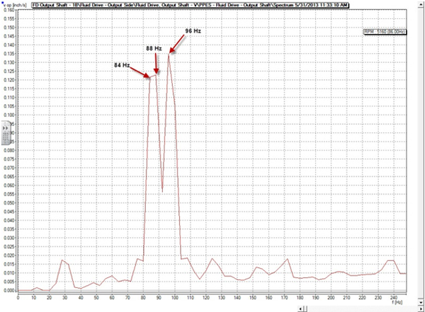
Improper resolution settings resulting in a flat top 1× for the output shaft speed. Proper resolution settings: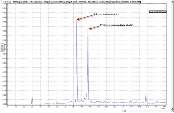
Correct resolution settings allowing clear distinction of the output shaft speed.
The lesson here is that proper vibration analysis requires understanding the machine design. Additionally, it is critical that the proper maximum frequency (Fmax) and lines of resolution (LOR) be determined. Improper Fmax settings will result in data being missed. Inadequate lines of resolution (LOR) can cause closely spaced peaks to merge together making it impossible to distinguish between them. These errors will result in poor vibration analysis results. Pay close attention to the details when setting up the equipment in your vibration database.
by Dave Leach CRL CMRT CMRP
Purchasing a condition monitoring tool is one step in your journey to implementing a reliability program. Proper training on how to use the new technology, planning the work correctly, ensuring the work is completed on schedule and done so correctly is critical to success. Just as important is understanding the risks associated with your equipment, especially when it fails. A criticality assessment along with failure modes and effects analysis will help you understand those risks and determine where to focus your maintenance activities.
I recently spoke to a plant engineer that had purchased alignment equipment and vibration equipment from LUDECA. He had performed several alignments and collected baseline vibration data. The decision was made to start aligning machines that required maintenance and this was a wise choice to ensure failure modes were not inserted into equipment during routine maintenance activities. Unfortunately, this facility had not performed a criticality assessment on their machinery! It turns out that the plant had a catastrophic failure on a piece of equipment that was vital to the overall production processes of the plant. The first comment made was “why did we have this failure when we recently invested in alignment and vibration equipment?”
You must fully understand the risks to safety, production, environment, and profits that your equipment imposes on your facility. As you can see from the example above, not understanding these factors may lead to continued equipment failures and their undesired consequences. To ensure that you do not continue to experience maintenance failures requires that you fully comprehend the risks that each piece of equipment entails. Had this facility understood the failure modes and the (criticality/risk) impact each machine posed, they would have been able to focus their maintenance efforts where they were most needed to keep the plant efficiently operational.
As part of this endeavor, it is important to apply condition monitoring (vibration analysis and properly targeted alignment, among other things) on the equipment within your plant, because it is extremely difficult to be reliable without doing so. However, you must understand how and where to direct those efforts to ensure that unwanted risks are reduced. Understanding how your equipment can fail (FMEA), the consequences of those failures (RCM or risk assessment), and what equipment is most important to keep your plant operational (criticality assessment) are all important to ensure that your maintenance efforts are properly focused. These efforts may avoid the experience this facility had and prevent your plant from experiencing the same unwanted effects.
by Frank Seidenthal CRL