As Published by COMPRESSORtech2 Magazine October 2016 issue
by Karl Hoffower – Condition Monitoring and Reliability Expert for Failure Prevention Associates
Combining ultrasound and vibration sensing adds precision to recip valve analyses
Over the past decade, ultrasonic condition monitoring of reciprocal compressor valves has become more widely known. However, it does not seem to be widely used.
Ultrasonic testing measures high-frequency sound waves, well above the range of human hearing.
These ultrasound devices record the high-frequency signals for analysis later. Trending valve cap temperatures is the most common condition monitoring technique for monitoring
compressor valve health.
Ultrasonic testing of compressor valves and vibration monitoring of rotating components is an informative, preventative-maintenance practice. Compressor valve deficiencies with opening, closing, or leaking may be diagnosed using the ultrasound recording functions.
Steven Schultheis, a Shell Oil Co. engineer, addressed the issue in a paper presented at the 36th Turbomachinery Symposium in Houston in 2007.
“Trending valve temperatures have proven to be valuable in identifying individual valve problems, but are most effective if the measurement is made in a thermowell in the valve cover.” Schultheis wrote. “Ultrasound has proven to be the preferred approach to the analysis of valve condition.”
Failure Prevention Associates completed an experiment with a major midstream gas transmission company to see if this type of condition monitoring tool can effectively find fault conditions well before another technology is used.
Ultrasound meters (such as the SDT270 from SDT Ultrasound Solutions) have digital readouts that indicate the level of ultrasound detected. These devices have been used for decades to “hear” air, gas, and vacuum leaks. The intensity or amplitude of the signal is expressed in decibels — microvolts. (dB[A] μV). The dB(A) is a common intensity unit for sound intensity; μV designates the engineering reference unit being used with a piezoelectric sensor.
Converting an airborne ultrasound detector with a contact sensor allows a technician to monitor what is happening inside a machine, whether it is a bearing, steam trap, or valve.
Ultrasound detectors are designed to operate in a specific and narrow frequency band. Then through the “heterodyning” step high frequency sounds down into an audible format that the technician can hear through headphones. During the heterodyning process, the quality and characteristics of the original ultrasound signal are preserved.
Read full article complementary-condition-monitoring-boosts-reliability-article
by Yolanda Lopez
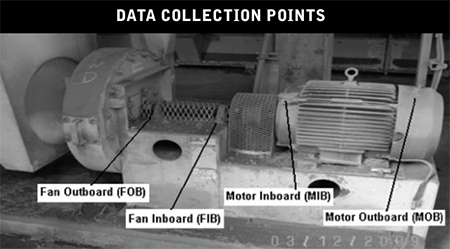 To facilitate the initial learning curve, a labeling system was implemented to help technicians collecting data identify bearings that were part of the initial survey. These descriptors were laminated to prolong their life in the unfriendly environment of a typical cement plant. Standard locations for data collection needed to be understood since labels would become difficult or impossible to read over time.
On-the-job training included an understanding that readings collected on the drive motor bearings needed to be collected from the grease fitting on the non-drive end and from the upper portion of the end bell housing on the drive end. On driven equipment bearings, where direct access was possible, the ultrasound readings were to be taken in the horizontal plane directly from the bearing housing. (Note: with ultrasound, it is not necessary to record data from multiple planes on the same bearing). Technicians were trained to take ultrasound readings as close to the bearing as physically possible while respecting personal safety.
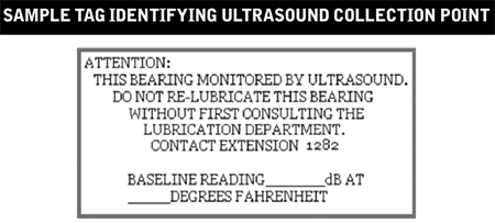
This simple label proved important to the integrity of the pilot project to prevent greasing from well-intentioned lubricators.
by Allan Rienstra - SDT Ultrasound Solutions

LUDECA is proud to announce that effective October 14, 2016, LUDECA is certified as an authorized SDT Service and Repair Center for the United States.
Our factory-trained technicians are highly experienced and committed to providing our customers with excellent service.
We look forward to servicing your SDT ultrasound products at our Doral, Florida location.
For more information, visit our website.
by Ana Maria Delgado, CRL
Compressed air represents one of the highest utility costs in industrial plants. It’s also one of the most misunderstood; which explains why leaks account for, on average, as much as 35-40% of total demand.
Leaks are often considered an unavoidable cost of business. Many of us simply don’t realize the high cost of compressed air leaks.
Add to that the fact that:
- Leaks don’t present a visible threat to safety
- Leaks don’t make a mess on the floor
- They are invisible
- We can’t hear them over the other noise in the plant
- We don’t need permission to open a 1/4” air line and waste thousands of dollars per year
Remove our misconceptions about the high costs of leaks and we create a huge opportunity to save money, increase environmental sustainability, and drove positive culture change.
Download the Leak Surveyors Handbook to learn more.
by Allan Rienstra - SDT Ultrasound Solutions
Ultrasound is an essential part of a proactive reliability program as it can reduce or eliminate wasted compressed air through leak detection and repair. This Infographic outlines an effective way to survey your systems and detect leaks and brings you one step closer to best practices for your ultrasound program.

Download Infographic
by Ana Maria Delgado, CRL
Like any job, there is a right way and a wrong way to do things. Simply listening to a bearing with an ultrasound device that gives no quantitative feedback is a recipe for disaster. The audible feedback is too subjective to draw any comparative conclusions. No two people hear the same and there is no way to remember what the bearing sounded like a month ago.
The third mistake is depending solely on subjective ultrasound data when precise quantifiable data is available.
Always use an ultrasound instrument with digital decibel metering. Better still, use a device that provides multiple condition indicators. Max and Peak RMS decibel measurements indicate alarm levels and greasing intervals while Ultrasonic Crest Factor provides insight about the bearing condition in relation to its lubricant. Crest factors help us differentiate between bearings that need grease and bearings that need to be replaced.
Download the Ultrasound Lubrication Technician Handbook
by Allan Rienstra - SDT Ultrasound Solutions
The second mistake we should all avoid is adding too much, or not enough grease. Too much grease builds up pressure pushing the rolling elements through the fluid film and against the outer race. Increased friction and temperature dramatically shorten the bearing’s life. Not enough grease will have the same life-shortening effect.
How do we know when just the right amount of grease has been added? Ultrasound of course. Listen to the bearing and measure the drop in friction as the grease fills the bearing cavity. As the decibel level approaches normal baselines and stabilizes carefully slow the application of lubricant. Should the decibel level begin to increase slightly, STOP! The job is done.
Download the Ultrasound Lubrication Technician Handbook
by Allan Rienstra - SDT Ultrasound Solutions
Lubricating a bearing once per week or once a month may seem like a sensible thing to do. After all, performing scheduled maintenance at regular periods is an age-old concept ingrained in each of us early on. Even OEMs still advise best practices based on time intervals to ensure maximum asset lifespan.
The problem with any blanket solution is that they ignore the effects of variables.
Two motors may be the same out of the box but end up in entirely different situations. While one lands in a hot and humid climate, another could be installed in a cold and arid climate. One may be used in a high-speed low load application while another at low speeds but with frequent starts and stops.
It is irrational to expect the maintenance needs of one to be the same for another when the conditions they operate in are so different.
Bearings need grease for one reason only; to reduce friction. As long as the lubricant is performing that service well, there should be no need to change it. Yet we frequently do, with catastrophic results.
Re-lubricating a bearing just because your calendar told you “time’s up!” is the first mistake. Monitor ultrasound friction and know when it’s the right time to grease.
Download the Ultrasound Lubrication Technician Handbook
by Allan Rienstra - SDT Ultrasound Solutions
Bearings are widely used in industrial applications and are considered a crucial component. Bearing failures, when not detected in time, are responsible for the unscheduled shutdown and expensive downtime. They may even lead to catastrophic breakdowns.
Slow speed-bearing monitoring is a different story. When speaking about rotation speeds of less than 250 rpm the “normal” technologies, such as vibration or thermography, are usually blind to problems until it is too late. In slow speed bearing applications, early failure detection remains a notorious problem … for those who do not use ultrasound.
Monitoring the condition of slow speed bearings with ultrasound can reveal pitting, impacting, rubbing, and other mechanical defects well in advance of the failure stage. Dynamic data is best analyzed in the time domain but it is important that a long enough time sample be captured. The golden rule is to capture 3 to 4 revolutions of the bearing.
So deciding how long is long enough is a matter of multiplying the number of shaft rotations (4) by the period (p). The period is the reciprocal of frequency or:
p = 1?f
If you want to capture 4 rotations on a 15RPM bearing, therefore:
p = 1?0.25 * 4 = 16 seconds of data
To make data collection easy, the acquisition time parameter can be set up as part of your survey. So when you are creating your database in Ultranalysis Suite Software (UAS) simply enter 16 seconds.
by Allan Rienstra - SDT Ultrasound Solutions
July 2016 – Flow Control Magazine
Maintaining the health of the assets that make up a steam system brings benefits that are measured by cost reduction, improved product quality, and decreased risk to safety. When employees undertake a project that delivers on goals like these, a fourth win is returned by default — improved reliability culture.
When steam system health is ignored, components degrade and efficiency erodes. Over time the system reaches a point where it is no longer able to deliver on its engineered purpose. The maintenance manager’s phone rings. Production needs a fix, and they need it fast. Now it is time to fight fires again.
Which scenario does an organization pursue? Should it pursue the reactive one or the calm, planned approach that sees problems before they emerge, reaps the benefits of cumulative cost savings, has impeccable safety records, and culture of motivated and artistic employees eager to change their world?
Read the full article: Creating reliable steam systems with ultrasound to better understand the importance of monitoring the condition of a steam system to then act upon the data.
by Allan Rienstra - SDT Ultrasound Solutions
Today’s more evolved ultrasound data collectors present results that take reliability practitioners beyond the single decibel. Using only an overall dB value may indicate something inside the machine has changed since the last readings were taken. But it provides no additional insight to determine what type of defect may be present.
Moreover, a single dB only provides a useful trend if the inspector has control of the acquisition time during data collection. Acquisition time needs to be adjusted in concert with the speed of the machine. More time for low-speed applications and less for high. The aim should be to capture a minimum of 2-3 full shaft rotations.
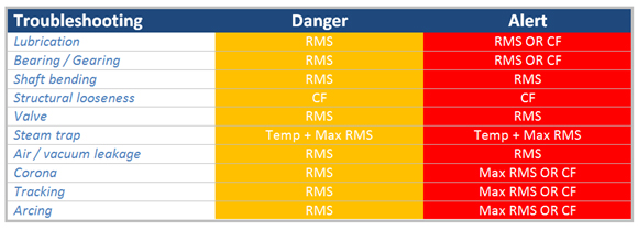
The SDT270 takes inspectors beyond the single decibel by presenting ultrasound data in terms of machine condition. We call them Condition Indicators and there are four (RMS, Max RMS, Peak, and Crest Factor (CF)) and are abbreviated as 4CI. Ultrasound identifies defects in machines when those defects produce one or more of the following phenomena: FRICTION, IMPACTING, or TURBULENCE (FIT).
Some examples:
- A bearing that requires lubrication will present higher levels of friction. Therefore, an RMS danger alarm will be triggered at 8 dB and an RMS/CF alarm when severity increases.
- A bent shaft produces higher levels of friction and therefore presents danger and alert warnings with the RMS condition indicator.
- Electrical defects such as arcing, tracking, and corona are first alarmed with the RMS condition indicator and severely alarmed with Max RMS and CF.
- A faulty steam trap is detected with an elevation in Temperature and Max RMS.
Traditional ultrasound is useful for trending decibel levels that alert us when machine condition changes. Evolved ultrasound goes beyond the single decibel to recruit Condition Indicators that help inspectors determine the type of defect that is creating the alarm. SDT’s Four Condition Indicators demonstrate how ultrasound must be used for both defect alarm and identification.
by Allan Rienstra - SDT Ultrasound Solutions
Going “green” and saving energy are two separate ideals that merge by circumstance, and focus on a campaign with huge potential wins. This battle starts in the air compressor room (supply-side) and branches throughout the facility (distribution) to wherever air is needed (demand side). Along the way there are leaks, wasted dollars spent and energy consumed, all the while enlarging your carbon footprint. Take a look at these compelling reasons to tighten your compressed air system:
- Compressed air production is the 2nd or 3rd highest source of energy consumption in most companies.
- On average, air compressors account for 18% of all industrial electricity consumption in European manufacturing plants. Some suggest that compressed air costs account for as much as 30% of a manufacturing plant’s electricity bill.
- For every kWh spent on compressed air, an additional 0.8 kg of CO2 per month is spewed into our atmosphere.
- 75% of the total cost of your compressed air system goes to your electricity provider. The other 25% is accounted for by capital costs and ongoing maintenance.
- On average, only 43% of compressed air produced gets used to satisfy real demand.
- On average, 34% of compressed air produced is wasted by leaks.
- The remainder is consumed by wasteful applications and artificial demand.

by Allan Rienstra - SDT Ultrasound Solutions
Reposted from RELIABILITYWEB®
- Assemble a team and identify applications for a program
- Justify needs by recognizing key areas where improvement can be benchmarked
- Set written goals for the program
- Establish how ROI will be measured
- Purchase quality ultrasonic inspection equipment
- Invest in certification training at both management and user levels
- Choose a leader to technically carry the program forward
- Establish a system to reward the successes
- Frequently review the progress as part of regular meetings
- Ensure everyone involved is 100% mentally invested in the program’s success
Tip from Hear More: A Guide to Using Ultrasound for Leak Detection and Condition Monitoring by Thomas J. Murphy and Allan R. Rienstra.
To learn more about airborne ultrasound, download a chapter preview of Hear More.
by Allan Rienstra - SDT Ultrasound Solutions
Friction is all around us. Without it, we would have difficulty walking, running, or even standing. We need friction to drive our cars and fly our airplanes, and we need friction for our motors to drive pumps and our pumps to push product. So when it comes to our plant assets, friction is both friend and foe.
Lubrication of rolling element bearings is one of the most misunderstood tasks in the industry. Can it be true that 40% of bearings never live to their engineered life cycle and bad lubrication practices are a leading cause?
To achieve optimal lubrication we must know:
- When a bearing needs new grease
- What quantity of new grease is required
- And how much is TOO MUCH!
Acoustic Lubrication with ultrasound testing is the technology of choice for Lube-Techs who want to avoid these three common mistakes:
Three Mistakes to Avoid When Lubricating Bearings:
- Lubricating based on TIME instead of CONDITION
- Over or under lubricating the bearing
- Using low quality “Listen-only” ultrasound instruments
To Hear More about implementing a world-class ultrasound greasing program, download Ultrasound Lube Technician Handbook.
by Allan Rienstra - SDT Ultrasound Solutions
As Published by BIC Magazine December 2015 issue
A world-class reliability program is not achieved overnight, yet you must start somewhere. Your first step is to vest your entire human capital in its success. Reliability is a culture, not a goal, and it flows from the top down.
Therefore, executive sponsorship with integrity and enforcement is a must. Obtain buy-in to the culture of reliability from everybody in your organization, or the effort is doomed to fail. Start with this realization, and your reliability effort will ultimately succeed, and you and your stakeholders will reap its rewards.
The reliability workflow must be well organized and underpinned by a Computerized Maintenance Management System (CMMS). Let’s look at how it works in a world-class program.
Ultrasound analysis detects a bearing fault in a critical motor early in the P-F curve. The analyst enters this data in the CMMS and trends it. The analyst decides to request a work order with recommendations. This is Stage 1 in the work order process.
The work order is now reviewed by both maintenance and operations, thereby ensuring buy-in from operations as well. This is Stage 2. This review process ensures only truly needed or valuable work is approved. Also, older open work orders can be combined with this one to further streamline planned activity on the asset. For instance, an earlier work order was created to align the machine, but the work was never carried out, resulting in the bearing damage the ultrasound analyst has now detected. The review process would catch the older open order and add it to the present order. This would prevent the millwright from going out to align the machine tomorrow only to have a repair technician go out the following week and repair the motor but do no alignment on it. This review process tries to eliminate inefficiency, duplication, and detrimental work sequences.
Stage 3 assigns the work order to the maintenance planner for action. Only approved and truly necessary work enters the planner’s backlog. The planner ensures work is properly prioritized. Two things are needed: The criticality ranking of the asset (ascertained from systems’ criticality analysis) and its operational criticality. Both of these factors can be multiplied together to create a more accurate prioritization of the workflow. The planner creates a new work plan if needed and should consult with maintenance supervisors and technicians; valuable insights may be gained into what parts, tools, and equipment should be specified in the work plan. Next, the planner orders the maintenance, repair and operating materials (MRO) spares, and tooling required to complete the job and verifies the parts are available and kitted (best practice). The planner should not concern himself with scheduling.
Now on to Stage 4: assignment to the scheduler. The scheduler allocates the HR and necessary time to accomplish the task, with a cushion for unforeseen complications. He too should consult with the maintenance supervisor and technicians to obtain cooperation and buy-in to the schedule. Coordination with operations is crucial. Operations “owns” the equipment and must sign off on the schedule to bring the asset down.
Stage 5 assigns the order to the appropriate maintenance and electrical supervisors, who in turn assign specific tasks in the work plan to their respective repair technicians, electricians, and millwrights, and verify MRO spares has delivered the parts kit to the proper location.
Now the work order enters Stage 6: the work execution phase. Once the technicians have completed the work, they report to their supervisors, who return the asset to active duty status in the system. Operations is notified the asset is ready for service, and MRO spares is notified of any unused parts and supplies that should be returned and reintegrated into the MRO spares inventory. Technicians and supervisors should feed their observations and data into the CMMS system.
Stage 7 sees the ultrasound analyst performing follow-up data collection on the asset to ensure all is well. The work now goes back to the planner to be formally closed. This ensures all important data has been accumulated and distributed within the system, enabling key performance indicators to be updated.
As good data accumulates, reliability engineering will use it to improve the entire reliability and maintenance process, discover frequent failure patterns, identify training needs, drive out defects, streamline production and help to improve the design process. As the plant becomes more efficient and productive, greater resources can be allocated to defect elimination and strengthening condition-based maintenance technologies, further impelling the transition to a proactive, reliability-centered culture. Reliability is a never-ending journey of continuous improvement.
by Alan Luedeking CRL CMRP
Combine vibration monitoring and ultrasound for more cost-effective predictive maintenance
The best overall machinery monitoring program is one that utilizes multiple, integrated monitoring technologies.
In brief:
- The best overall machinery monitoring program is one that utilizes multiple, integrated monitoring technologies that are well-suited to detect expected failure modes.
- One goal of PdM is to determine how much time is left before a machine will fail, so plans can be made to minimize downtime and damage while still getting the most useful life from the machine.
- An application where ultrasound and vibration work well together is a mechanical inspection.
Reliability-centered maintenance programs are most effective and most profitable when a variety of appropriate technologies and tools are used to complement one another. Vibration analysis and ultrasound are as complementary as two sides of the same coin. Ultrasound is a useful monitoring tool, capable of detecting failing rolling element bearings and over-and under-lubrication conditions. The best overall machinery monitoring program is one that utilizes multiple, integrated monitoring technologies that are well-suited to detect expected failure modes. For low-risk machines, vibration analysis can be performed by a mechanic or operator using a vibration data collector or vibration meter. For machines of higher criticality, a certified vibration analyst should use advanced vibration data collection and analysis hardware and software.
Read my comments in this valuable PLANT SERVICES article.
by Trent Phillips
Ultrasound instruments listen for high-frequency sounds that are not heard in the range of normal human hearing. Typical applications include compressed air & gas leak detection, electrical inspection, and condition monitoring applications.
Ultrasound technology can easily be implemented into established maintenance & reliability programs that are currently using other technologies such as vibration analysis & infrared. The best M&R programs are ones that do not rely on one single technology but on multiple technologies. Here are some tips to assist you:
Best Practices for Mechanical Inspection
• Initial ultrasound data should include both decibel readings and sound files
• Once baseline has been established, decibel readings are recorded
• Set alarm levels
• Record both decibel readings and sound files when an alarm is reached
Best Practices for Electrical Inspection
• Infrared scans are typically done by an outside service provider annually, or semiannually. In between annual infrared scans, use ultrasound to periodically listen for conditions.
• Only relying on infrared increases the chances of missing conditions not detected by infrared
• The best method of diagnosing electrical issues with ultrasound is through the use of recorded ultrasounds
Thanks to Adrian Messer with UE Systems, Inc. for sharing these tips with us.
by Ana Maria Delgado, CRL