Many accidents can be avoided by simply following a company’s safety procedures. There are many things that might not be considered when thinking about safety. For example, keeping your workplace clean, and free of debris. If objects or spills are left around the work environment, anyone may trip or slip on them. Debris can also end up on or inside machinery and damage equipment. Knowledge of your surroundings can also keep the workplace safe. Know where the nearest fire extinguishers are, and where the emergency kill switch for your machinery is located, as well as emergency exits, and first-aid kits.
Improper attire can also be a safety hazard if not appropriate. Neckties are taboo and long hair should be picked up in a ponytail or tucked in your shirt. Loose long sleeves can get tangled with machinery. Protection of the eyes, ears, and head is imperative while in the factory environment.
In intrinsically safe (IS) environments, any electronic components that enter the area must be certified as IS. An item can be deemed as IS when its potential electrical and/or thermal energy is low enough that, within a hazardous atmosphere, ignition will not take place. Cell phones, digital cameras, and MP3 players are not intrinsically safe and can be hazardous in explosive atmospheres. If working in an intrinsically safe environment, follow your company’s safety guidelines for a better, safer workplace.
Awareness and communication are also important when it comes to safety. Warning your coworkers when they are violating safety procedures can avoid many accidents. It is good practice to advise those around when a machine is being turned on, or when hazardous materials have been exposed. Always obey all safety regulations. They are in place for our own benefit, not just the company’s.
by Adam Stredel CRL
When performing a Dynamic Balance procedure a few things should be considered:
1. Inspect the structure/mounts and ensure there are no cracks or loose bolts.
2. If driven via a belt drive make sure that the belt is in good condition and properly tensioned.
• Remember that the second harmonic of a belt frequency can be very close to the rotational speed of the drive.
3. Inspect the rotating element for the build-up and clean as necessary.
• Remember that even slight build-up (i.e., dust) can be the cause of an unbalance.
4. If the rotating element is a blower, count the number of blades.
• Frequently correction weights will have to be attached to the blades and therefore it may be best to use a fixed location method.
5. If the equipment is down when you arrive, replace the reflective tape or attach new tape as may be required.
• This will ensure accurate phase data.
6. When taking your initial phase data turn the averaging function off, if possible.
• Monitor the phase data for a brief time to ensure its stability. Doing this could identify potential problems.
7. Keep good documentation, keep written notes on what was found:
a. Phase and amplitude data
b. Number of blades
c. Correction locations
d. When weights were attached or removed
e. How much weight was attached or removed
f. Sensor placement
g. Tachometer placement.
8. If the equipment is variable speed such as VFD drive or DC drive ensure that the speed is repeatable to within 5% or less run to run.
by Gary James CRL
PERMALIGN® is the world’s leading machinery positional change measurement system. Since 1986, it has proven itself as the most accurate and dependable solution for thermal growth measurement. PERMALIGN is a laser-based system capable of detecting and accurately measuring both relative or absolute movement, depending on the prisms and setups selected. To this day, it remains unequaled in ease of use and precision of measurement.
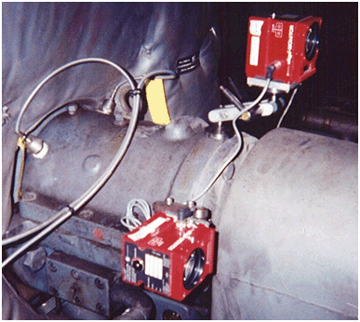
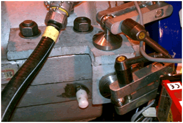
A great majority of the PERMALIGN applications involve installing two roof prisms and two laser monitors on the inboard bearing housing of each machine. By measuring the bearing housing movement, the alignment change can be determined from the relative movement of the machines. The preferred method of installation is to drill and tap a 10-32 × ½” deep hole into some part of the machine that is directly connected to the bearing housing as shown below.
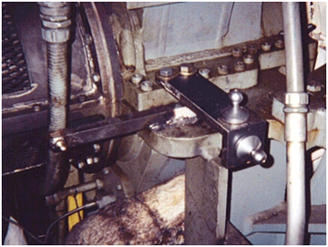
Sometimes, this is not possible. The next solution is to construct a strong bracket (usually of 5/8″ thick steel plate) that can be physically attached to the bearing housing. This usually involves temporarily replacing a housing bolt with a longer bolt that allows the bracket to be “sandwiched” to the machine as shown below.
Sometimes, the presence of obstructions (proximity probes, electrical conduit, piping) can interfere with the positioning of the brackets and the PERMALIGN components. When designing brackets for these situations, the fastest and easiest method is to take advantage of CAD. I am not referring to “Computer-Aided Design”, but something far more effective in the field – “Cardboard Aided Design”!
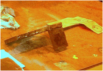
Get a piece of cardboard, and a pair of scissors, and cut out a template for the bracket that you will need. You can bend it in any shape you wish and mark your mounting points with a marker. Need to make a design change? Just cut it to change the dimension! As shown below, this precision-engineered template was crafted with a pocket knife.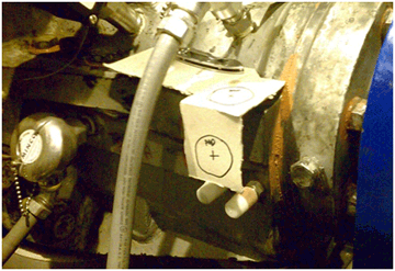
Below is the template next to the fabricated piece. The template provides an easy-to-follow map for building the bracket. PERMALIGN brackets are usually torch cut in the field, ground, and welded together. The design emphasis is for it to be STRONG, not pretty!
Below is the final result. The cardboard template allows the design to be checked prior to fabrication and installation.
by Daus Studenberg CRL
Many of you watch or at least are familiar with the various Crime Scene Investigation (CSI ) television series where advanced forensic techniques are utilized to catch the criminals or “bad actors”. When it comes to your “bad actors” from an equipment perspective, where is your CSI unit? What is your forensic approach to equipment failure?
Rather than simply accepting equipment failures, they should be literally treated like crimes against your organization. These failures rob the organization of equipment availability and capacity, divert your Maintenance resources, consume spare parts, and steal profit. While you may not be able to prevent failures from occurring, at a minimum you need to understand why they occurred from a root cause perspective.
To do this, perform an autopsy on the failed equipment. Cut apart failed bearings or open gearboxes as examples. Inspect the components. Ideally, the Maintenance Engineering group should become your CSI Unit and investigate to understand the root cause. In the event that the organization does not have the Maintenance Engineering function, you can develop a “champion” who is detail-oriented with strong mechanical skills. I don’t advocate rotating the champion function among many people as it takes time to develop the necessary skills.
Another resource for consideration is that many quality vendors provide a service of analyzing the failures so that you can both understand how the component failed, and often at no cost. In addition to vendors, there are a number of other resources available to you such as the Maintenance Engineering Handbook, and searching Google images on the Internet.
In the end, the goal is to understand the possible root cause(s) so that you can modify your practices to ensure the elimination of those potential failures from robbing your organization. If doing autopsies, what are some of the root causes and outcomes that your organization has identified? What other steps or ideas would you recommend regarding autopsies?
This was a guest post from Jeff Shiver, CMRP, CPMM of People and Processes, Inc.
by Ana Maria Delgado, CRL
Fault frequencies are very important in vibration analysis because they allow the analyst to correlate vibration data to specific components in the equipment that may be in some stage of failure (equipment faults). Fault frequencies change with any adjustment in the speed of the equipment being monitored. Most modern vibration data collectors and software will automatically re-calculate the displayed fault frequency information as the rotational speed of the equipment changes. Component information (bearing information, gear information, etc.) is required to calculate and display the fault frequencies of specific components in machinery.
It is important to create fault frequency setups at the beginning of a vibration analysis program. Not doing so will affect the overall success of the vibration analysis program.
by Ana Maria Delgado, CRL
When aligning a vertical flange-mounted machine, it can be helpful to tweak the flange configuration in your laser alignment system to take advantage of different shimming alternatives. For instance, if the OD of the flange is larger than the diameter of the mounting bolt circle, a good laser system will compensate for this by taking into consideration that when shimming your pivot point is not the bolt circle but the flange OD. Thus, all shimming corrections will be positive.
However, if you already have shims at all the bolt positions, you could take advantage of the opportunity to minimize the required shimming corrections by forcing the smallest correction position to be zero. Do this by entering a distance for flange OD as being equal to your bolt circle. Of course, the best laser systems already allow for all the different shimming alternatives (positive, negative, and zero-sum options) right in the software, so you don’t have to use this trick.
by Ana Maria Delgado, CRL
Knowing the exact bearing information for your equipment can make bearing defect analysis much easier.
However, it may not always be possible to acquire the bearing information for your equipment. This can make it difficult to determine the bearing fault frequencies for correct analysis.
It is possible to remember easy formulas to calculate the approximate bearing fault frequencies for rolling element bearings. The following formulas are easy to remember and can help you when the bearing information is not known:
FTF = 0.43 × RPM
BPFO = 0.43 × N × RPM
BPFI = 0.57 × N × RPM
Where:
FTF = Fundamental Train Frequency
RPM = Revolutions per minute
BPFO = Bearing Pass Frequency Outer Race
N = The number of rollers
BPFI = Bearing Pass Frequency Inner Race
The values derived from these formulas should be within 10% – 15% percent of the actual bearing fault frequencies.
Other formulas are available that will more accurately estimate bearing fault frequencies than the ones listed above. LUDECA will be happy to provide those to you upon request.
by Trent Phillips
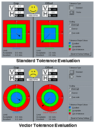
If you are aligning very critical machines and your laser system does not offer you the ability to apply vector tolerances, you can still do so manually, by keeping these criteria in mind:
The standard industry norms of 2 mils offset and 0.3 mils per inch of angularity at 1800 rpm equate roughly to vectors of 1.4 mils of offset and 0.17 mils per inch of angularity. Therefore, you can apply a sliding scale when you look at your misalignment results: If you have misalignment only in one plane (either vertical or horizontal), apply the full value of the standard tolerance; if you have a roughly equal misalignment in both planes apply the more conservative values shown above to both. This way you will not exceed your vector limits in any direction.
To find the vector limits for any RPM, simply take the square root of the standard limits.
Of course, none of this would be necessary if you have one of the better laser systems that feature vector tolerances and calculates them for you automatically.
by Alan Luedeking CRL CMRP
Your vibration software should have the capability to automatically import and export data from and to your CMMS system. Vibration programs like the OMNITREND® software can provide you with the means to address this issue.
Having the ability to automatically share information between your CMMS system and vibration software can be of great value. This capability can allow you to automatically build your vibration database with the same equipment names, equipment IDs, and hierarchy locations that are contained in your CMMS system. This can potentially save your company critical time and expense when starting a new vibration program or updating your current program.
Alarm condition information and much more can easily be shared between your CMMS software and vibration software. This provides the ability to alert your Maintenance Manager, planning and scheduling resources, and other team players about the important equipment conditions found by your vibration program.
Most CMMS and vibration software do not directly share information. Direct storage of data into another program greatly increases the risk of information corruption. Of course, this is never a good thing when it occurs and the risk should be minimized as much as possible. Most CMMS and vibration programs have the ability to map specific information for import and export via a file transfer process. A template is created that determines what information should be exported and in what format it should be stored. The template is stored and automatically executed on a scheduled basis determined by the user. Both the CMMS system and vibration software will create temporary files to share the required information with each other. Each system will automatically import this information and store it in their specific databases(s) from the temporary files. This type of process minimizes your efforts and provides routine and scheduled data sharing between both systems.
This type of data exchange will provide continuity in your reliability efforts and removes confusion when creating work orders based on the defect findings from your vibration program. The result will better integrate your reliability program with your maintenance process.
by Ana Maria Delgado, CRL
Measuring machinery misalignment with today’s tools, particularly computerized laser alignment systems, and well-designed bracketing is no longer as difficult a task as it once was when all you had were a straight edge, feeler gauges, and maybe a set of dial indicators with some make-shift hardware.
Why then, is it that aligning the machinery to given target values is so often still so cumbersome and time-consuming? There may be several reasons, among them unnecessarily tight tolerances specified by the machinery vendor, problems with worn-out bearings, inadequate bases, lack of jackscrews, etc. But by far the greatest obstacle to expeditiously reaching your alignment goal is soft foot. ‘Soft foot’, or machine frame distortion can be measured by various means, and indeed it must be measured and corrected before proceeding with the alignment. Why? Simply because an uncorrected soft foot condition will make alignment a trial-and-error procedure where indicated corrective shimming and lateral moves no longer bring you to the expected results.
Severe soft foot may also be quite harmful to the machinery itself.

Correcting soft foot may not be easy, but it is worth every minute you spend on it because once done, the alignment of the machines becomes a much easier task. Many alignment systems available today have soft foot measuring programs, and the most advanced system even features a soft foot ‘wizard’ which analyzes the type of soft foot measured (there are a number of different soft foot conditions) and suggests how to correct it.
Conclusion: If you want to make aligning your machinery easier, quicker, and more accurate, start by correcting soft foot.
Read: Types of Soft Foot
by Ana Maria Delgado, CRL
One of the problems we can encounter while performing an alignment is the re-use of old washers. Sometimes it isn’t enough to replace all the used bolts, nuts, and shims. You need to replace old washers too.
They are just as simple to replace and as inexpensive as the bolts and nuts you are also replacing. Dished washers will try to center themselves in the bolt hole of the foot and will pull your machine out of alignment, even if you are very careful in your torquing procedure. This effect is virtually impossible to overcome and at times even to detect (unless you are using the live move function on a ROTALIGN® laser alignment system), resulting in a difficult alignment to finish properly, even if you have followed every step correctly. Make sure to discard all damaged or inappropriate washers on the movable machine and replace them with thick, good quality Grade 8 new washers.

Another issue is the use of lock washers. Generally, a good flat washer under a bolt head with a good washer seat that has been correctly tightened to the proper torque does not need additional security; however, if your application requires a lock washer due to severe vibration, or because the join needs to be allowed to expand while still maintaining the required amount of axial force on the closure, then a high-quality lock washer may be the right solution. Avoid the use of cheap, one-time-use split-ring lock washers, and use a high-quality Belleville washer (a conical disc spring washer) instead. A split ring lock washer exerts 90% of its force in the first 20% of its travel range, therefore it is a very ineffective solution to the problem attempting to be solved; a Belleville washer, on the other hand, exerts 100% of its locking force over 100% of its travel range, and moreover also serves the functions of a flat washer. In addition, they can be stacked in parallel to increase the axial locking force, or in series to increase both the locking force and the travel range.
by Ana Maria Delgado, CRL
Do you archive your historical vibration data or keep it around forever? If your Condition Monitoring department does not have a plan to deal with database management, then it is critical that you develop one.
Usually, the vibration data has lost any historical value after a couple of years, and keeping this data stored in your vibration database is of limited or no value. Data collected on critical equipment or certain machines may have interesting analytical value and be worth keeping long term. You should decide what data must be stored and for how long. You may find that you have a lot of historical data in your vibration database that is no longer of value.
This data should be moved into another database for long-term storage or completely deleted.
Unwanted vibration data will increase the size of your database(s). This unwanted data can decrease the performance of your vibration software, increase the risk of database corruption issues and cause the loss of the data that you actually do wish to keep long term. Storage of huge amounts of historical data may make your vibration database become unreliable. Some IT departments will charge your department based on the amount of storage space your database(s) consume. Therefore, the storage of extra data could be costing your department additional money monthly and yearly.
Most vibration programs have a means to delete data based upon historical criteria (date ranges) and filter types (equipment types, etc). You may determine that you wish to keep this data archived, but not stored in your primary database file(s). Your vibration software should have the ability to transfer this data to another database. This will allow you to keep the data stored in another location, but remove it from your primary database file(s).
The choice is yours, but you should beware of the positives and negatives of allowing your vibration data to increase year after year. You should devise a plan on what works best for your facility and vibration department and execute this plan on a routine basis (yearly, etc). Some vibration departments will use a specific holiday (New Year, for instance) to remind them that it is time to do database management.
by Ana Maria Delgado, CRL
For future reference, write the sizes & types of belts used in your equipment in a safe but noticeable area of the belt cover/guard of the machine.
Use a Reflectorized Arrow Sticker (yellow) for rotation direction especially on pulleys without direction indicators.
Tip provided by Garry Villamil of TRILUX ELECTRONICS & LUMINAIRES, INC.
By the way, don’t forget to always laser align your belts and pulleys.
———-
You are invited to submit a Maintenance Tip of your own and get a free LUDECA cap if we publish it!
By submitting a tip you acknowledge and consent that any tips submitted become the property of LUDECA, Inc. and may be submitted to third parties in LUDECA’s own name. Submission of a tip will not entitle the submitter to any other compensation whatsoever beyond what is promised above, as well as our everlasting gratitude. Thanks!
Send us your Maintenance Tip.
by Ana Maria Delgado, CRL
In lubricating an electric motor bearing, long grease purge pipes create backpressure, which increases the chance of grease being forced into windings or excess grease remaining in the bearing. Therefore, drain pipes should be as short as possible and not have any turns if possible.
Tip provided by Garry Villamil of TRILUX ELECTRONICS & LUMINAIRES, INC.
———-
You are invited to submit a Maintenance Tip of your own and get a free LUDECA cap if we publish it!
By submitting a tip you acknowledge and consent that any tips submitted become the property of LUDECA, Inc. and may be submitted to third parties in LUDECA’s own name. Submission of a tip will not entitle the submitter to any other compensation whatsoever beyond what is promised above, as well as our everlasting gratitude. Thanks!
Send us your Maintenance Tip.
by Ana Maria Delgado, CRL
Cross-head or Phillips screws have a plus-shaped slot in the head and are driven by a cross-head screwdriver, designed originally in the 1930s for use with mechanical screwing machines. They were intentionally made so the driver would ride out, or cam out, at a certain force to prevent over-tightening. After a piece of equipment has been disassembled and rebuilt numerous times, the Phillips head drive wears out in the screw head “by design.”
When removal is required but the driver continues to ride out of the slot, place a small amount of lapping compound in the +-shaped slot of the screw head and proceed with the removal, (always replacing the stripped screw with a new one.)
This method works like magic on all sizes of Phillips head screws and can save a lot of needless frustration. Not earth-shattering technology, but a pretty neat trick.
Tip provided by Thomas Keefer of Tennessee Valley Authority.
———-
You are invited to submit a Maintenance Tip of your own and get a free LUDECA cap if we publish it!
By submitting a tip you acknowledge and consent that any tips submitted become the property of LUDECA, Inc. and may be submitted to third parties in LUDECA’s own name. Submission of a tip will not entitle the submitter to any other compensation whatsoever beyond what is promised above, as well as our everlasting gratitude. Thanks!
Send us your Maintenance Tip.
by Ana Maria Delgado, CRL
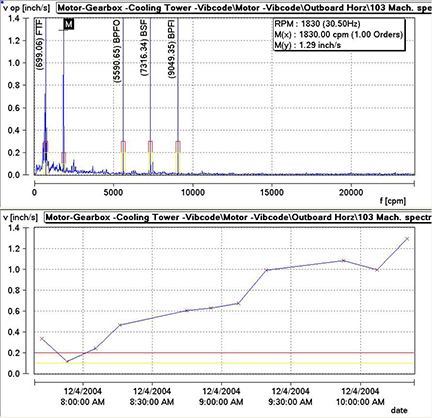
Some vibration software and vibration data collectors allow the use of frequency bands to help the analyst measure and identify specific equipment faults. These frequency bands are actually measured in the vibration data collector. The results can be used for trending and alarm purposes. You can create specific bands around specific faults that may occur in the equipment being monitored. For example, bands for imbalance, misalignment, specific bearing defects, electrical defects, and much more can easily be measured. Alarm thresholds can be created to alert you when attention is required. These bands can help you identify equipment issues in your vibration data before you look at the FFT or time waveform data. A review of the FFT and time waveform data should always be completed. However, band alarms can keep you from overlooking an issue and reduce the amount of analysis that may be required.
by Trent Phillips
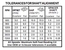 Some coupling manufacturers will sell couplings claiming that the coupling can take shaft misalignment. While this is true for most flexible couplings, it can be easily misinterpreted. Flexible couplings are designed to withstand, without damage, some shaft misalignment. Sometimes it is perceived that, since the coupling can take the misalignment, the machines can run under this condition without any consequences. When running machinery with significant shaft misalignment, bearing and seal life may decrease immensely, and other damage results. Therefore, for longer machinery life, it is always recommended to have equipment laser aligned to standard industry tolerances for shaft alignment, and not to the looser alignment tolerances allowed by the coupling itself.
Learn about Shaft Alignment Tools with Built-in Tolerances.
by Adam Stredel CRL
by Ana Maria Delgado, CRL
Oil data reports made available by laboratories to their customers are usually delivered in MICROSOFT EXCEL® files or text files. The data is generally made available via an online download. These reports contain information on many different substances found in the oil such as iron, aluminum, copper, and many more. Other factors such as viscosity are included as well.
Oil analysis data provides a great insight into the health of your equipment and should be a routine part of any good reliability program. It can be overwhelming to process all this data in a meaningful way. You may not wish to trend and alarm on every single parameter contained in the oil report. So what do you do? The answer may be your vibration analysis software!
A good vibration analysis program like OMNITREND will allow you to create customizable imports for your oil analysis data. A routine and automated process can be set up to import only the data of interest for specific machines. Once the data is imported, then automated alarms can be created to alert you of any oil parameters that are of concern for your equipment.
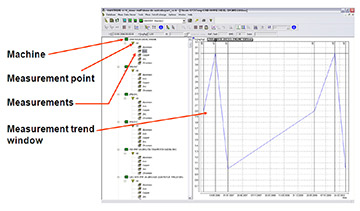
Oil data can be visually trended over time and you will automatically be alerted when an oil parameter reaches a value of concern for a specific machine. This can allow you automatically manage selected oil parameters of concern and greatly reduce the amount of time required to manually review each parameter measured by your oil analysis lab.
Furthermore, it will allow you to use the routine vibration data collected and oil analysis data provided by your laboratory to detect and confirm equipment problems. You should not underestimate the power of having your vibration and oil analysis data integrated.
by Ana Maria Delgado, CRL
MYTH: “It is acceptable to use a stinger attached to the vibration sensor.”
TRUTH: Stingers can be attached and used with most vibration sensors. However, stingers are the least desirable method to mount the sensor to the equipment. Stingers reduce the frequency range that can be measured with the attached sensor. Also, it is very difficult to use the same amount of pressure to hold the sensor to the equipment each time. This may further reduce the signal response as well as the consistency and quality of data.
MYTH: “Applying generic overall amplitude values allows the correct trending and identification of equipment faults.”
TRUTH: An overall level is a single number representing the amplitude of a vibration measurement. Overall values can be derived in many different ways. You should be very cautious when assigning generic and/or the same alarm values to your equipment. Similar machines can operate at different vibration levels. The individual characteristics of each machine should be taken into consideration when setting valid alarm levels.
MYTH: “Collecting vibration data quarterly, semiannually, or annually on equipment will identify all equipment defects.”
TRUTH: The collection frequency of vibration data should be determined based on several factors. Some of these factors are equipment load, the operational speed of the equipment, operational frequency, criticality, and more. It is possible to calculate the optimal measurement frequency required to routinely identify equipment defects. Assigning some collection frequency based upon manpower or other means almost always results in equipment failures that were not detected in time or at all by the vibration program.
by Trent Phillips

