The Reliability Support Team at the Eastern Processing Facility located at Cape Canaveral Air Force Station, FL, won Uptime Magazine’s Best Design for Reliability Program award.

During the design phase of their program, the team was challenged with the implementation of Reliability-Centered Maintenance (RCM) principles and Precision and Predictive techniques from construction through commissioning. These have proven to be the most advantageous with regard to failure mode consequence reduction.
Congratulations to Frank Saukel, Garry Pell, and their team for this prestigious award and a job well done!
Program Highlights
1. Eastern Processing achieved Failure Mode Reduction with added redundancy.
2. They redesigned the facilities’ Reverse Osmosis Water System.
3. They performed Asset Prioritization based on safety, environmental, mission impact, and probability of failure studies.
4. They trained technicians and engineers on RCM. In the words of Garry Pell: “Don’t expect to gain tribal knowledge if you don’t invite them into the Teepee. Get your people involved from engineering to safety, from shipping to operations.”
6. They developed all maintenance procedures based on RCM decisions.
7. They identified the Predictive Maintenance (PdM) technologies and tools they needed, met with different vendors at different IMC Conferences, then focused, implemented, and trained on 1 or 2 maintenance and
Condition Monitoring (CM) technologies annually, including:
• Lubrication analysis
• Vibration analysis
• Laser shaft alignment
• Infrared thermography
• Ultraviolet thermography
• Electric signature analysis
• Ultrasound
Many discrepancies were corrected using these PdM and CM technologies. According to Frank Saukel, “Every one of the PdM technologies has paid for themselves.” For instance, they identified misalignment and motor structure resonance conditions using their VIBXPERT® vibration analyzer on several of their water pumps which had been aligned by a contractor.

Every pump was found to be bolt-bound and base-bound. They realigned all their pumps to excellent tolerance with their ROTALIGN® ULTRA laser alignment tool.

They also found and corrected electrical deficiencies with ultraviolet thermography and detected sub-grade piping leaks with ultrasound. Their precision lubrication program included oil analysis, with a resulting reduction in the number of lubricants, minimization of cross-contamination, and implementation of a color-coded system for easy machine identification and the use of accessories to control moisture. Learn more…
by Ana Maria Delgado, CRL
When performing an alignment on a machine train with a motor fitted with a sleeve bearing, it is important to account for the magnetic center of the motor. Failure to do so can cause excessive vibration and premature failure of motor components and the shaft coupling.
If the motor has recently been rebuilt it should come from the motor shop with a magnetic centerline scribed on the shaft. To properly set the shaft coupling gap do the following:
- Determine the correct coupling gap based on the manufacturer’s recommendation. (Note we refer here to the proper installation gap size and its tolerance, not the alignment gap tolerances for angularity.)• Identify the correct scribe mark on the shaft that represents the magnetic center.
- Measure the distance between the scribed mark and the outside bearing housing lip. In the case that the magnetic center scribe mark falls inside the motor housing while at rest, scribe a mark in the rest position.
- While the machine is un-coupled run the motor and estimate the difference between the newly scribed mark and the magnetic center mark. This is the distance that will need to be compensated for when setting the coupling gap.
- Set the coupling gap according to the manufacturer’s recommendation minus the distance measured for the magnet center correction if the mark is outside the bearing housing. Add the difference if the mark is inside the bearing housing. This will provide the proper coupling gap under the normal running condition.
by Ana Maria Delgado, CRL
The Hibbing Taconite Company, managed by Cliffs Natural Resources of Hibbing, MN, won UPTIME Magazine’s Best Lubrication Program award. At the heart of their condition monitoring efforts is the Oil Analysis component of their lubrication program, key to helping them identify problems at an early stage of failure.
During the first phase of the program, which they called “First Evolution”, reliability engineers were trained as Level I Machine Lubrication Technicians (MLT1). Thereafter, dedicated lubrication mechanics were assigned to the plants to monitor the condition of the oil. They engaged with their vendors to identify needed parts and reviewed their planning, scheduling, and work execution. They selected critical equipment on which to prove the concept.
During Phase 2, MLT1 training continued, including lubrication mechanics and supervisors. Critical equipment underwent lubrication upgrades with the addition of desiccant breathers, sight tubes, sample ports, and quick couplers for filtering, allowing for safer filter changes and reducing cross-contamination risk.
Today, 80 employees have been MLT1 trained on machinery lubrication and basic oil analysis. Employees are fully engaged and enjoy wholehearted management support as significant consumption reduction was realized. Management views the program as an investment.
During their presentation at the IMC-2012 International Maintenance Conference, Reliability Engineer Dan Lerick shared that in certain applications, they have proved a 3.5% energy reduction by switching to synthetic gear oil, which also extended oil drains from 5 to 15 years. Another positive was the switch to synthetic engine oil where they observed a reduction in fuel usage and fueling time, with an extension in engine life and extended drain and maintenance intervals. Overall ROI was under 1 year!
In addition to their award-winning Lubrication Program and as part of their reliability efforts, the company uses CMMS software and other Predictive Maintenance technologies such as Ultrasonic examination, Laser Alignment with ROTALIGN ULTRA, etc. Learn more.
Congratulations to Dan Lerick and his team for this award and a job well done!
Program Highlights
1) Fluid Analysis consolidated across all Cliff operations. They now use a single oil lab after carefully ranking and comparing sample results from eight different labs. The benefit was consistency and the ability to review and compare data.
2) For Fluid Sampling, they developed sample standards per equipment specs, installed sample ports, and trained personnel on how to collect samples. Their CMMS system controls their sample frequency.
3) The use of Grease Systems and Grease Routes wherever possible along with ultrasonic technology on motors.
4) Implementation of condition monitoring (CM) via oil moisture sensors and CM sensors for real-time monitoring. The immediate benefit was a reduction in overall site oil consumption by removing water contamination.
5) Cleaner and safer fluid changes with the use of dedicated Lube Carts to eliminate drips and spills.
6) All machines were tagged with machine identification and lubrication information to reduce mixing and cross-contamination.
by Ana Maria Delgado, CRL
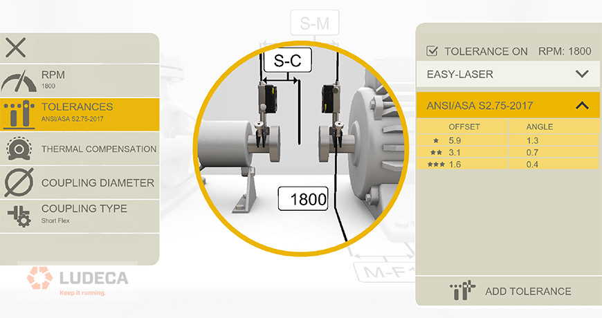
 We are proud to release a new version of our “Laser Align” mobile application. The app is available in the iTunes Store for both iPhone and iPad; as well as in Google Play for Android. The application now has an interactive Tolerance Table, where the user can input his own machine RPM and the app will kick back the respective Alignment Tolerances for both short flex and spacer type couplings. It also includes a Thermal Growth Calculator and now has a Soft Foot Assistant to help the user interpret soft foot values.
The app is available everywhere for FREE. Download now.
by Adam Stredel CRL
We recently ran a poll to find out what the Top Machine Faults are for the attendees of the IMC-2012 International Maintenance Conference. Here are the results, which came from maintenance and reliability professionals who attended our Learning Lab:

Misalignment: 32%
Bearing Failure: 31%
Unbalance: 18%
Looseness: 16%
Other: 3%
The good news is that all our lab participants were acquainted with our Condition-based Maintenance tools which can help them detect, prevent and correct all these problems.
It is essential to understand how equipment performs in a facility and to be able to identify these common machine reliability issues before they result in functional failures in your equipment. Payback technologies like vibration analysis, alignment, and balancing when part of a comprehensive condition monitoring program can improve your equipment performance, reduce equipment downtime and minimize risk.
by Ana Maria Delgado, CRL
Rotalign® Ultra LIVE TREND is by far the most cost-effective and technically competent tool to monitor pipe strain per API standards. LIVETREND allows maintenance personnel to monitor and record digitally the alignment offset changes at each coupling hub face, thru the entire bolting procedure, as specified, while comparing it to the final unit alignment if desired.” —Marty Krueger, Tern Technologies, Inc.
API 686 (Chapter 4, Piping Alignment) notes that the basic method of verifying pipe strain and its effect on the machinery is to monitor shaft alignment with dial indicators or lasers thru the machine flange torquing procedure. API 686 allows that an alignment change of +/- 0.002″ is acceptable while monitoring at the hub of the opposite machine (unless there is common piping between the two machines, then alignment changes should be noted at both hubs).
LIVE TREND allows the user to monitor the alignment change at both hubs, simultaneously and in real-time (at a user-specified data collection frequency) through the complete piping/flange torque procedure. The system program also allows the user to “flag” and note each step of the procedure (suction line complete, discharge line complete, etc.). LIVE TREND also allows the user to enter the final shaft alignment values (or actually take the final shaft alignment prior to start and import that data into the LIVE TREND program) so that the user not only can note the changes at the hubs as a result of the pipe/flange torque but also to note immediately if the change is within (or exceeds) the final alignment tolerances if the movement exceeds the +/- spec as per API.
It should also be noted that the LIVE TREND can be used to monitor the alignment thru the “Spring Hanger Function Checks” and any effects of possible piping strain to the machine during tear down, prior to overhaul, to give the user advance warning (and subsequent time to plan) for possible piping issues that might arise during reinstallation and re-attachment of piping.
by Ana Maria Delgado, CRL
Vibration analysis is the best all-around technology for diagnosing and predicting problems in rotating machinery. Over the years I have seen time and time again where adopters of this technology have saved themselves and their companies countless man-hours and thousands of dollars by getting to the root cause of a problem early on. By analyzing the data, they are able to schedule their valuable time on the right problem on the right machine long before the problem escalates into a major outage or emergency. But too many companies have not adopted vibration analysis. While it is true that one could spend many years learning the skills of the multiple levels of the vibration analysis disciplines, it is also true that even a basic understanding of the relationship between the time waveform and the spectrum can yield huge benefits and savings to a new user.
For example, the root cause of most roller bearing/seal failures is either shaft misalignment or rotor imbalance, which can take months to develop. It is also the most common problem analyzed within most facilities in the first two years of vibration analysis implementation. The good news is that misalignment and rotor imbalance are the easiest problems to diagnose by observing a high amplitude 1× running speed frequency in the spectrum. After that, a phase analysis with your analyzer can easily differentiate between misalignment or an imbalance problem and quickly completed without shutting down the machine.
We all know that Rome wasn’t built in a day but we all must start somewhere and just a few days in an analysis class could yield major benefits to new companies.
Thanks to Jay Gensheimer with Solute LLC for this valuable post.
by Ana Maria Delgado, CRL
Often, seal failures are not the cause of an incorrect installation or the wrong seal type for the product being pumped, but a symptom of misalignment. If a seal starts dripping or misting product within days after installation, or suffers a “catastrophic” failure within weeks of being placed in service, the first suspect should not be the seal vendor or the technician installing the seal; misalignment should be considered as a good candidate for the cause of failure. Visualize a typical pump-motor system of bearings, shafts, seals, and coupling. The weakest link in the chain is usually the mechanical seal. In the last ten years, seal technology has progressed substantially in both material composition and design (most notably cartridge seals), in compensating for shaft vibration.
However, significant misalignment can still overwhelm the ability of a seal to keep both seal faces pressed firmly together or to withstand seal face cracking.
So remember, the next seal failure you encounter, quickly check misalignment with a good laser alignment system to see if the weakest link has failed due to misalignment.
by Ana Maria Delgado, CRL
There are several ways of looking at alignment tolerances, including standard versus vector tolerances, as well as sliding velocity tolerances. The most used are standard tolerances, but which are applied differently for short flex versus spacer couplings. The best laser shaft alignment systems will allow you not only to select tolerance types but also coupling types. For standard tolerances, keep in mind that the vast majority of true flexible couplings (such as gear, grid, elastomer element, or diaphragm type) have two separate flex planes. So do all spacer couplings. The difference between short flex and spool piece, spacer, or jackshaft couplings lies in the distance between these flex planes. Any time the distance between flex planes is greater than the diameter of the working flex plane, you are better off calling it a spacer rather than a short flex, from the perspective of achieving satisfactory alignment.
Keep this in mind when selecting coupling type, as it will greatly increase the alignability of the machines, and ease your job in the field. For a deeper understanding of the subtleties involved in these issues, it is recommended to attend an in-depth training course in laser alignment.
Check out the Easy-Laser XT Series, the only laser alignment platform on the market today with the new ANSI alignment tolerances built-in giving the user the freedom to choose between traditional tolerances, the new ANSI standards, or custom tolerances of the user’s own choosing.
by Ana Maria Delgado, CRL
When performing a multiple belt-sheave alignment, it is imperative that all the belts and belt grooves are inspected individually for wear. If any of the belts are slipping, then all belts must be replaced at the same time. To achieve an accurate alignment between the pulleys one can use a machinist’s straightedge, or place a tightly drawn piece of string, across the faces of the sheaves to see if all four points of contact are made or you can utilize a Laser Pulley Alignment tool. Regardless of which system is used to perform the alignment, it is a good practice to monitor any changes in angularity and/or offset in the sheaves as the hold-down bolts of the machine to be moved are being tightened during the belt tensioning procedure, since this will allow the sheave alignment to be maintained true.
by Ana Maria Delgado, CRL
I have been using the ROTALIGN® ULTRA for about one year now and it has made my job easier and faster. I like the ease of the installation of the tool. No more need to multiple dial indicators and carrying different mounting brackets! Everything in the ROTALIGN ULTRA is snug and compact in its own case. All I have to do is grab it and go! The ROTALIGN ULTRA is by far one of the easiest computer-based tools I have ever used; from installing it on the machine to navigating through the screens. One of my favorite options is the “constant sweep” mode. Once you get your laser set and you’re motor data programmed, just hit “go”! Another nice feature is the “Soft Foot Wizard”. No more fighting with dial indicators on each foot pad. The ROTALIGN ULTRA is so effective, it even tells you how much to shim on each foot pad! This has saved me so much time and hassle.
I have used the ROTALIGN ULTRA for Land O Lakes, Disney Land Theme Parks, Rexam beverage, Guardian Glass, Alza Corporation and many more.
One of my favorite things about the ROTALIGN ULTRA is the ease of giving the customer a report as soon as I’m done with the job. I’ll I have to do is save my report and transfer it to a thumb drive. At that point, I take it to the customer and have him save it to his computer! No more need to go back to the shop, download it to my computer and print!
I have done a lot of research on other brands of laser alignment tools and have had the sales representatives do demonstrations on them but when the representative for ROTALIGN ULTRA came to Capitol Air Systems for his demonstration, I knew this was the one for us. It was one of the best demonstrations hands down and the representative even let us get familiar with the operations of it. The time that the ROTALIGN ULTRA has saved me has well paid for itself. —Lonnie E. Owens, Sr., Sr. Field Service Engineer, Capitol Air Systems.

by Ana Maria Delgado, CRL
Many end users have taken laser alignment equipment and “checked” alignments on equipment that has been running satisfactorily, and very often with vibration data that falls well within alarm thresholds, only to find the alignment out of normal alignment tolerances. In this instance, the vibration data should be the determining factor. If the equipment is running well, leave it alone. It would however be a very good practice to keep this alignment data and use it in the future for the intentional misalignment of this particular machine. It is quite possible that the machine had in fact been deliberately misaligned when cold and stopped to compensate for positional changes that occur due to thermal growth or dynamic load shifts.
by Ana Maria Delgado, CRL
Laser shaft alignment has become ubiquitous these days. And for the most part, alignments are very similar from one machine train to another. The user enters the RPM for tolerance evaluation, enters the dimensions of the driver, measures misalignment, and makes corrections. But what happens when an unusual physical configuration exists, as when the foot of the machine is between the flex planes of the coupling? Or the receiver cannot be mounted outboard of the flex planes of such coupling?
Entering a dimension correctly as a negative value can take care of that problem. This will ensure that the corrections at the feet are precise, and the alignment is done properly.


Does your laser alignment system have this crucial capability? Our ROTALIGN® ULTRA laser alignment system does!
by Adam Stredel CRL
Do your analysts use consistent phrases or statements when creating condition monitoring (CM) work orders? It is very important to convey concise and accurate information with each CM work order. Often times misspelled words, inaccurate information, or incomplete maintenance steps are included in work orders. A best practice is to determine the most common findings for a specific CM technology and determine what actions should be taken as a result. For example, if vibration analysis identifies unbalance in a fan, a recommendation should be made to clean the fan prior to attempting to balance it. If a CM technology identifies a failure that requires the machine to be removed, then re-alignment may be necessary before the machine is placed back into service. All of these steps and perhaps additional steps should be conveyed by the CM analyst creating the work order.
Creating consistent and detailed steps for common CM problems will avoid forgetting to convey important information to those doing the work. This will help ensure that best practice maintenance is completed on your equipment, things are not forgotten, misspelled words entered, or other common mistakes made.
by Trent Phillips
When dealing with a gearbox that has 3 feet, there are two possibilities:
a) If the feet are located under the shaft and bearing housings, view the gearbox as a normal 4-foot machine. This will give you inboard and outboard corrections for the feet. The end that has the 2 feet should be corrected evenly, and the 3rd foot should be corrected as per the screen.
b) If the feet are on the sides of the gearbox, or NOT under that shaft or bearing housings, then configure the gearbox as a 6-foot machine. This will give you corrections for the inboard, middle and outboard feet. Correct accordingly at each foot.
by Ana Maria Delgado, CRL
In any alignment situation, one of the most basic principles is rise over run. Think of it as a change in offset over a distance. It is also a way to quantify angles without using degrees. When the laser system measures “angularity”, it expresses it as rise over run, or a change in offset over a distance. This information, along with the dimensions that the user enters is what the system uses to calculate corrections at the feet. That is why it is very important that laser measurements are repeatable and that all dimensions should be accurate to within 1/8 inch. The sensor to coupling dimension is the most critical of these. If the laser measurements are good but the dimensions for the feet are not, any corrections the computer calculates will not work due to the fact that they are “applied” to a different location, not at the actual foot location. If you are making the corrections that the computer says to and your alignment is still off, double check your dimensions.
by Ana Maria Delgado, CRL
In my spare time, I enjoy the hobbies of building bicycles and metalworking. There is something about making things from scratch that satisfies both the kid and engineer in me.
I recently sold a hobby class CNC machine that I purchased about a year ago. It was a capable machine for what it did and the price was MUCH less than the typical Vertical Machine Center (VMC) that you would see in a machine shop. Unfortunately, it didn’t do exactly what I needed. I learned through further education that my machine “should have this capability, must be able to do that, etc.” I also found out that much of the manufacturer’s verbiage such as “step resolution,” “precision,” “computer-controlled,” “complete solution,” and “high quality” was bandied about so much that one would wonder why a machine shop would pay so much more for a quality CNC VMC. Upon talking to other users, I learned more about its shortcomings and what they eventually did: they were now educated and instead invested in machines that actually did what they needed for their applications and delivered on the manufacturer’s promises. Haven’t we all experienced this same situation before when buying cars, TVs, appliances, cell phones, etc.?
Unfortunately, this situation is not isolated to CNC machines and consumer products but extends to all sorts of products – even laser shaft alignment systems. If you make an internet search for laser shaft alignment tools, terms such as “.0001 resolution, laser, high precision, easiest, 3000 points, 60-degree turn, single correction alignments, etc.” are thrown about on websites and it is unfortunate that customers must sort through this and hope they find a laser alignment tool that will truly satisfy the requirements of their reliability program.
How can you make the right decision in buying a laser alignment product? For starters, inform yourself through reliable sources. I would encourage you to talk to other users and get their experiences with the tools. These are people that use shaft alignment for their reliability program. Maybe they have purchased a variety of tools before settling on the right tool that works. Let their experience help save you time in searching for the right product.
I would also encourage you to contact your vendor and ask for a demonstration. Everyone claims to have the best product, but the real proof is that the tool actually works for your reliability program. For example, if you contact us, we have knowledgeable local representatives and an onsite dedicated engineering staff who will gladly visit your facility and answer any questions you may have. We have represented Prüftechnik (the inventors of laser shaft alignment) for 30 years and many of our reps have represented our products for over 25 years. All those years mean that we have the experience, references, and reputation to provide you with the information and resources to make an informed decision.
Buying a laser alignment tool is essential to your reliability program. Its ultimate goal is to reduce the amount of time to do alignments, do them more accurately, and document the results. Doing so will help you accomplish the main goal – improving the reliability of your plant and thereby saving time and money.
by Daus Studenberg CRL
PUMPS & SYSTEMS • August 2012
By James Laxson, Hi-Speed Industrial Services in collaboration with Mike Fitch, LUDECA, Inc.
In May 2010, an electric motor repair service provider in Little Rock, AR, began a condition monitoring program for a new customer. The customer opted for quarterly data collection.
Read the article Pump Train Component Failure, a briefcase history of a component failure in a nominal 1,800 RPM pump train.
by Ana Maria Delgado, CRL
Dial indicators can fluctuate several thousandths; no direct solution to this is available. However, with ROTALIGN® ULTRA, as with the OPTALIGN® SMART and SHAFTALIGN®, a measurement setting known as “Averaging” can be controlled (Figure 1). The averaging feature allows you to control the number of individual data points taken per reading. If there are high vibrations, or positional fluctuations being picked up by the equipment, increasing the averaging can ensure that you obtain a true measurement of the misalignment.

Figure 1 – Averaging Feature
Further data collection analysis can be accomplished after the alignment measurements have been taken by viewing the scatter plot of all individual points/readings using the “Edit Points” feature (Figure 2). With the advanced functionality of ROTALIGN ULTRA, the points with maximum deviation can be found and analyzed (Figure 3). If, for example, one or more points were found to be random, outlying, high vibration peaks, those particular points can be disabled. By disabling the “rogue” points, the Standard Deviation (SD) of the averaged alignment measurement is decreased, thereby giving you an even more accurate representation of the misalignment (Figure 4).

Figure 2 – Scatter plot of data points (Edit Points Screen)


by Ana Maria Delgado, CRL
Problem Overview
A customer approached LUDECA with a machine train alignment consisting of a fan coupled to a fluid drive coupled to a motor. This particular machine train had limited movement/adjustment available (See Figure 1).

Due to the nature and geometry of the machinery, the fan on the left was stationary, and both the fluid coupling and motor were movable machines. Additionally, the fan could not be rotated. With these limitations and constraints, very careful planning was needed.
Solution
Upon arrival at the site, the LUDECA Field Service Engineer and site personnel began to analyze the situation and figure out the most efficient way to align the machine train. Using the advanced functionality of the Rotalign® ULTRA, uncoupled readings were taken across the fan and fluid coupling, and coupled readings were taken across the fluid coupling and motor. The “As Found” results can be seen in Figure 2.

Per the request of the customer, the alignment was to meet “Short-Flex” Tolerance requirements, even though the coupling was in fact a large gear coupling whose flex planes (points of power transmission) were 13 inches apart. Upon performing the horizontal correction of the motor it became bolt-bound, which prevented further movement in the required direction, New readings were taken and the misalignment is shown below in Figure 3.

Due to the Short-Flex tolerance requirement, the motor needed to move further on both the inboard and outboard feet than was possible. To achieve the Short-Flex tolerances would require very tedious corrections, involving additional movement of both the motor and fluid coupling, or in a more extreme case, re-machining of the bolt holes in the motor feet to allow for more movement. The LUDECA Field Service Engineer suggested that Spacer Tolerances be used. With Spacer Tolerances, the large axial distance between flex planes is taken into account in such a way that the angle at each flex plane is examined individually. This can be done by examining these angles directly in mils per inch, or as the projected offsets of the machine centerlines to each flex plane across the distance between them. With the tolerances set to the spacer-type coupling, the results were viewed once again and it was discovered that the alignment was, in fact, within proper tolerances (See Figure 4). By changing the coupling type from Short-Flex to Spacer, what would have been a tedious and time-consuming task was found to be unnecessary, and was instantly resolved by entering the appropriate coupling type, in this case, spacer coupling. The spacer-type coupling takes into consideration the distance between flex planes, whereas short flex-type ignores it.

by Ana Maria Delgado, CRL