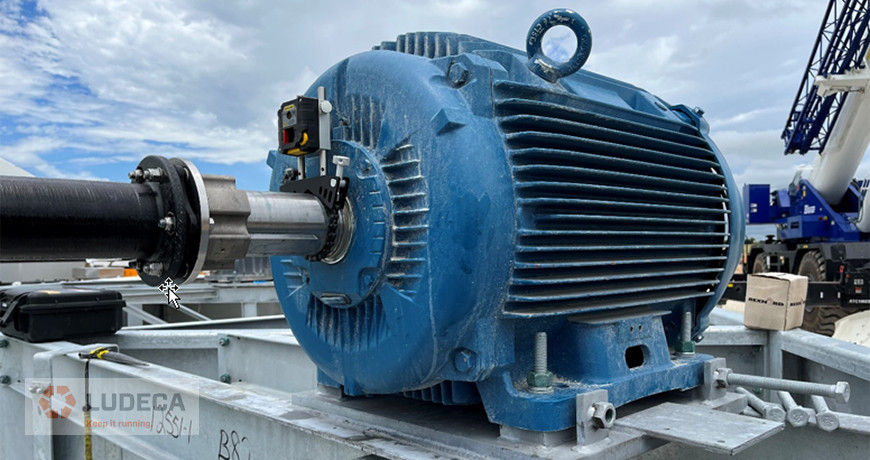
Two new hires called into our office for help with an alignment they were doing with a newly bought Easy-Laser XT laser shaft alignment system. Fortunately, our chief engineer was able to remotely guide them through two successful gearbox-motor alignments. There was still an issue: these gentlemen were inexperienced and being tasked with aligning 20 additional similar setups for cooling towers, in peak Texas heat. The first alignment revealed that our motor, Machine To Be Moved (MTBM) was both base- and bolt-bound. The second alignment also found the motor to be both base- and bolt-bound. Every single cooling tower had identical gearboxes and identical motors that sat on identical “frames”. By the third alignment, a clear pattern formed. This was no coincidence, the jackshafts were 110 inches long, with machines that weren’t centered prior to installation. Small amounts of angular misalignment at the gearbox are enough to cause a bolt- and base-bound condition as the offset produced by the angularity is magnified across the long distance of the jackshaft’s length, making the resulting correction to be performed too large at the motor. An angularity of 0.5 mils/inch is enough to cause a 55-mil offset between the machine shafts at a 110″ separation. It is apparent that it doesn’t take much angle to run out of space in the anchor bolt holes at the motor. The motor sat higher than the gearbox while both machines sat angled slightly downwards, looking towards the center between them.
After realizing they were bolt-bound many experienced alignment technicians would elect to use “Chicago” bolts or undercut bolts, which are designed to allow for a little additional freedom of horizontal movement of the machine. Obtaining them likely would waste several hours, even with a machine shop on site. Another approach is to drill bigger holes in the feet. However, our two junior aligners saved on what could have amounted to several days over the course of all 20 alignments by instead performing optimal moves. An “optimal” move is a small adjustment made to the Stationary Machine (the gearbox in this case) that eliminates the need for the large projected corrections at the Motor. It is the smallest feasible move that will accomplish this objective. In these cases, both front feet were brought up, which is easy to do, since adding shims is always easier than removing them if they aren’t there to start with! This saves time and is generally the most efficient approach to the base-bound situation. In this case, the gearbox was free to move, no piping or another machine coupled to it, so it was a no-brainer. Undercutting bolts is popular because piping and electrical conduit along with other factors make it difficult and, in some cases, impossible to move one of the machines. In any case, an optimal move is worth considering at the very least. As long as your stationary machine is able to make the SMALL move necessary you will save yourself time. Very little risk considering it, bountiful rewards if it makes sense. It is up to the technician to use their judgement and experience to determine if this is possible and worth the effort.
The third alignment needed two vertical moves to get it within Precision (ANSI/ASA S2.75-2017) Tolerance. The first correction was to shim both gearbox and motor front feet up, this got rid of the base-bound condition at the motor. The second move was to shim all four motor feet up. One horizontal move was necessary via gearbox to get out of bolt-bound condition, no jackbolts on the machine so a hammer was used. Every setup was the same, allowing our junior aligners to employ the template feature of their XT laser system and save more time there as well.
Filed under:
Alignment, Articles and Case Studies by Jim Larochelle
