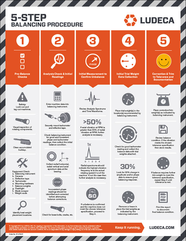
Precision balancing is an essential part of a proactive reliability program as it can eliminate many machine failures and defects. This Infographic outlines an easy and effective way to balance your rotating equipment. Download Infographic
In today’s world, video platform is the way to accomplish effective visual knowledge and a learning mechanism in many organizations. With the use of video, one not only is able to promote products and services but one can also strengthen a culture and demonstrate how-to scenarios easily and quickly. Video Library
LUDECA believes in communicating visually to help customers educate and train their personnel on precision skills. For this reason, we are pleased to announce the release of our new microsite www.LudecaVideos.com, which features a Shaft Alignment Know-How series plus a Know-How series for Vibration Analysis and Balancing. The video site features basic terminology, fundamental concepts, advanced measurements as well as product demonstrations. The videos are indexed by category but also searchable by keyword.
We felt there was a need to go back to basics and help educate on precision skills and related technology to improve asset reliability. Following the Uptime Elements™ holistic approach to reliability, alignment and balancing are key components of your asset condition management (ACM) program. We are happy to offer these videos to our customers for their personnel to access and for use in their training programs. We hope this content assists them and others in either improving their reliability program or in getting one started and leads to world-class reliability programs,” —Frank Seidenthal, president of LUDECA.
We encourage you to visit www.LudecaVideos.comand see for yourself the value behind each video.
The following blog relates to those who field balance using a photo or laser tach and reflective tape.
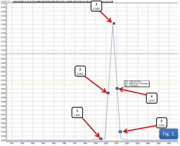
By far the most common pitfall to field balancing is a problematic tach signal. When one balances a rotor using one’s field balancing unit (VIBXPERT® II, VIBXPERT, or VIBSCANNER®) the equipment is recording the energy displayed at the frequency of the signal from the tachometer. To help visualize the importance of a clear tachometer signal that is exactly 1 pulse per revolution, look at figure 1.
What amplitude will your equipment record if the tach pulses:
1. 1,195 times per minute?
2. 2,002 times per minute?
3. 2,006 times per minute?
4. 2,011 times per minute?
5. 2,013 times per minute?
We often start a balance job by haphazardly placing our tach and tape. Because both the tach and tape are well-engineered, we may go on without a problem. But just a little attention to some of the common tach signal problems is usually all it takes to avoid having to restart a botched attempt at field balancing. What should be avoided when setting up a tachometer?
1. Don’t place your tach too close to the rotor. Most tachometers are used in the fieldwork sending some type of light out and bouncing it back, so they have a sending function and a receiving function. The wavelength of the light is such that not just any light will be accepted by the receiver, but only that wavelength of light sent out by the sending unit. So the receiver counts a pulse every time that wavelength of light appears (or disappears, depending on whether you are triggering by leading or trailing edge). The receiver is no smarter than that, we must supply the rest of the intelligence. When we put the receiver too close to the rotor, even a poor reflector may be able to bounce back enough of the light signal to create a pulse. The balancing technician should determine the distance from the rotor to set up their tach with the understanding that they want a good signal bounced back from their chosen reflector AND ONLY THEIR CHOSEN REFLECTOR! Most often, a 6-inch space is sufficient.
2. Don’t place your tach pointing perpendicular to the rotor. Earlier we stated that “both the tach and tape are well-engineered”. One thing most of us field balancers take for granted is the reflective tape. This tape is actually a well-engineered tool. Reflective tape is faceted in such a way that light can strike it at an acute angle, and still be reflected right back along the axis from which it came. This allows the tach to be staged at such an angle that light will strike the rotor, even a rotor that is itself a good reflector, and be reflected off and away from the receiver UNTIL the tape comes into the line of the light, and then with its special faceting, it will bounce the light back to the receiver. This gives one clean pulse every time the tape comes around, and only when the tape comes around.
3. Don’t use old reflective tape that may not be in proper working condition. Make sure the tape is clean and in good shape. Reflective tape works very well when it is clean and in like-new condition, but can get dirty or even deteriorate if conditions are right. Replacing a small piece of tape is most often very quick, easy, and cheap compared to extra balancing runs or possibly even worse.
4. Don’t use a tach with dirty lenses. Make sure the tach lenses are clean and in good shape. When your lens is dirty, it forces you to do things (in order to get a strong enough signal to go through the dirty lens) that aren’t conducive to a clean, clear, once per revolution pulse; like move the tach too close to the rotor, or place it at a 90° angle to the rotor.
Doing everything we have suggested here could take all of 5 minutes (if you work slowly) at the beginning of a field balance job, but it could save a lot!
Recently I visited a customer’s facility to provide onsite training for the VibXpert® vibration data analyzer they had recently purchased. Before we could get started collecting data, we needed to build the equipment hierarchy and measurement templates required. Once the database was created, we loaded routes into the VibXpert and proceeded to collect vibration data.
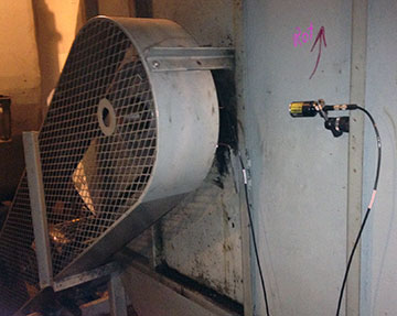
The first room we entered had two large belt-driven overhung fans. At first glance, it was obvious that one of the fans was running extremely rough. We collected vibration data on both fans and paused to review the results. We noticed that the 1× amplitude on the rough fan was over 1.0 inches per second peek. The local CM technician immediately commented that the fan should be balanced and his observation was correct when simply looking at the vibration data.
The room was full of clues that explained the cause of the fan unbalance. This facility processed and manufactured wood products. Large amounts of wood dust are produced and these fans were designed to ventilate a high dust area. Everything in the room was covered with wood particles and dust. The only question was how much had accumulated on the inside of these fans.
I asked if the fan could be stopped for a short period and the inspection door opened. My request was honored and the fan was shut down and locked out. Our examination revealed the fan blades had amassed substantial amounts of wood particles. The fan blades were cleaned and resulting in a pile of wood chips weighing about 5 lbs. The fan was placed back into operation and allowed to run for several minutes. Vibration data was recollected on the fan and the 1× amplitude had reduced to 0.1 inches per second.
Fans require corrective action to eliminate unbalance conditions from time to time. However, the cause of unbalance may simply be a buildup of foreign matter on the blades. This fan was being allowed to beat itself to death due to product buildup. This facility learned a few lessons from the experience. First, inspections utilizing the human senses (touch, hearing, etc) could have been used to determine that this fan was in need of attention.
Second, periodic vibration monitoring would have identified a need for maintenance on this fan. Third, if a fan is properly balanced, simply cleaning foreign matter buildup may reduce the vibration, prevent equipment damage and maintain the reliability of the equipment. Make sure that you utilize these three steps during your daily maintenance efforts on equipment.
I have been using the VIBXPERT® II Balancer for a year. I have balanced fans ranging in size from 10, 000 to 1 HP, mostly within 3 shots. My last customer had a contractor quoting a fan rotor replacement. Using the VIBXPERT II, the fan was balanced to 2 mils from 25 mils in 3 shots. The customer cancelled the fan replacement. The ability to acquire and view spectrum, review cost down data, and perform resonance testing are features not found in other balancers. —Victor Galanto, Fan Services Associates
If you want to find the secrets of the universe, think in terms of energy, frequency and vibration.” ? Nikola Tesla
Could Tesla’s secret be the energy wasted due to vibration at a frequency equal to shaft speed all caused by rotor unbalance?
Balanced rotors are critical for achieving production and profit goals. Unbalance creates high vibration, which leads to other faults resulting in decreased machine life, wasted energy, and reduced efficiency. Smooth-running machines are required for producing products that meet customer specifications. The IOSR Journal of Mechanical and Civil Engineering states that rotor unbalance is the major cause of vibration problems. A good balancing process is essential for successful physical asset management.
As more and more wind turbines are coming out of warranty, the industry is focusing on making sure that the assets they have in place are in proper running form. If it is the gearbox, the generator, and/or the rotor blades, they need to be inspected and/or checked.
In the case of the rotor blades, if they have had any sort of work performed on them such as repairs after lightning strikes, moisture in the blade, removal and/or addition of coating on the blades, etc. It is good practice to check the mass unbalance. Checking mass unbalance first and then performing the balance job, this will constrain the vibration levels to acceptable tolerances such as the VDI 3934. It will also help reduce the amount of wear on the rolling elements and gears.
Is your equipment considered a slow-running speed machine? If so, what speed do you consider slow? Is it 30 RPM? 60 RPM? 100? 200? 600?
No matter what you consider slow speed, the two most critical points to consider for slow running equipment are:
1) Does your vibration sensor (accelerometer) have the appropriate frequency range to measure low frequencies?
2) Does your vibration analyzer and/or online monitoring system measure down to those frequencies?
Unfortunately, some vibration analysis devices on the market are not truly capable of measuring slow-speed equipment and providing a true mechanical diagnostic analysis. These devices can actually create a reactive maintenance result that the device was supposed to prevent.
For example, a motor shop in South Texas had completed a rebuild of a 100 HP motor. The motor is used in the oil and gas industry. It has an average running speed of 30 RPM. The customer tested the motor on their motor test stand. As it was in its test cycle, the vibration was measured using a self-diagnostic vibration analyzer. The results and diagnostics the analyzer provided to the customer were “please replace bearing”. After several further tests running the motor on the test stand, the customer refused to accept those results and retested the motor using a VIBXPERT® II analyzer with machine templates designed for slow running machinery and a VIB 6.147 low-frequency accelerometer.
The final analysis revealed a high unbalance condition on the motor (11 mils peak-peak). The motor shop followed up with a balancing job (single plane) on the motor. The balancing was performed with the VIBXPERT II as well. Subsequent tests showed that the unacceptable low-frequency amplitude that had been observed (11 mils pk-pk) prior to performing the balance job had now disappeared. Final mechanical diagnostics showed no problems and the bearings were in proper condition. A balance report was printed and the motor was ready to leave the shop.
If you want to increase your uptime and availability and reach your financial goals, proper investment in Condition Monitoring and reliability will provide a positive return on your investment.
We recently ran a poll to find out what the Top Machine Faults are for the attendees of the IMC-2012 International Maintenance Conference. Here are the results, which came from maintenance and reliability professionals who attended our Learning Lab:
Misalignment: 32%
Bearing Failure: 31%
Unbalance: 18%
Looseness: 16%
Other: 3%
The good news is that all our lab participants were acquainted with our Condition-based Maintenance tools which can help them detect, prevent and correct all these problems.
It is essential to understand how equipment performs in a facility and to be able to identify these common machine reliability issues before they result in functional failures in your equipment. Payback technologies like vibration analysis, alignment, and balancing when part of a comprehensive condition monitoring program can improve your equipment performance, reduce equipment downtime and minimize risk.
Vibration analysis is the best all-around technology for diagnosing and predicting problems in rotating machinery. Over the years I have seen time and time again where adopters of this technology have saved themselves and their companies countless man-hours and thousands of dollars by getting to the root cause of a problem early on. By analyzing the data, they are able to schedule their valuable time on the right problem on the right machine long before the problem escalates into a major outage or emergency. But too many companies have not adopted vibration analysis. While it is true that one could spend many years learning the skills of the multiple levels of the vibration analysis disciplines, it is also true that even a basic understanding of the relationship between the time waveform and the spectrum can yield huge benefits and savings to a new user.
For example, the root cause of most roller bearing/seal failures is either shaft misalignment or rotor imbalance, which can take months to develop. It is also the most common problem analyzed within most facilities in the first two years of vibration analysis implementation. The good news is that misalignment and rotor imbalance are the easiest problems to diagnose by observing a high amplitude 1× running speed frequency in the spectrum. After that, a phase analysis with your analyzer can easily differentiate between misalignment or an imbalance problem and quickly completed without shutting down the machine.
We all know that Rome wasn’t built in a day but we all must start somewhere and just a few days in an analysis class could yield major benefits to new companies.
Thanks to Jay Gensheimer with Solute LLC for this valuable post.
Thank you for joining us for our Webinar The Field Balancing Mine Field by Greg Lee. We hope you found the presentation to be valuable and very informative. If you missed our Webinar, you can view the recorded version at any time. Watch now!
Here are Greg’s answers to your questions:
Q: Do you have experience balancing cooling towers?
A: Yes. Cooling towers are interesting because there are a number of causes for vibration. One very dangerous condition that can look like unbalance is a cracked hub. This can lead to a catastrophic failure of the hub, allowing the blades to break free and wreak havoc on anything near. I once saw the result of a hub failure that caused the gearbox to break through the wood mounting frame and fall into the water tank. The motor was still running with a 12-inch piece of jackshaft flailing around.
With cooling towers, it is especially important to run a complete vibration analysis before attempting to balance. The customer in the example above had another cooling tower cell with the same cracked hub problem. We caught that one before the failure using the VIBXPERT II vibration analyzer. It was showing a high 1× radial vibration as one would expect from unbalance. In addition, it was showing a high 1× axially, as large as the radial. The spectrums also showed high 5×, 20×, and 25× frequencies as the blades bobbed up and down as they passed the 4 main gearbox supports and the jackshaft. This is derived from 5 blades times 4 supports for 20× and 5 blades times 5 (4 supports and 1 jackshaft) for 25×.
Q: What about a multiplane, multi pickup balance? i.e. Nuclear rotor train, 4 rotors, 8 bearings?
A: I am not sure what your exact question is, but, multiple rotors in a single train can be complex to balance. If the cross effect from plane to plane is large, the complexity grows exponentially. I worked with a field engineer that balanced a long train of 4 generators and 2 steam turbines using the trial weight field balancing method. It took him a week to balance this system of rotors and bearings.
For something as complex and expensive as you describe, I would bring in the OEM or a company that specializes in Nuclear Turbine applications. Because of the number of bearings, they would most likely use a 16- or 32-channel dynamic data recorder versus trying to use a typical two-channel field balancer.
Q: To select a trial weight, is there a ratio between the machine weight to trial weight to get the correct change in phase or amplitude?
A: Many of the companies that produce field balancing equipment have developed proprietary formulas to calculate how much trial weight to use and where to place the weight. The intent of these formulas is to obtain a 30% change in amplitude and/or a 30% change in phase angle. It should be understood that these derived trial weights are guides, not an absolute. In most cases, these formulas take into account rotor weight, speed and the amount of initial unbalance. The instrument then calculates the suggested trial weight and its position.
There are a number of “Trial Weight Formulas” used. For example, the United States Department of the Interior Bureau of Reclamation recommends that the “trial weight should be approximately equal to the weight of the rotating parts divided by 10,000.” Most of the time in the field balancing the weight of the rotor is not known or is at best a rough guess. In these cases, it is advisable to look at the correction weights previously placed on the rotor and use these as a guide.
Q: How do you determine if it is hydraulic imbalance instead of mechanical?
A: By hydraulic unbalance, I take it that you are referring to internal hydraulic forces in a pump. Fans can experience similar interference from wind. Unbalance will manifest itself at exactly 1 time the running speed. The unbalance vibration amplitude will be exhibited primarily in the radial direction. If you see a lot of axial vibration (50% or more of the radial) then you likely have additional problems that are not balance-related.
For hydraulic problems, look for an additional frequency equal to the number of vanes times the running speed. Hydraulic instability in a pump is often seen in spectrums as low-frequency broad-banded vibration below the running speed. Often, hydraulic problems are accompanied by cavitation. There are specific Shock Pulse measurements that will help you identify cavitation.
Q: On a balance stand, ideally you would want to be at running speed. Most of the time this is not possible due to size/mass etc. How much difference does it make if you can only run at slower speeds such as 30% of operating RPM?
A: First, it is important to understand that balanced is balanced at any speed. For an object to be balanced, the rotational centerline and the mass centerline must be the same. This will hold true at any speed. Because of this, it is not necessarily true that the best stand balance is at running speed. For clarification, please refer to the first few slides of the presentation.
Now, to the answer: In general, as long as one is away from the rotor’s critical resonance speeds, it is fine to balance a rotor at a speed lower than running speed. No percentage rule is necessary. Just stay away from critical speeds. With that said, there are some differences between balancing machines. There are two primary types of balancing machines; a Soft Bearing Machine and a Hard Bearing Machine. Both types have advantages and disadvantages.
Soft Bearing Balancer A soft bearing balancer allows the rotor ends to move freely in the horizontal direction in the balancing stand. This type of balancer allows the rotor to turn at much slower speeds than the rotor’s operational speed. The balancing procedure is almost identical to field balancing and a calibration or trial weight is used to test the response of the rotor. In this way, each rotor balance is in essence self-calibrated. Like field balancing, multiple runs are required and the correction and trim weights are applied until the rotor meets the acceptance criteria. As long as the speed is above the resonance of the soft work supports, and not at the rotor’s critical speed, the response will be linear and very accurate. Some of the largest steam turbines in the country have been balanced using soft bearing work supports resting on railroad tracks. These rotors are balanced at speeds around 30 RPM. If one is concerned about the number of runs in a stand, then a hard-bearing machine might be preferred.
Hard Bearing Balancer
A hard bearing machine fixes the rotor ends to the balancing stand pedestals. This system only requires one run to determine unbalance and correction weights. A hard bearing stand measures force, rather than motion like the soft bearing machine. If one knows the force and angle of the unbalance plus the weight of the rotor, a correction can be calculated. The advantage is that only one run is required to determine correction weights. However, because the hard-bearing machine measures force directly, the accuracy is sensitive to speed. If the speed of a rotor doubles, the force increases by a factor of 4. Thus the higher the speed, the higher the measurable force and the better the accuracy of the balancing stand. One may be nervous about running rotors such as fans at higher speeds due to wind forces. In this case, a soft bearing machine would be better.
Q: What do you suggest if site balancing requires disassembling the pumps to get access to the impeller, Isn’t it worth doing in a balancing machine in the workshop?
A: Of course, this depends on a lot of factors. If one has to disassemble the pump to add or remove weight, it is probably preferable to remove the pump rotor impeller assembly to a balancing machine.
Q: For which machine sizes are site balancing more effective—small and medium machines or heavy-duty machines?
A: In general terms, the larger a machine, the more expensive and difficult it is to move. Thus the strongest case for field balancing is for larger machines. However, machines like fans can be quite small and easy to access. Field balancing is not limited to large expensive machinery. It really depends on the application and the access to insert correction weights.
Q: Is site balancing a valuable condition to ask for during the engineering and procurement stages?
A: I would recommend that any piece of the new or used equipment being purchased have vibration and unbalance limits included in the specification. I would refer you to the International Standards Organization (ISO) balancing and vibration standards for an internationally recognized reference for vibration standards. If you are in the petrochemical industry, I would recommend looking at the American Petroleum Institute (API) specifications for vibration.
Q: Isn’t a coast down needed to find out if the machine is operating above or below critical speed to get a correct balance solution?
A: Yes. It is highly recommended that one identify the resonances of a machine before attempting to balance. Field balancing at or near the critical speed can cause issues with amplitude and phase measurements. As a general rule, one should stay approximately 20% away from a shaft resonance when balancing. Because field balancing is basically a vector ratio problem, the field balancing technique will work fine for rotors running above or below the critical.
Capturing phase and amplitude during coast-down or startup is one of the best ways to identify the resonant frequencies of a rotor. In the majority of situations, it is preferable to capture a coast down, as the data will not be influenced by the motor torque like it is during a startup. With phase and amplitude data, one can view Bode and Nyquist plots which graphically identify the resonant frequencies.
Another method is to capture a cascade plot of spectrums as the machine starts up or coasts down. Once again, this provides a particularly graphic method to identify a rotor’s resonant frequency.
Finally, perhaps the most common method of identifying resonance is a bump test. This method can be used while the machine is off. If your analyzer supports negative averaging, one can perform a bump test on a running machine. The result shows a frequency spectrum where the peaks represent the resonant frequencies of the object being bump tested.
Q: For what size, speed, and HP machine would you recommend the installation of an external balance disc on the rotor to make field balancing and adding weights easier?
A: If it is the type of machine that would go out of balance often, is expensive to remove from service, does not have an easy way to add or remove weight, or is difficult to move to a balancing stand, I would recommend installing balancing disks.
Q: Have you experienced balancing long shafts where maybe 2 planes are not enough?
A: Absolutely. If a shaft is long and flexible, additional planes may be necessary. There is no hard and fast rule that states if a shaft is 10 times longer than its diameter, additional planes will be required. Often, shafts will be supported by more than 2 bearings. This would generally lead one to balance in more than 2 planes.
Q: I have heard that vibration due to misalignment conditions can be minimized through balancing but that seemed contrary to a remark made during the presentation. Can balancing be effective in reducing machine response due to misalignment? Thanks.
A: The first field job I did was for balancing a high-speed, direct-drive fan. When I got there, an analysis revealed that there was a high amount of fan unbalance, a large amount of misalignment, and a very loose cork base. The unbalance contributed to the looseness and the looseness caused the base to flex and all of these contributed to the misalignment. The looseness contributed to the unit’s ability to vibrate at 1× the unbalance frequency and flex in the frame allowed additional misalignment. The misalignment also contributed to the base looseness and the amplitude of the unbalance. Any machine is a system, and, in this case, each condition made the other conditions worse. They fed each other, but each condition must be corrected to fix the machine as a unit. For example, if the looseness was corrected first, it would have zero effect on the balance. By clamping down the base, more of the unbalance force is transferred to the bearings. If the imbalance is left uncorrected, the bearings will fail early. The unit still needs to be balanced and balancing will not correct the looseness or misalignment. Since the balance is in essence a forcing frequency, the looseness may go down in amplitude but the machine is still loose.
In this case, the first problem to fix was the cork base. It was removed and the fan grouted in, thereby eliminating the looseness. If this were all we did, we would still have unbalance and misalignment. So next we aligned the motor to the fan shaft. Once this was done, the unit was started and the fan balanced.
In a pinch, we could have balanced the fan first. It is likely that the looseness and misalignment would have been reduced, but would still have been present and feeding each other. So I would say that balancing might reduce the symptoms of misalignment but not correct the misalignment. The inverse would be true for correcting the misalignment.
Q: What is the difference between field balancing and using a balancing stand in a motor shop?
A: If the balancing stand is a soft bearing type, very little. The process and math are the same. In the field, there is less response linearly in the structures when compared to a soft bearing stand. Thus, in the field, you can expect to see a little less unbalance reduction when placing correction weights. This effect in the field is minimal.
If the balancing stand is a hard-bearing type, then the shop process is a little different. A hard-bearing system measures force directly. Knowing the weight of the rotor, the RPM, and the force of unbalance, one can calculate the correction. The results are nearly identical to a soft-bearing machine.
Q: We have problems in balancing fans at full operating speed due to operational factors. What percentage of operating RPM should we try to balance at and what problems could we look for not balancing at full operating speed?
A: There is no specific percentage of running speed that will yield better results. If you can reduce speed, then make sure you are not near a resonance where phase angle and amplitude shift. A Bode or Nyquist plot taken during a startup or coast down is best for identifying the resonant frequencies of the fan. Refer to the first few slides of the presentation. When the mass and rotating centerline are the same the rotor is balanced regardless of the RPM.
It is also important to make sure your fan is truly out of balance. On a belt-driven fan, check for sheave eccentricity where the sheave is off-center or out-of-round. This can cause vibration that looks like unbalance. For instance, look for other influences such as air turbulence, unequal blade pitch, and looseness, to mention just a few.
Q: How do you calculate system lag? And will it change based on RPM?
A: By system lag, I assume that you are referring to the balancing system. In the old days, when we commonly used strobe lights to determine phase angle, there was a significant lag in the electronics. By knowing this, we were able to shortcut the balancing procedure and determine the heavy spot of a rotor. Often this lag was about 40 degrees between when the heavy spot passed the transducer and the strobe triggered. With the digital equipment we use today, electronic lag is virtually eliminated. For example, I was balancing a spindle turning 40,000 RPM and was seeing less than 5 degrees of lag.
The easiest way to determine your instrument’s lag is to get a rotor that is balanced, place a weight at a known position, and see your instrument’s result. By using the field balancing procedure built into today’s modern balancing instruments, lag is automatically compensated for in the balancing procedure.
Q: How to distinguish couple unbalance and quasi-static unbalance?
A: Look at the phase angle of each plane. If they are the same, it is purely static. If they are 180 degrees opposite from each other, it is pure uncouple unbalance.
Q: What is the maximum level of vibration at which we can perform in-situ Balancing?
A: There is no set amount of unbalance where we cannot perform a field balance. Of course, one must apply a little logic. If the vibration is so bad that it is causing damage, then it might be wiser to pull the rotor and place it on a balancing stand.
Q: Is there any procedure to perform single-shot balancing rather than 4-run method?
A: For a single plane balance, it requires 2 runs to secure a solution and an additional run to verify the result. With a two-plane balance, it takes 3 runs to secure a solution and a 4th run to verify the result. Normally, in the field, this is the best approach.
On a journal bearing machine where the masses are known and the heavy spot is verified, one can calculate how much weight is needed to reduce the vibration. This would only take an initial measurement to determine. However it is rare that we know the precise weight at each bearing, and even this process often takes multiple runs.
Q: Must the 30 -30 rule be followed for on-site balancing?
A: In the words of Captain Barbosa “…the code is more what you’d call guidelines than actual rules.” The 30-30 rule is under ideal conditions. I have balanced where I got the phase exactly right so the trial weight change was more like 0 degrees and a 15% amplitude change.
Q: If we change angle of blades of cooling towers, will it have any effect on balanced impeller (During balancing let’s say we have 11 degree angle of blade, and then we have to change angle to 7 degrees because of process requirement)?
A: If one blade’s pitch is off relative to the other blades, it will look like unbalance. However, this condition would be accompanied by a lot of axial force at a frequency of 1× because of the unequal blade pitch. If it is pure unbalanced, then the axial force would be steady and not have a large 1× frequency component. So, in your example, as long as the blades pitch the same amount and the aerodynamic lift changes equally on all blades, the rotor will still be in balance.
Q: Do quasi-static unbalance and couple unbalance have the same solution or something else?
A: You seem to be mixing terms. When using a two-plane balancing technique, the program takes into account the cross effect between planes A and B. Separating the static and couple balance is possible, but with the accuracy of today’s instruments, it is rarely done.
Q: Is there any effect, if we put the trial weight at 75% RPM and then the correction weight at 85% RPM?
A: The context of your question is not clear to me. I think you are saying, if the speed changes during the initial measurement, trial weight measurement, and correction measurement, will this have an adverse effect. Yes, changing speeds can create problems with the field balancing vector solution. Sometimes it is impossible to take measurements at the same speed, and, the more this speed varies, the less accurate the balancing solution will be.
Q: Could you please go over the “no phase balancing” variation that you talked about in more detail?
A: To review the process would require an article. This process is primarily used on single plane problems. There are 4 steps required to calculate a solution.
Take an initial amplitude measurement.
Place a known amount of weight at zero degrees and take a second amplitude reading.
Remove that weight and place it at 120 degrees. Take the third amplitude reading.
Remove that weight and place it at 270 degrees. Take the third amplitude reading.
This data can be plotted on polar paper to determine a solution.
There is more information on this process available on the Internet.
Q: Rather than try balancing at near-critical resonance speed, would it be beneficial to try and stiffen the structure to move resonance away from balancing and operating speed?
A: Yes this can be, and is done. Many times it takes a lot of stiffening or adding mass to significantly shift a resonance. Changing speed is easier, if possible.
I once balanced a large vertical fan in a 40-foot high tower. The tower was resonating and causing problems. We loosened the guidewires going to the top of the structure to decrease the stiffness. This lowered the resonant frequency and helped us achieve a good balance.
PRUEFTECHNIK Canada Service Team recently conducted a balancing job for 5 exhaust and circulation fans using the VIBXPERT® II data collector and analyzer. We are glad to share the details and successful outcome of this job.
Unbalance is the most common cause of increased levels of vibrations. For several years, the vibration behavior of the fans had been neglected at a plant that manufactures egg cartons. No predictive maintenance (PdM) program was in place but eventually, the new reliability engineer decided to reduce the vibrations of this equipment by getting them analyzed. After performing several diagnostic tasks, the sources of vibration could easily be detected.
PT Engineer using VIBXPERT IIVIBXPERT II and accelerometers mounted on fan’s bearings
Accumulation of dust and dirt on all rotor blades leads to a 1x vibration peak in the velocity spectrum. The sine waveform and phase analysis confirmed the results. A static unbalance was the reason for the increased vibration.
The balancing procedure was successfully performed on-site during the next shutdown phase of the plant. VIBXPERT II and OMNITREND® software were used for the balancing runs. The static unbalance requires only a one-plane balancing procedure which was ideal for those fans. The accelerometers were attached to the non-drive end (NDE) bearing in the horizontal direction. VIBXPERT offers a “second plane control feature” where the second accelerometer controls any negative influence on the NDE bearing during trim runs. This ensures that the vibration on both bearings will be equally reduced and balanced. The target quality grade of 6.3 according to DIN ISO 1940 was easily reached.
The plant went back online a few days later and the customer was extremely satisfied with the result of this service, he later stated:
“In the last 6 years, I have never seen those fans run so smooth.”
Screenshots of VIBXPERT II handheld device
“Before and After” Results Screenshot using OMNITREND SW
Special thanks to PRUEFTECHNIK Canada for sharing this success story with us.
When performing a Dynamic Balance procedure a few things should be considered:
1. Inspect the structure/mounts and ensure there are no cracks or loose bolts.
2. If driven via a belt drive make sure that the belt is in good condition and properly tensioned.
• Remember that the second harmonic of a belt frequency can be very close to the rotational speed of the drive.
3. Inspect the rotating element for the build-up and clean as necessary.
• Remember that even slight build-up (i.e., dust) can be the cause of an unbalance.
4. If the rotating element is a blower, count the number of blades.
• Frequently correction weights will have to be attached to the blades and therefore it may be best to use a fixed location method.
5. If the equipment is down when you arrive, replace the reflective tape or attach new tape as may be required.
• This will ensure accurate phase data.
6. When taking your initial phase data turn the averaging function off, if possible.
• Monitor the phase data for a brief time to ensure its stability. Doing this could identify potential problems.
7. Keep good documentation, keep written notes on what was found:
a. Phase and amplitude data
b. Number of blades
c. Correction locations
d. When weights were attached or removed
e. How much weight was attached or removed
f. Sensor placement
g. Tachometer placement.
8. If the equipment is variable speed such as VFD drive or DC drive ensure that the speed is repeatable to within 5% or less run to run.
TransAlta from Alberta, Canada won Uptime Magazine’s Best Vibration Analysis Program. Their Vibration Journey started when due to distance and the high costs of using a contractor, they moved away from outsourcing their vibration analysis services to a full-time in-house vibration analyst.
During the implementation and mentoring period, and in spite of the business justification, they faced challenges like skepticism from the maintenance department and having to continually justify their existence. Buying and implementing new technology was easy but changing the culture was difficult. Some of it was overcome with their ability to be 100% correct on the calls they made for failures although at the beginning they did not catch all the failures. 10 years after their vibration program started, there are no more skeptics.
An important element of their success was the implementation of a training and certification program with a budget that allowed for 2 weeks of training per year per analyst. They also required that personnel take CMVA Level 1 (Canadian Machinery Vibration Association) or equivalent followed by Level 2 after 18 months and Level 3 within four years on the job.
Aside from bringing Vibration Analysis in-house, they also implemented other in-house programs such as Laser Alignment, Balancing, Ultrasound, Lubrication, and Thermography.
What did they accomplish? Savings of US$ 4,000,000 per year for their company over 1,600 pieces of equipment at 3 separate plants.
When first asked about their program, Mark Kumar told Terry O’Hanlon, publisher of Uptime Magazine, that their Best Asset was their vibration database (history) which allowed them to diagnose failures but now in retrospect, he stated that their Best Asset was the Backing of Company Management which supported their initiative for an in-house vibration program.
Congratulations to Harvey Henkel, Mark Kumar, and their team for this award and a job well done.
Domtar Espanola from Ontario, Canada won Uptime Magazine’s Best Asset Health Management Program. Their goal was“Go from Reactive Maintenance to Proactive”.
To achieve this goal, they put together a plan including several proactive actions and PdM technologies integrated with an Asset Performance Management Software which allows them to closely monitor equipment health. Kim Hunt shared some of their plan elements:
Implement a precision lubrication program and oil analysis
Skills training: Value your staff and empower them with training. From formal training to just watching Reliabilityweb Webinars together and afterward eating cookies and holding discussions —great for team building!
Size your equipment properly
Use laser alignment and balancing for precise machine rebuilds and installs
Precise operator care
Maintain excellence in housekeeping
Equipment health monitoring. Use predictive tools, primarily vibration analysis to baseline your equipment.
Root cause analysis and problem elimination
Plan and schedule your maintenance activities with effective standard operating procedures
Continuous improvement – you are never done!
What did they accomplish?
21% reduction in maintenance costs
30% increase in production efficiencies
Increase MTBF (Mean Time Between Failure)
A total average savings of US$450,000 per year without actual/potential product loss.
Congratulations to Kim Hunt and her team for this award and a job well done.
Analyzing only vibration response spectra is difficult since they often don’t clearly match wall chart and textbook examples.
As anyone who has practiced vibration analysis knows, vibration signatures obtained on routes are often far from the wall chart examples. The reason for this is that the vibration signatures collected and analyzed represent the response of a system due to a variety of different forces that act simultaneously to produce one signature.
Unfortunately, vibration analysts are actually interested in determining the individual forces that cause the response. Once the forces are accurately identified, only then can they be reduced or eliminated.
Take for example the force of unbalance. Wall charts and texts on vibration analysis represent mass unbalance as a running speed peak in the spectrum that dominates all other content. Also, these theoretical, or textbook, examples indicate the vibration amplitudes will be equal in the horizontal and vertical planes. However, experienced vibration analysts know this is often not the signature we see. This is due to the fact there are multiple forces acting on the system, and it may have asymmetric stiffness resulting in highly directional vibration. In these situations, following the wall chart examples without additional phase analysis may send an analyst down the wrong path. In order to be effective in vibration analysis, it is necessary to first resolve the most dominant problem and then reanalyze the machine to determine if there are any further forces that need to be minimized. Properly identifying the most dominant problem can be difficult, so make sure to use all tools available. This case history illustrates a situation in which the vibration signature was far from being textbook due to multiple sources simultaneously acting on the system to produce one on-textbook signature. Getting to the root causes of the problem took multiple iterations.
Functionality: Do the Predictive Maintenance (PdM) tools you are considering have the ability to make all the measurements required by your physical asset management strategy? Are displays easy to see and interpret? Are the tools easy to learn and easy to use? Learn about our PdM tools. For Software, can it interface with your CMMS system? Can you import data from other systems such as oil data? Learn about our OMNITREND software.
Durability: Will the tools hold up to your plant’s environment? Are they rugged enough for multiple users? IP ratings such as water–, dust– and shockproof are very important when dealing with industrial tools.
Service: Will your vendor be available to answer questions or address problems should they arise? What is the vendor’s reputation for customer service? If you have a problem with a tool how soon can you expect a “loaner” until yours is repaired? Are the tools repaired and/or calibrated locally? Learn about LUDECA Repair and Calibration.
Training: What are the training costs associated with learning how to use the tools? Is training included with the purchase? What training resources are available? Learn about LUDECA Training.
Support: What level of support do you need? Does the vendor have a call-in tech support center, is it free or paid? Will the yearly costs of maintenance agreements make the tools considerably more expensive than competitors’ tools having similar capabilities? Do they offer free updates? Learn about LUDECA Technical Support.
LUDECA, INC. introduces VIBXPERT® II, the latest addition to the PRUEFTECHNIK family of portable route-based vibration data collectors. VIBXPERT II is rugged and lightweight —weighing only 2-1/2 pounds! It combines the advantages of a rapid processor with a brilliant energy-efficient color VGA display. Enhanced with a Fmax of 51KHz and up to 102, 400 Lines of Resolution, all machinery problems can be captured and easily analyzed on the VIBXPERT II large color screen. The VIBXPERT II Basic platform is a 1-channel device that can be upgraded at any time to 2 individually configured channels via a special passcode —user-upgradable and does not require hardware changes. All forms of machine vibrations, bearing conditions, process data, and visual inspection information can be collected and stored on the expandable Compact Flash Card (up to 8 gigabytes) for report generation or for later transfer to the powerful OMNITREND® software for further analysis, reporting and archiving. The VIBXPERT vibration analyzer provides an easy-to-use icon-driven platform that offers comprehensive analysis functionality for the diagnosis of simple or very complex vibration problems. Capabilities include order spectrum, phase, cepstrum, cross-channel phase, orbits, run-up, and coast-down measurements, bump test, negative averaging, and more. Analysis tools, including various cursor types, machine-specific frequency markers, signal post-processing, and extensive bearing databases are included for evaluating each spectrum. Alarm notifications based on ISO standards or user-defined standards are visually identified with the aid of colored LEDs.The VIBXPERT II features modular functionality including dynamic field balancing, extended time waveform recording, transient data capture, UFF file export, Modal/ODS support, and more.
Successfully persuading your management team about the importance of predictive maintenance requires a certain mindset, one that embraces the ideology that any failure in selling predictive maintenance lies within your selling techniques and not the management team. Success will simply depend on developing the proper selling methods. You are more likely to have success if you show management why they, not you, need predictive maintenance in the company. We have always heard that managers speak the language of dollars. This is true.
Attempt to avoid all technical reasons for justifying PDM and make good arguments based on savings and profitability. Reduced energy consumption, increased uptime, longer machine life, increased machine reliability, and improved products are just a few in a long list of items that will result from good PDM. However, just stating these items will not be very persuasive in your selling attempts. You must show how these benefits relate specifically to applications in your company and present dollar figures calculating the value added by the implementation of PDM technologies. Any data included with the dollar figures should be simple and easy to understand for a non-technical person. Trend plots, bar graphs, or pie charts are effective visual displays of such information. Your report should be concise but lengthy enough to convey relevant information. Brevity usually works best. If you don’t succeed on the first try, be persistent and improve your selling techniques. Remember, the fault lies in your methods and not with the management team. Luck is not a requirement for success. Only the proper arguments are required. Once the correct selling strategy is found, success is sure to follow.