My thoughts on this subject had their genesis from instruction I was fortunate to receive years ago from two different individuals. One was teaching an advanced analysis class at the time, and he included orbits on roller bearing systems. His point was to try and understand the forces acting on the rotor more comprehensively.
Soon after attending that training, I had the opportunity to attend an advanced analysis class taught by Ralph Buscarello. Ralph was a master at making complicated things simple, and simple is where I dwell. Now, when I am using phase, I try to fit what I know about the physical and structural makeup of the machine into the “kiss” principle. Many times, it’s easiest to use phase and visualize the orbit indicated by the phase to help diagnose a problem. This works really well when it comes to unbalance and misalignment.
Following I’ll present a couple of simple examples. These work on a single bearing.
If we measure phase on a single bearing at the horizontal point and the vertical point, what should we expect the orbit of that shaft within the bearing to look like? On the bearing of a normal healthy rotor, the phase angle of the H relative to the V should be about 90 degrees. I say this because for a typical healthy rotor, having a good precise alignment, with clearances at all fits within proper tolerances, and having a residual unbalance condition below the level where the unbalance might in any way be life limiting, the unbalance should still easily be the dominant force affecting the orbit. This rotor would typically display a mostly circular orbit with a phase difference of about 90°, give or take a few degrees:
Orbit: 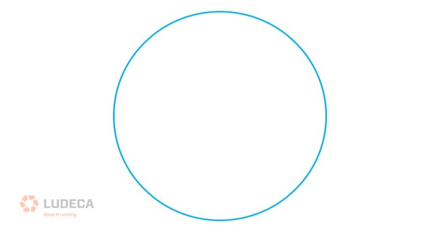
If we have the defect of an unacceptably high unbalance, this rotor will intensify its propensity to follow this circular orbit, and the amplitudes will also become more comparable to one another at the H and V orientations as long as no resonance manifests itself.
On the other hand, if we get a zero or near zero-degree phase shift between the two points, the most common culprit will be misalignment. The first time I was confronted with such data, my initial reaction was, “how can the heavy spot be at the horizontal sensor and the vertical sensor simultaneously? To answer this question, the orbit visualization helps greatly. With the orbit shape below, one can see that the highest amplitude on both sensors will be reached virtually simultaneously.
Orbit: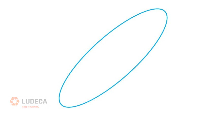
Note: A 180° to near 180° phase difference indicates the same type of elliptical motion. Here the forces of misalignment are constraining the movement of the rotor to ‘jerk’ from one area of freedom to the other and restricting the rotor from following the normal path of unbalance force in a rotor.
Filed under:
Vibration Analysis by Mike Fitch CRL