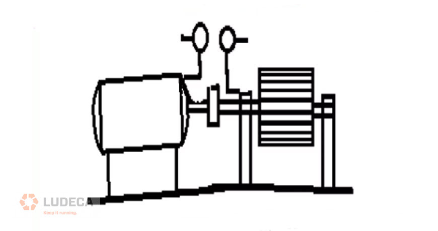
Misalignment: High amplitude peaks will appear at 1×, 2×, and sometimes 3× the running speed. Look for a 180° (± 30°) phase change across the coupling in the axial direction (for angular misalignment) or radial direction (for parallel (offset) misalignment). Bearing misalignment (cocked bearing) will cause a twisting motion in the axial direction. Look for a 180° (± 30°) phase change from the top to the bottom of the bearing housing or from one side to the other.
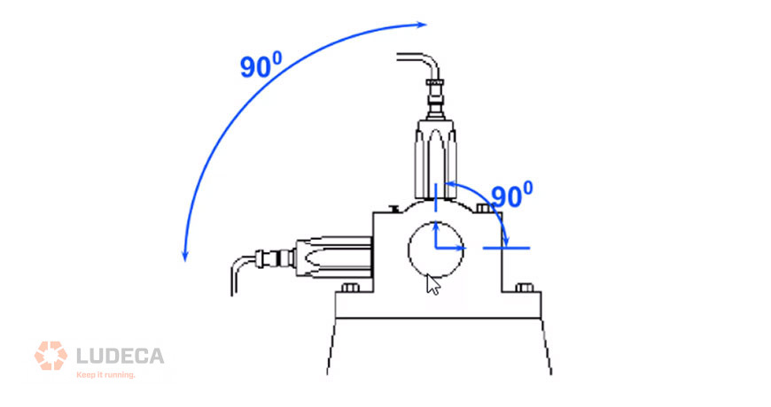
Imbalance: A high amplitude peak will appear at 1× the running speed. Confirm that the phase difference from horizontal to vertical on the bearing is close to 90° (± 40°). The phase difference between left and right horizontal locations should be within 30° of the phase difference between left and right vertical locations. If the phase is unstable, there may be another reason for a large running speed vibration, e.g. looseness or misalignment.
You can investigate the degree of couple imbalance versus force imbalance by looking at the phase difference between the two sides of the machine—if there is little couple imbalance then only a single plane correction may be required to balance the rotor.
Resonance (flexible structures): High amplitude peaks will appear where natural resonance frequencies of the structure coincide with excitation frequencies (e.g. 1×, or other low orders of running speed, blade pass frequency, etc.) Look for a 0° phase change when both sensors are positioned in the same direction between two stationary points. The phase change will be 180° when there is a stationary point between the sensors.
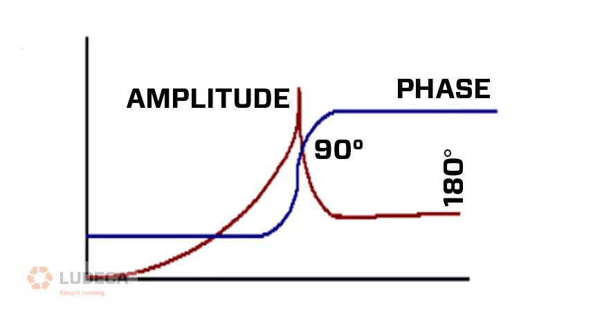
Resonance (variable speed machines): To investigate resonance you can vary the machine speed. A phase shift of 180° will occur as machine speed is increased from below a resonance to above a resonance. A 90° phase shift will be present at the resonant frequency. If a machine is running close to resonance, any small speed variation will cause large phase shifts.
Resonance (at a bearing): Look for a change from the normal 90° phase difference in the horizontal and vertical directions at 1×. When a natural frequency is close to 1× in either direction, that phase angle may well be on the way towards its 90° phase change so the two phases may no longer be 90° apart (assuming that the structure has a different natural frequency in either direction).
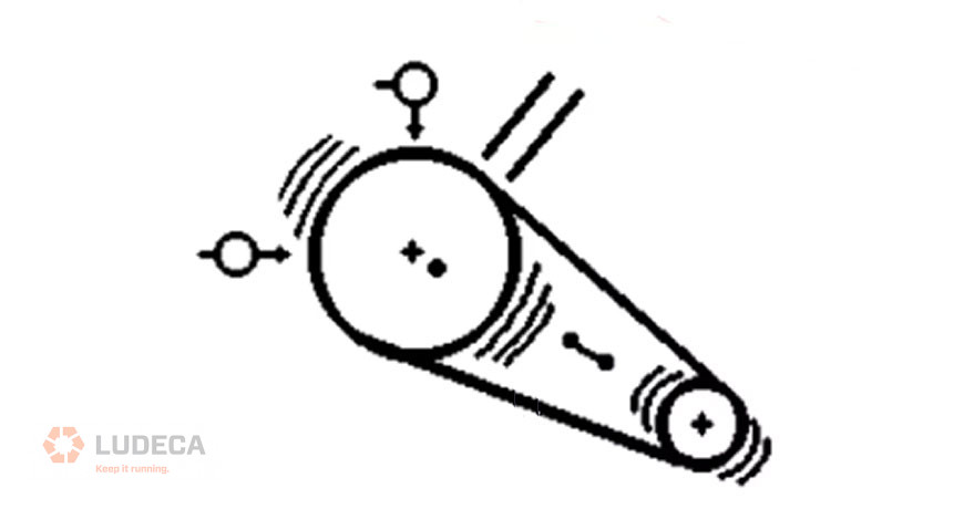
Eccentric belt pulley: A high amplitude peak will appear at 1× the running speed of the pulley. Look for a phase change of either 0° or 180° between the horizontal and vertical readings, which indicates straight line motion instead of the usual 90° difference. This symptom is similar to bearing resonance (described above), however, in this case, the direction of maximum vibration will be in line with the two belts.
Mechanical looseness: High amplitude peaks will show up at many multiples of the running speed, and sometimes even multiples of 0.5× running speed, e.g. 1.5×, 2.5×, etc. Look for fluctuating phase readings at a location from one recording to the next, to the next. Also, compare the phase readings at 30° increments around a bearing housing—the phase will be significantly different at each angle.
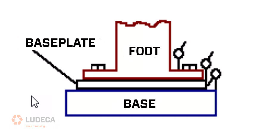
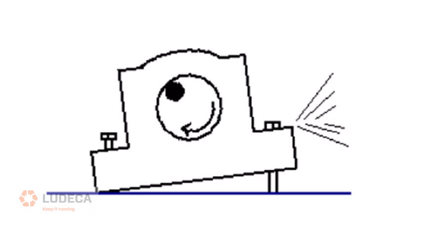
Mechanical foot looseness (soft foot): A high amplitude peak will show up at 1× the running speed. Look for a 90° to 180° phase change between the machine foot and its concrete base. The soft foot may also have a different phase measurement from the other feet.
Learn more about our VIBWORKS vibration analyzer.
Phase Measurement: What is it for? And how you can use it to diagnose failures in 2020.
Filed under:
Vibration Analysis by Dave Leach CRL CMRT CMRP