Machinery Lubrication • September 2022
Imagine buying a new car and not taking it for a test drive first. That might not be so bad, given the built-in protections covering the auto buyer these days. But what about buying industrial equipment? Purchasing a new machine and finding unexpected problems after installation and integration into your manufacturing process is the stuff maintenance and production nightmares are made of.
Of course, you will have a warranty, just like when buying a car. You might even be entitled to a loaner. But none of this is of any real use to you if your problems and production disruptions continue.
In most industries, the process of manufacturing is just slightly less expensive than the price received for the product manufactured; the margin is tight. This being the case, unplanned costs are unwelcome additions to the manufacturing process. Most modern industries have recognized the value of process engineering and are making sure that capital expenditures for industrial machines are spent on the right machines.
To meet that challenge, acceptance testing can be employed, and if properly designed and implemented, the likelihood of unplanned costs incurred after commissioning can be virtually eliminated. Most facilities don’t “design” their acceptance testing, but rather simply apply a standard overall measurement considered to represent a typical machine in “generally” good condition. This is much better than no acceptance testing and means you probably get “generally” good results.
But if you prefer to ensure good results, then you might want to actually design your acceptance testing to do so. Here’s how:
1) One key component of acceptance testing will include gathering vibration data. Understand that an overall vibration signal is a conglomerate of numerous components. Among those components are:
- RF (rotational frequency) or 1× rotational speed, which is the primary indicator of the amount of unbalance present.
- 2× RF, often an indicator of misalignment.
- 3× RF, also often an indicator of misalignment and/or mechanical looseness, or a coupling defect for certain types of couplings.
- Electro-mechanically generated vibration (inherent in electric motors and acceptable at certain levels.)
- ½ RF (and/or other sub-synchronous vibration.)
- Vane or blade passing frequency vibration (inherent in certain equipment and acceptable at certain levels.)
Note that no mention is made of bearing defect-generated vibration. We assume acceptance testing will mostly take place on new or refurbished assets, hence, if there is a bearing defect it will contribute to the overall vibration measurement, but its contribution will be relatively small until the bearing is well on its way to failure. In fact, most early to mid-stage bearing defects will not, by themselves, cause machines to fail the generally used acceptance standards.
Consider that a vibration signal where the RF constitutes ¾ or more of the overall signal would be considered acceptable/ This is the expected healthy percentage. The reason is, in a typically healthy machine, the residual unbalance is the dominant vibration. Unbalance to some level is always expected, and when the residual unbalance is reduced to a level that won’t adversely affect the equipment service lifetime, this is acceptable. Therefore, if the unbalance is limited to a healthy level and that level represents 80-90% or more of the overall vibration, then that machine is highly likely to be a healthy machine.
Now consider that many of the standard overall measurements used for acceptance testing have no way of determining what percentage of the measurement constitutes any certain vibration component.
Therefore, augmenting the standard broadband overalls (also called “unfiltered measurements”) with well-designed narrow band limits (Technical Associates of Charlotte’s ‘Proven Method’ being an example of this) might be a good idea. Adding an RMS acceleration band or two for anti-friction bearing machines is another possibility.
One client we have tested for has enhanced their acceptance criteria by adding a few additional specific frequency component requirements to the standard acceptance overalls. Their added specifications run something like this:
- No individual peaks in the spectra shall exceed 40% of the RF peak when the RF peak is above 0.08 inches/sec.
- No bearing defect frequencies shall be observable in the vibration spectra.
Next, approach acceptance testing like you should approach condition monitoring in any other situation. Test for the applicable failure modes. Is it farfetched to expect a new machine to be free of incipient defects? If your answer is “no”, design your acceptance testing requirements to identify failure modes and exclude their detectable presence in new/rebuilt installations.
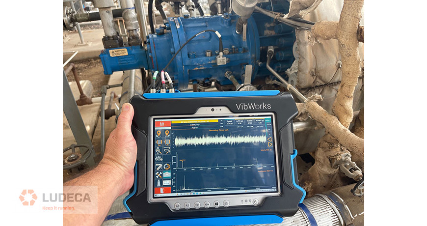
Make sure your acceptance testing includes our VIBWORKS vibration analyzer.
Filed under:
Vibration Analysis by Mike Fitch CRL