Repost from Benchmark PDM Maad Blog

Let us review this case study on a common issue when working on a pump and motor alignment done by Brian Franks, Owner and Field Service Technician of JetTech Mechanical.
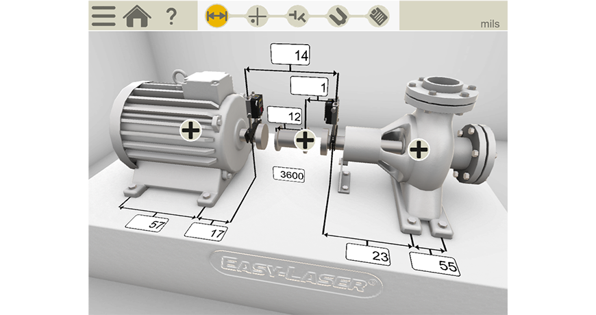
He begins in the normal manner entering the distances of the machine. As you can see this is not a small machine (see Figure 1 below) – there are 57 inches between the motor’s feet and if you add all the measurements together you have 87 inches from the Stationary laser detector unit and the back foot of the movable machine (motor). Notice also that it is a spacer coupling.

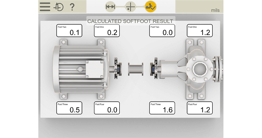
He continues doing the alignment work by taking a soft foot measurement on each of the machines and as you can see, there is very little, so we know it’s a stable base that the machine units are sitting on.

An important note is that they would need the coupling open/loose and the pipe disconnected in order to do this correctly.
The new ANSI standard (ANSI/ASA S2.75-2017/Part 1) allowable soft foot tolerance is two thousandths (0.002 thou or 2.0 mils) of shaft deflection and he is below this, so he is good to go. He documents it for his report.
He now performs the machines’ shaft to shaft alignment.
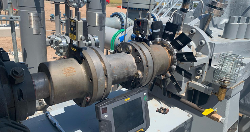
Notice that he’s removed most of the bolts from the coupling in order to allow the coupling to flex. This is a stiff coupling so you don’t want it locking up during the alignment and you also want to make as few moves as possible. So, this is a good practice. This also tells me they know what they are doing which is good.
The tool they are using is an Easy-Laser XT770 which is a dot laser system that can read in the horizontal and vertical plane.
Click here to read the entire case study “A Case Study on Why Pipe Strain Needs To Be Measured”
Filed under:
Alignment, Articles and Case Studies by Diana Pereda
