
When using a laser shaft alignment system, one of the most important things to understand is how the laser adjustment wheels work. These wheels allow you to move the position of laser dot on the detector to place it where you need it to take full advantage of the detector’s range. The laser dot does not necessarily need to be in the center of the detector when you begin your measurement.
Think of it the same way you would use a dial indicator. We don’t always place the plunger exactly in the middle of its travel range as this may limit our measurement in either direction. Depending on the situation, we may intentionally position the plunger farther in or farther out so that we have enough usable travel range to measure the movement we expect.
The same principle applies to the adjustment wheels on a laser alignment system. We use them to strategically position the laser dot where it needs to be to allow us to measure the misalignment. Understanding this concept allows technicians to get the most out of the measurement system and, more importantly, avoid limiting the measurement range of the detector unnecessarily.
The image below illustrates how a dot on the bottom right is ideal if the misalignment moves the laser dot to the left and up:
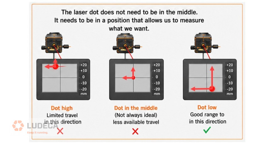
Use the adjustment wheels as a tool to help—not just to center the laser!
As you begin turning the shafts, carefully observe which way the laser dot travels on the detector. Then, next time around, you can deliberately readjust the laser’s position in the opposite direction by as much as possible, in order to maximize the travel range of the beam as you turn the shafts again. This little trick might save the day in allowing you to obtain enough shaft rotation to get good readings, whereas when you start centered you might run out of range too soon and not get reliable readings.
I use a Laser Alignment System, so I am Performing Precision Alignment, Right?
Filed under:
Alignment by Carlos Bienes CRL