
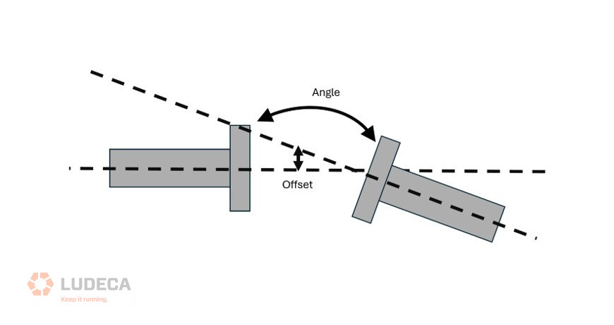
Reliability professionals have often asked us whether laser shaft alignment systems measure using the “rim and face method”. The question is understandable because results are typically reported as offset (radial separation of shaft centerlines at the coupling) and angle (angular misalignment, sometimes expressed as gap difference across the coupling faces). These values are compared to industry tolerance tables such as ANSI/ASA standards to determine if alignment is acceptable. Understanding the evolution of alignment techniques clarifies how today’s laser tools work and why they do not rely on the traditional rim and face approach.
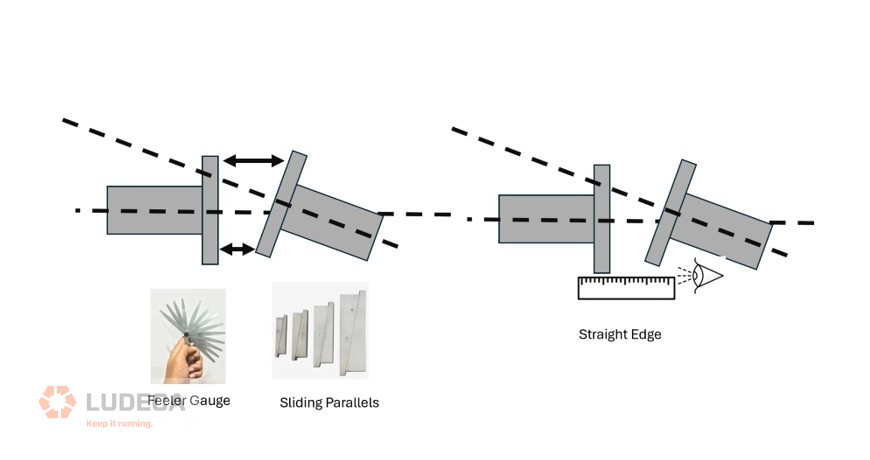
The earliest methods used simple mechanical tools. A straight edge was placed across the coupling rims (top and sides) to check for parallel offset. If no light showed underneath, offset was considered corrected. Feeler gauges measured gaps at multiple points around the coupling face to detect angular misalignment; equal gaps indicated parallel faces. Adjustments were made by shimming or moving machines until both offset and gap fell within acceptable limits. While this gave a basic starting point, it lacked precision and repeatability due to variations in feel, tool placement, and surface irregularities, not to mention that the positioning of the coupling itself was not guaranteed to be exactly with the shaft centerlines of rotation.
As practices advanced, the rim and face methods with dial indicators became popular. One indicator measured rim offset while another on the face captured angular changes as the shafts were rotated together. Rotation physically cancels surface imperfections such as nicks, burrs, or coupling runout. This provided numerical results and better accuracy than straight edges and feeler gauges. However, axial float or end play in the shafts often introduced errors in the face readings, requiring repeated measurements and careful calculation.
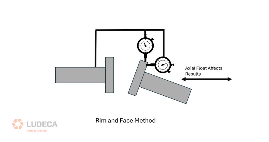
Speaking of calculation, I rarely saw calculations or graph paper being used for dial indicator alignments in my interactions with various facilities. Perhaps this explains why the rim and face method remained popular—it was much easier to conceptually visualize the alignment based on the dial indicator readings alone. Simply taking the Total Indicated Runout (TIR) /2 of the rim readings would give you the shaft offset. Take the gap reading and note the coupling face diameter—that was your angle, for which you could use a multiplier based on that coupling value to figure out the shim corrections. Experienced professionals could and often did literally do that in their heads. Not everyone had that skill, thus computers came into the picture to make that task easier.
A more reliable solution emerged with the double dial indicator (reverse rim) method. Instead of measuring the face directly, two rim readings are taken at opposite sides of the coupling, spaced some distance apart along the axis of the shafts. Using half the total indicated reading (TIR) and the distance between measurement planes to the coupling center, technicians could calculate both offset and angle. This approach largely eliminated errors from axial play.
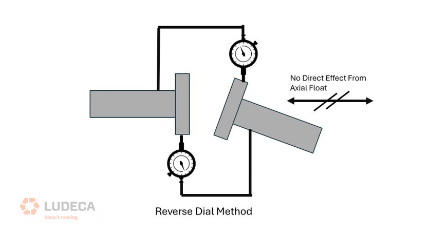
Modern laser alignment systems, such as the Easy-Laser XT770, build directly on this double offset principle. They use laser beams and position-sensitive detectors (PSD)—essentially highly precise, non-contact “dial indicators.” Whether using dual laser/detector setups on both shafts or a single laser with fixed detector positions, the systems capture a minimum of three sets of offset readings at different rotational angles.
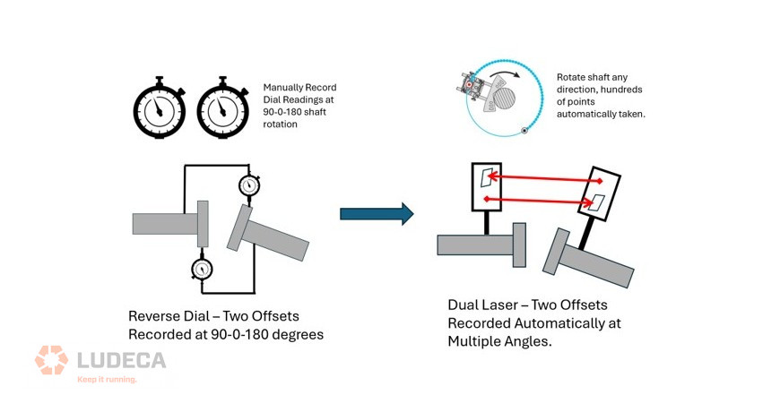
The best, such as Easy-Laser, capture hundreds of sets of readings for accuracy assurance in field conditions. Software then converts these into the familiar offset and angle (or gap) values for tolerance comparison. In addition to higher measurement resolution, key advantages include eliminating mechanical linkages and bar sag errors (typically 10-20 mils or 0.25-0.5 mm if overlooked) while automatically handling calculations.

By appreciating this foundation, reliability teams can better understand how laser tools enhance precision alignment practices, reduce training expense, reduce unplanned downtime, and support long-term asset health—core elements of effective maintenance programs.
Filed under:
Alignment by Daus Studenberg CRL